4. ISTRUZIONI PER L'INSTALLATORE QUALIFICATO
4.1 INSTALLAZIONE DELL'APPARECCHIATURA
•Togliere l’apparecchiatura dall’imballo, assicurarsi dell’integrità
della stessa e in caso di dubbio non utilizzarla e rivolgersi a
personale professionalmente qualificato.
Posizionare l’apparecchiatura sempre sotto una cappa di
aspirazione, dopo essere posta in opera, dovrà essere livellata
agendo sui piedini.
•L'allacciamento dell'apparecchiatura deve essere effettuato
sempre mediante tubazioni rigide in acciaio zincato o rame.
Tutte le tenute sui filetti di giunzione, devono essere garantite da
materiali certificati per l’utilizzo con i gas.
•Se l'apparecchiatura viene installata a parete, a contatto con
materiale infiammabile, occorre interporre tra apparecchiatura e
parete uno strato di materiale isolante resistente al calore,
oppure lasciare uno spazio di 200 mm tra apparecchiatura e
parete.
•L'impianto a gas a monte dell'apparecchiatura, così pure le
caratteristiche dei locali nei quali viene installata
l'apparecchiatura, devono rispondere alle norme in vigore.
•Prima di allacciare l’apparecchiatura si deve verificare la
corrispondenza tra i gas di predisposizione della stessa, e quello
disponibile per l’alimentazione al fine di verificare l’idoneità. Se
non si trova la corrispondenza tra i due si deve procedere come
descritto nel paragrafo “Trasformazione per il funzionamento con
altri gas”
•Applicare sempre un rubinetto di intercettazione fra ogni
apparecchiatura e la tubazione di allacciamento del gas.
•Verificare che l'aerazione dei locali sia sufficiente durante il
funzionamento dell'apparecchiatura, considerando che la
quantità di aria necessaria alla combustione è di 2 m³/h di aria
per ogni kW di potenza installata.
4.2 NORME DI LEGGE, REGOLE TECNICHE E LINEE
GENERALI
•Norme prevenzione infortuni.
•Attenersi alle prescrizioni e alle Norme di riferimento in vigore nel
paese in cui l’apparecchio viene installato
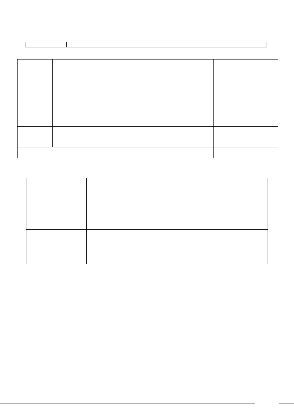
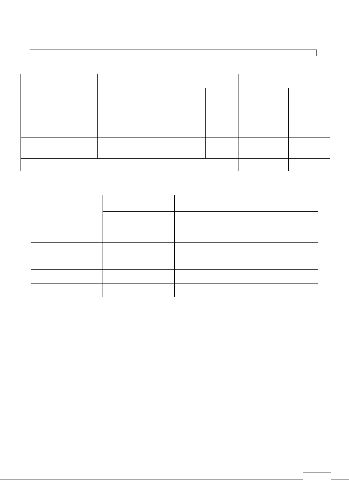
4.3 SCARICO FUMI PER APPARECCHI TIPO "A"
Gli apparecchi devono essere installati in locali adatti per lo scarico dei
prodotti della combustione, che deve avvenire nel rispetto di quanto
prescritto dalle norme di installazione. Le nostre apparecchiature sono
considerate, (V. Tabelle Dati Tecnici), come apparecchi a gas di tipo
"A" non previste per essere collegate ad un condotto naturale di scarico
dei prodotti della combustione.
Tali apparecchi devono scaricare in apposite cappe, o dispositivi
similari, collegate ad un camino di sicura efficienza oppure direttamente
all'esterno.
In mancanza è ammesso l'impiego di un aspiratore di aria collegato
direttamente all'esterno, di portata non minore di quanto richiesto, V.
tabella 1, maggiorato del ricambio d'aria necessaria per il benessere
degli operatori.
4.4 CONTROLLO PERDITE GAS
Ad installazione avvenuta, è necessario controllare che non ci siano
perdite di gas sulle giunzioni delle tubazioni, mediante soluzione di
acqua saponata; eventuali perdite verranno segnalate da bolle di
schiuma. Non adoperare mai fiamme per controllare eventuali perdite.
Con l'apparecchiatura pronta per l'uso, controllare che non ci siano
perdite di gas, verificando sul contatore, se inserito (per un periodo di
30 minuti), che non ci sia passaggio e consumo di gas.
5. MANUTENZIONE
La manutenzione è ridotta al minimo, per effetto di una corretta
costruzione delle apparecchiature. Tuttavia, si consiglia di far
controllare gli impianti da personale qualificato, almeno due volte l'anno.
N.B.: il costruttore declina ogni responsabilità per danni diretti o
indiretti causati da errata installazione, cattiva
manutenzione, manomissioni, usi impropri e dal mancato
rispetto delle norme antinfortunistiche di prevenzione
incendi e di sicurezza per gli impianti a gas.
5.1 TRASFORMAZIONE PER FUNZIONAMENTO CON ALTRI
GAS – FRG
L'apparecchiatura viene collaudata e predisposta per funzionamento a
gas secondo quanto indicato nella tabella caratteristiche posta in
prossimità dell'entrata gas sull'apparecchiatura.
Per funzionamento con altri gas procedere come di seguito indicato:
•La trasformazione deve essere effettuata da personale
qualificato
•La dotazione degli ugelli per la conversione ad un altro tipo di
gas, diverso da quello che era stata predisposta
l’apparecchiatura, normalmente è contenuta in un sacchetto di
nylon con relative etichette supplementari riportanti tutte le
tipologie dei gas.
Se la dotazione non fa parte del corredo, si deve richiederla al
concessionario/importatore accertandosi prima che
l’apparecchiatura possa funzionare con altri tipi di gas.
Una volta terminata la trasformazione e le dovute regolazioni,
bisogna applicare nello spazio apposito della targhetta
caratteristiche, la etichetta relativa al gas corrispondente,
ritagliando quella interessata.
•Sostituzione ugello bruciatore (fig. 1):
togliere il cruscotto (20) e sostituire gli ugelli (30) secondo il tipo
di gas (vedi tabella DATI TECNICI).
•Sostituzione ugello bruciatore pilota:
togliere il cruscotto (20), svitare il dado del bruciatore pilota e
sostituire l'ugello (19) secondo il tipo di gas (vedi tabella DATI
TECNICI).
•Regolazione dei bruciatori, verifica pressioni di alimentazione e
funzionamento:
effettuata la sostituzione degli ugelli, verificare che le pressioni
del gas, sia in entrata che in uscita della valvola, siano quelle
riportate sulla tabella DATI TECNICI. Per fare questo, togliere le
viti situate sulla presa di pressione (11) della valvola (1), inserire
un tubo di gomma collegato ad un manometro e controllare la
pressione. Se la pressione in entrata, dovesse risultare diversa
da quella prescritta, ricercare la causa e provvedere a renderla
secondo quanto prescritto.
•Regolazione bruciatore pilota:
il bruciatore non necessita di alcuna regolazione.
•Regolazione del minimo – bruciatore:
la valvola ha funzionamento acceso/spento, quindi non necessita
di regolazione.
5.2 SOSTITUZIONE PARTI DI RICAMBIO
•Valvola termostatica (6):
togliere il cruscotto (1), svitare i raccordi di collegamento entrata
(9) ed uscita (10). Svitare il raccordo (11) tubetto pilota e la
termocoppia (12). Svitare le viti (13) di fissaggio della valvola al
supporto. Sfilare il bulbo del termostato (31) dalla vasca (14)
dopo averla svuotata dell'olio e aver svitato il premistoppa (15).
Sostituire la valvola e rimontare il tutto controllando la tenuta
dell'olio sul premistoppa (15) con l'olio caldo in vasca.
ATTENZIONE: il bulbo del termostato della valvola (31) deve
essere posizionato verso l'interno della vasca (fig. 1)
•Termostato di sicurezza (8):
svuotare la vasca dall'olio, svitare il premistoppa (16), estrarre il
bulbo del termostato (8), sostituire il termostato. Rimontare il
tutto controllando la tenuta dell'olio sul premistoppa (16) con
l'olio caldo in vasca.
ATTENZIONE: il bulbo del termostato (32) deve essere
posizionato verso la parte esterna della vasca.
•Termocoppia (12):
svitare la termocoppia (12) dalla valvola (6) e dal pilota (17),
quindi sostituirla.
•Candela di accensione (18):
svitare il dado di fissaggio candela (19) al pilota e sostituire la
candela.
•Accenditore piezoelettrico (20):
sfilare il cavo di collegamento candela, svitare il dado di
fissaggio del piezoelettrico al cruscotto e sostituirlo.
•Sostituzione bruciatore (27):
svitare le due viti di fissaggio del bruciatore alla vasca, svitare il
dado (28) di fissaggio del porta - ugello (29). Sostituire il
bruciatore e rimontare il tutto.
N.B.: Dopo ogni sostituzione o riparazione, controllare il corretto
funzionamento degli organi sostituiti e provvedere alla messa a
punto degli stessi.
Controllare le tenute sui raccordi gas con acqua saponata, non
usare mai fiamme libere.
6. ISTRUZIONI PER L’UTENTE
6.1 ACCENSIONE DEI BRUCIATORI FRIGGITRICE
Accensione fiamma pilota:
Accertarsi che la manopola della valvola di sicurezza termostatica sia
sulla posizione CHIUSO (simbolo ). Premere a fondo il pulsante
e mantenendolo premuto, spingere contemporaneamente il pulsante