Matrox NRG User manual

User Guide
20314-301-0100
2021.06.30
Matrox
®
NRG
Redundant Power Supply Unit
eng_Matrox NRG User Guide.book Page 1 Wednesday, June 30, 2021 4:31 PM

2
Contents
Matrox safety information ...................................................................................... 4
Installation and operation .......................................................................................................................4
Power ........................................................................................................................................................4
Repair .......................................................................................................................................................5
Overview ................................................................................................................. 6
Hardware supplied ...................................................................................................................................6
Hardware required (sold separately) ...................................................................................................... 7
Optional hardware (sold separately) ......................................................................................................7
More information ....................................................................................................................................7
Connecting your devices and powering up Matrox NRG ..................................... 8
Matrox NRG unit rear connections ........................................................................................................8
About the Matrox NRG rackmount .........................................................................................9
Connection overview ...............................................................................................................................9
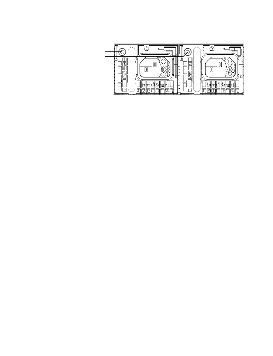
Replacing power supply units .............................................................................. 11
Connecting Matrox NRG to your network ........................................................... 13
Connecting to a DHCP-enabled network ............................................................................................13
Connecting to a network using a static IP ............................................................................................13
Updating Matrox NRG .......................................................................................... 16
Connecting to the Matrox NRG user interface .................................................... 18
Validating your Matrox NRG setup ...................................................................... 19
Description of LEDs ..............................................................................................................................19
Front of device .........................................................................................................................19
Back of device ..........................................................................................................................19
Network connector .................................................................................................................19
Product information .............................................................................................. 20
Power input ............................................................................................................................................20
Power outputs ........................................................................................................................................ 20
I/O control .............................................................................................................................................20
General ...................................................................................................................................................21
Environmental .......................................................................................................................................21
EMC / Safety ..........................................................................................................................................22
eng_Matrox NRG User Guide.book Page 2 Wednesday, June 30, 2021 4:31 PM

3
GPIO pinouts .........................................................................................................................................22
Pinout mapping ......................................................................................................................23
Customer support ................................................................................................. 24
Matrox web ............................................................................................................................................ 24
Technical support ..................................................................................................................................24
Information we need ..............................................................................................................24
View your warranty information ..........................................................................................................24
View the third party software notices ...................................................................................................24
Register your Matrox product ............................................................................................................... 24
eng_Matrox NRG User Guide.book Page 3 Wednesday, June 30, 2021 4:31 PM

Matrox NRG User Guide 4
Matrox safety information
To ensure safe and reliable operation of your Matrox product, to avoid personal injury, and to prevent
damage to your computer or Matrox hardware, read the following guidelines.
Installation and operation
Read and retain all instructions. Only use your Matrox product according to the
instructions, operating ranges, and guidelines provided in the Matrox user guide and
other related Matrox documentation. Failure to follow these instructions could result in
damage to your product or injury to the user or installer.
Don’t expose your Matrox product to rain, water, condensation, or moisture.
Static electricity can severely damage electronic parts. Before touching any electronic
parts, drain static electricity from your body (for example, by touching the metal frame
of your computer).
Don’t stack devices or place devices so close together that they’re subject to recirculated
or preheated air.
Don’t operate your system or Matrox product near a heat source or restrict airflow to
your system, and make sure the ambient temperature doesn’t exceed the maximum
recommended temperatures. Don’t block ventilation holes on your unit or system.
This product is designed for use in a “Pollution Degree 2” environment.
Power
Only use replaceable power supply modules originally supplied with the product or use
a replacement that’s supplied by Matrox. Don’t use modules that appear to be defective
or damaged.
AC-powered products must be connected to a grounded outlet installed by a licensed
electrician. Don’t defeat the safety purpose of the polarized or grounding-type plug of
the NRG unit. A polarized plug has two blades with one wider than the other. A
grounding-type plug has two blades and a third grounding prong. The wide blade or the
third prong are provided for your safety. If the provided plug doesn’t fit into your outlet,
consult a licensed electrician to replace the obsolete outlet.
Make sure that nothing rests on the power cables and that the cables aren’t located where
they can be stepped on, pinched, or tripped over.
Don’t use damaged power cables.
eng_Matrox NRG User Guide.book Page 4 Wednesday, June 30, 2021 4:31 PM

Matrox NRG User Guide 5
Unplug your system or device during lightning storms or if unused for long periods of
time.
Before removing or replacing a power module, make sure to disconnect its AC power
cable.
Repair
Don’t attempt to open or repair your Matrox product.
Don’t attempt to open or repair a replaceable power supply module.
If there’s a fault with your Matrox product, review your Matrox warranty for more
information.
eng_Matrox NRG User Guide.book Page 5 Wednesday, June 30, 2021 4:31 PM

Matrox NRG User Guide 6
Overview
Thank you for purchasing a Matrox NRG product. Matrox NRG is an external, rack-mountable, dual
redundant Power Supply Unit (PSU) which can be used to power virtually any 12 volt appliance
currently manufactured by Matrox Video, including the Maevex 6100 Series, Extio 3 Series,
QuadHead2Go Series, and Monarch EDGE Series.
Up to five appliances can be powered by a single NRG unit. The NRG units come equipped with two
300 watt power supply modules, either of which can be replaced without interrupting the power
output to the connected appliances. The modules include automatic load balancing which ensures
even usage of both power supplies and extends the life of each.
The single density solution ships with a single NRG unit installed on a 1U rack-mountable tray with
space for any ½ wide appliance to be installed next to it. The dual density solution includes two NRG
units installed on a single 1U tray.
Matrox NRG key features:
2 x field-replaceable redundant power supply modules (300 watts each). You can
individually replace either power supply module without unplugging the other module,
ensuring a continuous 12 volt output to your connected devices.
High density device capable of powering five units from a single PSU.
One (1) RU in height. One half (½) RU width.
Comes pre-installed on a rack tray with the other half of the tray available for your
Matrox appliance.
GPIO connection to signal a possible error condition.
10/100 BASET Network connection to provide monitoring and control via management
software (Matrox or custom).
Remote control via IP of each power output.
Recessed physical rocker switch (on-off) on the device.
On device LEDs to display status.
Hardware supplied
Depending on your NRG device, the following hardware is supplied:
One (1) or two (2) six-foot long power cables (DIN 4-pin male with lock).
Rack mountable NRG RPSU.
eng_Matrox NRG User Guide.book Page 6 Wednesday, June 30, 2021 4:31 PM

Matrox NRG User Guide 7
Mounting screws.
Hardware required (sold separately)
Depending on your device and setup, you may need the following hardware:
IEC power cables.
*
CAT5e, CAT6, or CAT7 cable.
GPIO Female DB-9 low profile connector.
Optional hardware (sold separately)
You may also need any of the following hardware (available for purchase from Matrox):
Spare and/or replacement power supply module(s).
†
Spare and/or replacement power output cables.
‡
More information
Your Matrox NRG User Guide provides information on installing and connecting your Matrox
hardware, updating your firmware package, and using the NRG configuration software.
Be sure to check for any last-minute release notes included with your product. Also, check the Matrox
website (www.matrox.com/video) for the latest Matrox software, technical support, and product
information.
* All NRG-compatible Matrox appliances include IEC power cables that can also be used with Matrox NRG. For North America
only, use a cord set (provided by Matrox) bearing P/N FCABLE050 with the NRG. If needed, you can purchase additional cables
from Matrox.
† You can purchase additional power supply modules from Matrox (part number NRG-5-PM)
‡ You can purchase a set of four 6-foot cables (double-ended DIN 4-pin male with lock) from Matrox under part number CAB-
DIN4-6FT-4.
eng_Matrox NRG User Guide.book Page 7 Wednesday, June 30, 2021 4:31 PM

Matrox NRG User Guide 8
Connecting your devices and powering
up Matrox NRG
This section describes how to connect and power up your Matrox NRG device.
Matrox NRG unit rear connections
Connector Description
DIN 4-Pin 1 x 12V / 3A output, 4 x 12V / 5A output. Make sure any connected Matrox
device supports the connector’s power rating.
LAN Connect a network cable to this connector.
GPIO A low profile DB-9 connector which provides GPIO (General Purpose I/O)
that can indicate if a power module has failed, as well as provide a reset
switch to reconfigure the device.
Pin 1 provides fault status of the power modules. It is a latched tally output
(passive) which can accept a 0.75A (maximum) current at a maximum
voltage of 20V.
Pin 9 is to be used to reset the network settings via a simple grounding
operation. Pin 5 is a ground connection. There is a reset pin hole at the top
of the NRG unit which executes the same reset operation as the grounding
of Pin 9.
Pins 2, 3, 4, 6, and 8 are not assigned.
For more information, see “GPIO pinouts” on page 22.
100-240V input 100-240V input for first power supply module.
100-240V input 100-240V input for second power supply module.
DIN 4-Pin
LAN GPIO 100-240V input 100-240V input
eng_Matrox NRG User Guide.book Page 8 Wednesday, June 30, 2021 4:31 PM

Matrox NRG User Guide 9
About the Matrox NRG rackmount
Matrox NRG comes pre-installed on a standard 1RU rackmount shelf. If you have a single
unit NRG model, there is space on the shelf for another Matrox appliance next to it.
For more information on how to install other devices on the shelf, go to our website at:
https://www.matrox.com/en/video/products/rackmount-kit-instructions.
Connection overview
This section describes how to connect your devices and power on Matrox NRG.
1
Before you connect any devices to your Matrox NRG, make sure that the power switch
on the front panel is in the OFF position. This ensures that no power is coming from the
DIN 4-Pin 12V d.c. outputs.
2
Connect your Matrox devices to the DIN 4-Pin 12V d.c. outputs on your Matrox NRG.
Make sure that you insert the connectors in the correct orientation (i.e. locking latch is
in the correct position). Do not use excessive force to insert the connectors.
Output 1 supports 12V d.c. 3A devices only. Devices requiring more than 3A may not
boot or function as intended if they are on output 1. Verify the voltage and/or current
requirements specified on the Matrox device(s) you intend to use with Matrox NRG.
Matrox NRG-5-1DB (single unit model)
Power to the 12V d.c.
outputs is OFF
12V d.c. 3A
devices only
12V d.c. 5A devices
eng_Matrox NRG User Guide.book Page 9 Wednesday, June 30, 2021 4:31 PM

Matrox NRG User Guide 10
3
Make sure that your Matrox NRG’s two field-replaceable power supply modules are fully
inserted (they may have shifted or loosened during transport), then connect AC power
to one or both power supply modules.
As the Matrox NRG does not come with an IEC 60320 C13 power cable, you can use the
cable included with the Matrox appliance you intend to use with Matrox NRG, or any
locally sourced IEC 60320 C13 cable that meets local regulatory requirements.
4
Turn ON the Matrox NRG’s front panel power switch to power on the 12V d.c. outputs.
The LED on the front will turn GREEN if both power modules are active, or blink
GREEN if one module is not functioning.
When the LED is green, your Matrox NRG is ready to provide power redundancy to Matrox
appliance(s).
LEDs are green
when power
supply modules
are active
eng_Matrox NRG User Guide.book Page 10 Wednesday, June 30, 2021 4:31 PM

Matrox NRG User Guide 11
Replacing power supply units
Matrox NRG has fully redundant power supplies. In the event one of the power supply modules fails,
the output load will be completely supported by the second power module. The failed power supply
module can then be replaced without interrupting the power output to connected devices. Although
the power supply modules can be replaced at any time, NRG includes a stiffener bar that must be
physically removed before you can remove either module.
1
Disconnect the AC power cord from the power supply module you want to replace.
2
The Matrox NRG rack has a stiffener bar that partially blocks the power supply modules.
You will need to unscrew the stiffener bar from the rack and remove it to access the
modules.
Stiffener bar (attached)
Stiffener bar (removed)
eng_Matrox NRG User Guide.book Page 11 Wednesday, June 30, 2021 4:31 PM

Matrox NRG User Guide 12
3
Slide the locking lever to unlock the power supply module from the Matrox NRG unit.
4
Pull on the handle to remove the module from the Matrox NRG unit.
5
Insert the new module until the locking lever clicks into place, then re-attach the stiffener
bar.
6
Reconnect the AC power cord to the new module.
The power supply module has been replaced.
Locking levers
Pull handles to remove
eng_Matrox NRG User Guide.book Page 12 Wednesday, June 30, 2021 4:31 PM

Matrox NRG User Guide 13
Connecting Matrox NRG to your network
Matrox NRG is fully functional as a power redundancy device without a network connection, but
network connectivity provides additional benefits such as remote monitoring and reboot capability.
Connecting to a DHCP-enabled network
Matrox NRG is set to a DHCP protocol by default, so a DHCP-enabled network will assign an IP
address to the NRG when it is connected to your network. You’ll need this IP address to connect to
the NRG through a web browser.
1
Connect your Matrox NRG to your network via the LAN connector.
2
From the Matrox website (www.matrox.com/en/video/apps/drivers/home), download
the zip file
NRGUtils_<release number>.zip
, and extract the contents to a folder on your
computer.
3
From the extracted folder, run
NRGupdater.exe.
4
Click
Find
to find your NRG unit on the network (it must be on the same subnet). You
can also use the MAC address printed on the Matrox NRG device itself to find it in your
router manifest.
5
Take note of your NRG unit’s IP address and update the firmware if needed.
If you have the
Matrox NRG-5-2DB
model (i.e. two NRG units on the tray), each unit
has its own dedicated IP address. When you connect to one of the units, you will see an
“A” or “B” as a suffix to the device name. This suffix corresponds to the NRG unit’s place
on the tray which is also marked with A or B.
6
From a web browser (Google Chrome is recommended) go to the IP address of your
Matrox NRG.
7
If this is your first time logging in to Matrox NRG, you will be asked to set your password.
Your Matrox NRG is connected to the network for remote monitoring and other functions.
Connecting to a network using a static IP
If you want to set your Matrox NRG to a static IP address, you can do so with the
NrgIpSetup
application. Setting Matrox NRG to a static IP will reboot your Matrox NRG device. A reboot can take
up to 30 seconds and will result in a power cycle for any connected devices.
1
Connect your Matrox NRG to your network via the LAN connector.
eng_Matrox NRG User Guide.book Page 13 Wednesday, June 30, 2021 4:31 PM

Matrox NRG User Guide 14
2
From the Matrox website (www.matrox.com/en/video/apps/drivers/home), download
the zip file
NRGUtils_<release number>.zip
, and extract the contents to a folder on your
computer.
3
From the extracted folder, run
NRGipsetup.exe.
4
The application opens and automatically detects any Matrox NRG device(s) on your
network (it must be on the same subnet).
Since all Matrox NRG devices are set to DHCP by default, the fields will all have values
of zero (0) initially.
5
Click on the Matrox NRG device you want to configure.
eng_Matrox NRG User Guide.book Page 14 Wednesday, June 30, 2021 4:31 PM

Matrox NRG User Guide 15
6
Enter the static
IP
you want for your Matrox NRG, as well as the
Network Mask
,
Gateway
, and
DNS
. For more information on these fields, contact your network
administrator.
7
Click
Set
to apply the new network settings and reboot the Matrox NRG device. This will
result in a power cycle of all connected devices.
8
(Optional) Click
Launch Webpage
to open your default browser and go to the Matrox
NRG user interface.
Your Matrox NRG device is set to the specified static IP address.
eng_Matrox NRG User Guide.book Page 15 Wednesday, June 30, 2021 4:31 PM

Matrox NRG User Guide 16
Updating Matrox NRG
You can remotely update the Matrox NRG units on your network by using the Matrox NRG updater
application
NRGupdater.exe
. The updater application is in the zip file you download from the Matrox
website and extract to your computer.
1
Make sure your Matrox NRG units are connected to the network as described in
“Connecting Matrox NRG to your network” on page 13.
2
From the Matrox website (www.matrox.com/en/video/apps/drivers/home), download
the zip file
NRGUtils_<release number>.zip
, and extract the contents to a folder on your
computer.
3
From the extracted folder, run
NRGupdater.exe.
The updater application opens with the IP address field displaying all zeros (0).
4
If you know your Matrox NRG unit’s IP address, type it in the
IP address
field, then
continue to step 5. If you do not know your Matrox NRG unit’s IP address, click
Find
to
search for devices on the same subnet, select the unit you want to update, then click
OK
.
5
Click
Browse
, go to the extracted folder that you created in step 2, then select the update
file (e.g.
NRG_1.0.123_APP.s19
).
6
Select or clear
Reboot when complete
.
eng_Matrox NRG User Guide.book Page 16 Wednesday, June 30, 2021 4:31 PM

Matrox NRG User Guide 17
If selected, the Matrox NRG will automatically reboot when the update is complete,
causing all connected devices to perform a power cycle.
7
Click
Update
.
8
When done, click
Close
.
Your Matrox NRG unit has been updated.
eng_Matrox NRG User Guide.book Page 17 Wednesday, June 30, 2021 4:31 PM

Matrox NRG User Guide 18
Connecting to the Matrox NRG user
interface
To control Matrox NRG, you connect to it via a web-based user interface. You must know the unit’s
IP address to connect.
If you have the Matrox NRG-5-2DB model (i.e. two NRG units on the tray), each unit has its own
dedicated IP address. When you connect to one of the units, you will see an “A” or “B” as a suffix to
the device name. This suffix corresponds to the NRG unit’s place on the tray which is also marked
with A or B.
1
Connect Matrox NRG to your network as described in “Connecting Matrox NRG to your
network” on page 13.
2
Open a web browser (Google Chrome is recommended) and go to the IP address of your
Matrox NRG unit. If you see a warning that the website is not secure, you can disregard
it and proceed.
If you don’t know your NRG unit’s IP address, you can use the Matrox NRG updater
application to find it (see “Connecting Matrox NRG to your network” on page 13).
3
Log in to Matrox NRG with your password. If this is your first time logging in, you will
be prompted to set your password.
The Matrox NRG page opens.
4
For more information on how to use the Matrox NRG user interface, click the
Help
link.
Yo u a r e r e a d y t o u s e M a t r o x N R G .
eng_Matrox NRG User Guide.book Page 18 Wednesday, June 30, 2021 4:31 PM

Matrox NRG User Guide 19
Validating your Matrox NRG setup
After connecting your NRG device, we recommend you validate your connection setup and network
discovery before you continue.
Description of LEDs
The LEDs on your device provides information to help you troubleshoot. The following describes the
LED on your NRG device.
Front of device
Back of device
Network connector
The network connectors on your product use indicator lights (LEDs) to
provide information on the network activity and presence. The following
describes the different network connector LEDs.
LED color What it means
No LED (black) Device isn’t powered.
Green (solid) Both power supplies are functioning normally.
Green (slow blink) A power supply is not functioning.
LED color What it means
12V connectors: No LED (black) Output is disabled.
12V connectors: Green (solid) Output is enabled and functioning normally.
12V connectors: Red (solid) Output is malfunctioning.
LED color Network activity Network presence
No LED (black) No network activity detected
(network cable unplugged).
Transmitting at 10/100
BASE-T.
Green (flashing) Network activity detected. —
Amber (solid) — Transmitting at 100 Mbps.
Speed Network
activity
eng_Matrox NRG User Guide.book Page 19 Wednesday, June 30, 2021 4:31 PM

Matrox NRG User Guide 20
Product information
Power input
Power outputs
I/O control
Input voltage 100 - 240V a.c.
Input frequency range 47 - 63 Hz
Input current 5 - 2.5A
Number of output channels 5
Output connector type DIN 4-pin female
Output voltage 12V d.c.
Current per channel Output 1: 3A
Outputs 2 to 5: 5A
Output power per channel Output 1: 36W
Outputs 2 to 5: 60W
Ripple and noise 12V d.c.= 120mv (P-P) (Power-Supply data)
Overcurrent protection per
channel
Output 1: 3.2A
Outputs 2 to 5: 5.2A
Mechanical control Power-on switch
External LEDs Power
1 LED per PSU module
Ethernet
5 power status LEDs*
Communication protocol Ethernet
Communication speeds 10/100 Mbps
Communication security SSH, SSL, HTTPS, certificate support
Communication (other) DHCP, Static IP, password protection
eng_Matrox NRG User Guide.book Page 20 Wednesday, June 30, 2021 4:31 PM
Other manuals for NRG
1
Table of contents
Other Matrox Power Supply manuals
Popular Power Supply manuals by other brands

Sonnen
Sonnen sonnenBatterie eco 7.0 Series Operation and installation instructions

Huapu
Huapu HP-302D-II operation instruction

ADTRAN
ADTRAN NetVanta 1131 RPS/EPS Specifications

TDK-Lambda
TDK-Lambda GXE600 Series instruction manual

Delta Tau
Delta Tau Accessory E1 user manual

Altronix
Altronix TROVE T1KE34D installation guide

Keysight
Keysight EDU36311A Service guide

Phoenix Contact
Phoenix Contact TRIO-PS-2G/1AC/24DC/10/B+D datasheet

JETFON
JETFON JF 20 instruction manual

Kikusui
Kikusui PLZ164W user manual

Rockwell Automation
Rockwell Automation A-B QUALITY 1606-XLS120EA instruction manual

FONESTAR
FONESTAR ZSA-200PS instruction manual