MATSUI 2109 NS
Recommended Safety Parts
Item Part No. Description
R407 R002T21R8J RC 1.8 OHM 1/2W
R428 R5X2CD472J R, CEMENT 4.7K OHM 5W
R429 R6558A010J R, FUSE 1 OHM 2W
R501 R002T2155J RC 1.5M OHM 1/2W
R503 R5 2CE5R6J R, CEMENT 5.6 OHM 7W
R803 R3X18A123J R, METAL OXIDE 12K OHM 2W
R805 R3X18A123J R, METAL OXIDE 12K OHM 2W
R807 R3X18A123J R, METAL OXIDE 12K OHM 2W
C403 E02LT4471M CE 470 UF 35V
C414 E5EZT4101M CE 100 UF 35V
C418 E5EZT3102M CE 1000 UF 25V
C419 C0JTB05Q2K CC 470 PF 500V
C420 C0JTB0513K CC 0.001 UF 500V B
C443 P4N2F9562H CMPP 0.0056UF 1.6KV DKR
C446 E5EZTB010M CE 1 UF 160V
C448 E5EZFC220M CE 22 UF 200V
C501 P2122B224M CMP 0.22 UF 250V ECQUL
C511 E02LT5010M CE 1 UF 50V
C518 E50HU50R1M CE 0.1 UF 50V
C519 E5EZF3222M CE 2200 UF 25V
C521 E53VFB221M CE 220 UF 160V
C526 P2122B224M CMP 0.22 UF 250V ECQUL
D405 D2WTAU02A0 DIODE, SILICON AU02A-EIC
D410 D2WTAU02A0 DIODE, SILICON AU02A-EIC
D501 D2WTRM11C0 DIODE, SILICON RM11C-EIC
D502 D2WTRM11C0 DIODE, SILICON RM11C-EIC
D503 D2WTRM11C0 DIODE, SILICON RM11C-EIC
D504 D2WTRM11C0 DIODE, SILICON RM11C-EIC
D505 D28T21DQN9 DIODE, SCHOTTK 21DQ09N-TA2B1
D510 D2BTRU2AM0 DIODE, SILICON RU2AM V1
D513 D28TQS04N0 DIODE, SCHOTTK 11EQS04N-TA1B2
D517 D2LTPG06J0 DIODE, SILICON RMPG06J-G3
IC401 I01SD5539N IC AN5539N
IC506 0002500560 PHOTO COUPLER TLP621(D4-GR-LF2) or
0002E00610 PHOTO COUPLER TLV-817M-V (2109R only)
Q401 TDUU024990 TRANSISTOR, SILICON 2SD2499(LBOEC1)
Q402 TC3Q026210 TRANSISTOR, SILICON 2SC2621(D,E)-RAC
Q801 TC3F037890 TRANSISTOR, SILICON 2SC3789(D,E)-RA
Q802 TC3F037890 TRANSISTOR, SILICON 2SC3789(D,E)-RA
Q803 TC3F037890 TRANSISTOR, SILICON 2SC3789(D,E)-RA
L501 029T000094 COIL, LINE FILTER 0R7A223F24
L503 028H200015 COIL, DEGAUSS 8H200015
T501 0481290284 TRANSFORMER, SWITCHING 8129028
SW501 0530205002 SWITCH SDDFC30400
CD501 1206635821 CORD, AC 1206635821
F501 0808T04002 FUSE 218004
FB401 043221015F TRANSFORMER, FL BACK 3221015
R 501 0560Q20114 RELA SDT-S-112LMR
TU001 0144W07023 TUNER, UHF NJH3023M218
V801 098A210405 CRT A51EER131*76
(2109T nly)
R806 R002T4272J RC 2.7K OHM 1/4W
C419 C0HTB05Q2K CC 470 PF 500V
C518 CS0RB04Q3K CC 0.0047 UF 50V
IC506 0002500560 PHOTO COUPLER TLP621(D4-GR-LF2 or
0002E00610 PHOTO COUPLER LTV-817M-V
Memory IC Replacement
(2109 NS nly)
(2109 R & 2109 T)
For notes please see matrix.
Electrical Adjustments
1. BEF RE MAKING ELECTRICAL ADJUST-
MENTS
Read and perform these adjustments when
repairing the circuits or replacing electrical parts
or PCB assemblies.
CAUTI N
• Use an isolation transformer when performing
any service on this chassis.
• Before removing the anode cap, discharge
electricity because it contains high voltage.
• When removing a PCB or related component,
after unfastening or changing a wire, be sure
to put the wire back in its original position.
Inferior silicon grease can damage IC’s and
transistors.
• When replacing IC’s and transistors, use only
specified silicon grease ( G6260M). Remove
all old silicon before applying new silicon.
1. Synchro Scope
2. Digital Voltmeter
Prepare the following measurement tools for
electrical adjustments.
n-Screen Display Adjustment
1. In the condition of NO indication on the
screen. Press the VOL. DOWN button on the
set and the Channel button (9) on the remote
control to appear the adjustment mode on the
screen as shown in Fig. 1-1.
2. Use the Channel UP/DOWN button or
Channel button (0-9) on the remote control to
select the options shown in Fig. 1-2.
3. Press the MENU button on the remote control
to end the adjustments.
2. BASIC ADJUSTMENTS
2-1: AGC V LTAGE
1. Receive an 80dB monoscope pattern.
2. Connect the digital voltmeter between the pin
5 of CP101 the pin 1 (GND) of CP101.
3. Activate the adjustment mode display of Fig.
1-1 and press the channel button (02) on the
remote control to select “RF AGC”.
4. Press the VOL. UP/DOWN button on the
remote control until the digital voltmeter is
2.40 ± 0.05V.
2-2: CUT FF
1. Place the set with Aging Test for more than 15
minutes.
2. Activate the adjustment mode display of Fig.
1-1 and press the channel button (01) on the
remote control to select “CUT OFF”.
3. Adjust the Screen Volume until a dim raster is
obtained.
2-3: WHITE BALANCE
N TE: Adjust after performing CUT OFF
adjustment.
1. Place the set with Aging Test for more than 10
minutes.
2. Receive the color bar pattern.
3. Using the remote control, set the brightness
and contrast to normal position.
4. Activate the adjustment mode display of Fig.
1-1 and press the channel button (11) on the
remote control to select “R.BIAS”.
5. Using the VOL. UP/DOWN button on the
remote control, adjust the R.BIAS.
6. Press the CH. UP/DOWN button on the
remote control to select the “G.DRIVE”,
“B.DRIVE”, “G.BIAS” or “B.BIAS”.
7. Using the VOL. UP/DOWN button on the
remote control, adjust the G.DRIVE, B.DRIVE,
G.BIAS or B.BIAS.
8. Perform the above adjustments 6 and 7 until
the white color is obtained.
2-4: F CUS
1. Receive the monoscope pattern.
2. Turn the Focus Volume fully counterclockwise
once.
3. Adjust the Focus Volume until picture is
distinct.
2-5: VERTICAL LINEARITY
1. Receive the monoscope pattern.
2. Activate the adjustment mode display of Fig.
1-1 and press the channel button (07) on the
remote control to select “V LINEAR 50/60”.
3. Press the VOL. UP/DOWN button on the
remote control until the V LINEAR to be
better.
4. Receive the monoscope pattern. (Audio Video
Input)
5. Press the AV button on the remote control to
set to the AV mode. Then perform the
adjustments 2~3.
2-6: VERTICAL P SITI N
1. Receive the monoscope pattern.
2. Activate the adjustment mode display of Fig.
1-1 and press the channel button (05) on the
remote control to select “POSI 50/60”.
3. Press the VOL. UP/DOWN button on the
remote control until the SHIFT quantity of the
OVER SCAN on upside and downside
becomes minimum.
4. Receive the monoscope pattern. (Audio Video
Input)
5. Press the AV button on the remote control to
set to the AV mode.
Then perform the adjustments 2~3.
2-7: VERTICAL SIZE
N TE: Adjust after performing adjustments in
section 2-6.
1. Receive the monoscope pattern.
2. Activate the adjustment mode display of Fig.
1-1 and press the channel button (06) on the
remote control to select “V SIZE 50/60”.
3. Press the VOL. UP/DOWN button on the
remote control until the center of crosshatch
is square.
4. Receive the monoscope pattern. (Audio
Video Input)
5. Press the AV button on the remote control to
set to the AV mode. Then perform the above
adjustments 2~3.
2-8: H RIZ NTAL P SITI N
1. Receive the monoscope pattern.
2. Activate the adjustment mode display of Fig.
1-1 and press the channel button (04) on the
remote control to select “H POSI 50/60”.
3. Press the VOL. UP/DOWN button on the
remote control until the SHIFT quantity of the
OVER SCAN on right and left becomes
minimum.
4. Receive the monoscope pattern. (Audio
Video Input)
5. Press the AV button on the remote control to
set to the AV mode. Then perform the above
adjustments 2~3.
2-9: SD H RIZ NTAL
1. Activate the adjustment mode display of Fig.
1-1.
2. Press the VOL. UP/DOWN button on the
remote control until the difference of A and B
becomes minimum. (Refer to Fig. 2-1)
Matrix
Item See Model Book
Safety Check ............................................................................................ 2107 NS 7
Disassembly ............................................................................................. 2107 NS 7
Purity & Convergence Adjustments ......................................................... 2107 NS 7
Service Mode List ..................................................................................... 2107 NS 7
Memory IC Replacement Notes ............................................................... 2107 NS 7
Electrical Adjustments .............................................................................. 2107 NS 7
General Information
Also Covers
Matsui 2109 R, 2109 T.
2-10: C NSTANT V LTAGE
1. Connect the digital voltmeter to TP401.
2. Set condition is AV MODE without signal.
3. Adjust the VR501 until the digital voltmeter is
115 ± 0.5V (114.0V ± 1V, 2109R & 2109T).
2-11: BRIGHTNESS
1. Receive the monoscope pattern. (RF Input)
2. Activate the adjustment mode display of Fig.
1-1 and press the channel button (14) on the
remote control to select “BRIGHTNESS”.
3. Press the VOL. UP/DOWN button on the
remote control unit the gray scale 25%
section becomes to be the half black.
4. Receive the monoscope pattern. (Audio
Video Input).
5. Press the AV button on the remote control to
set the AV mode. Then perform the adjust-
ments 2~3.
2-12: VC CENT
1. Activate the adjustment mode display of Fig.
1-1. and press the channel button (03) on the
remote control to select “VCO CENT”.
2. Adjust the L201 for point that screen display
becomes “OK”.
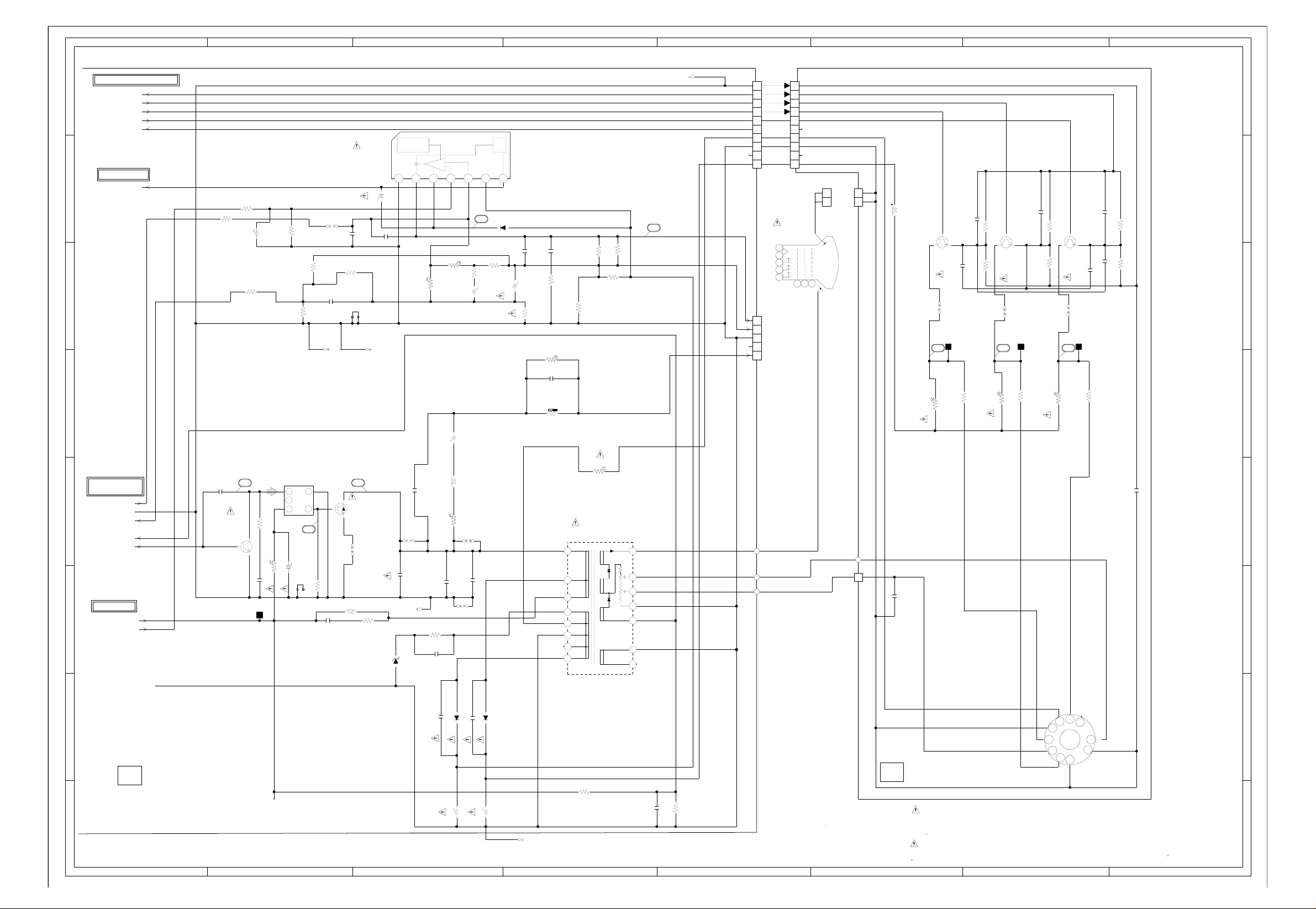
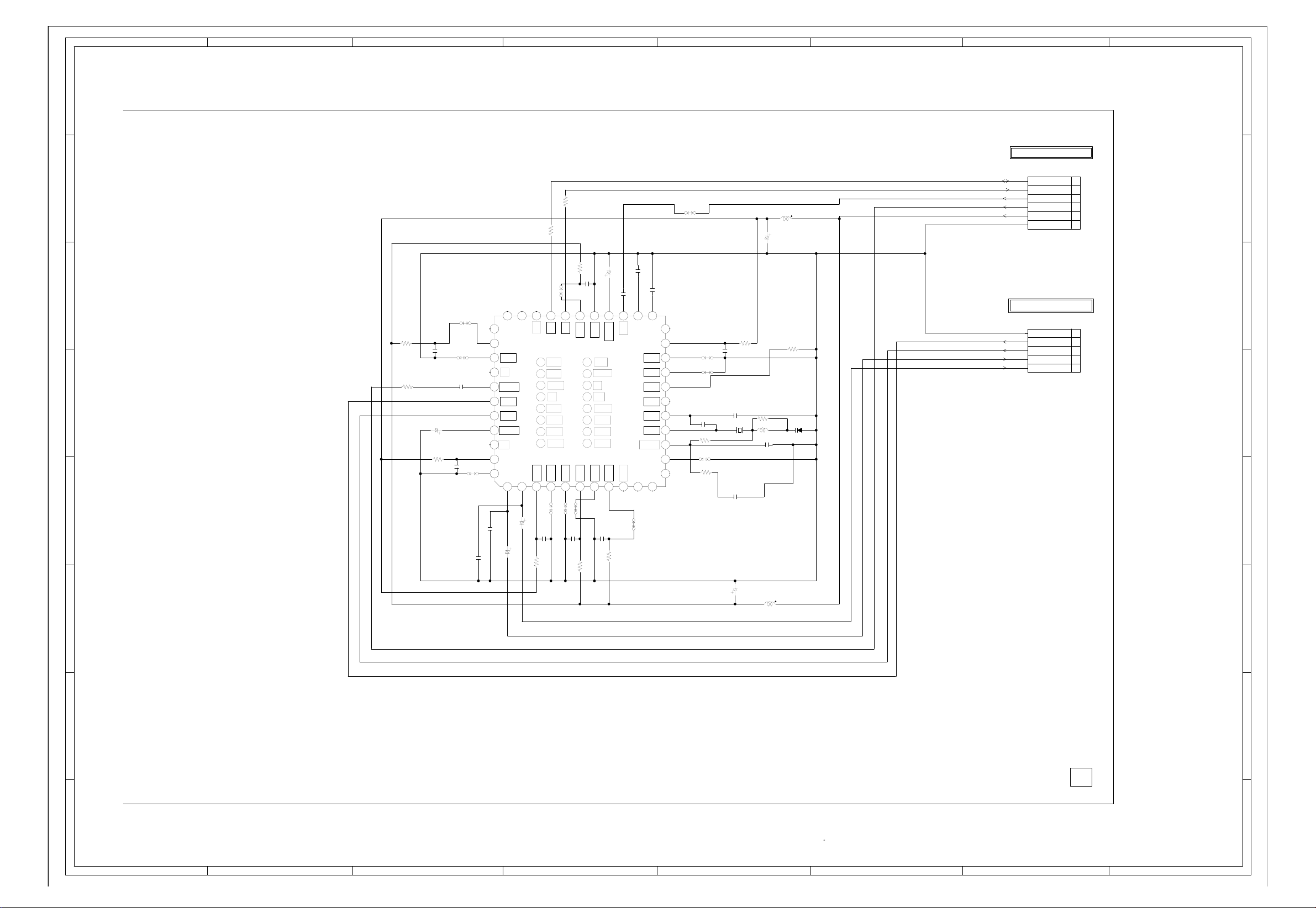
Components Location Guide