NATIONAL
TAPE
RECORDER
SERVICE
MANUAL
Sea
ase
ae
eae
rGsicat
a
eee
7
MODEL
RQ-152S8
A.C D.C
2
SOURCE
TAPE
RECORDER
CONTENTS
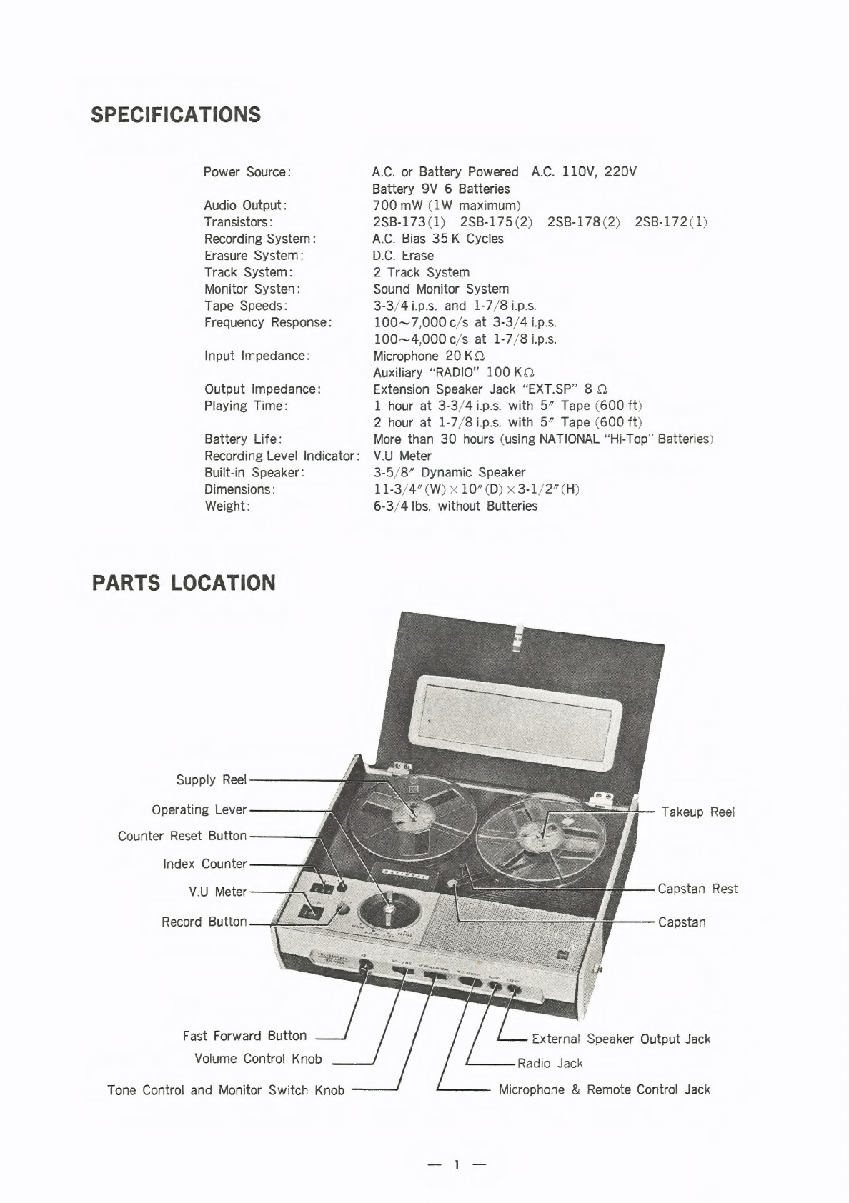
SPECIFICATIONS:
a2c2.roseen
tcc
cnien
crnets:
asaen
eure
coi
ae
uatinentscensnouresenmnsaeisess
PARTS
LOCATION
xtacsesecces
cess
cconsesremensents
usa
saescncenenemslansinminamedetesn
cc
BLOCK
DIAGRAM
OF
ELECTRICAL
CIRCUITS
........-.eeeeesee
eee
eee
eee
eee
eee
ees
DISASSEMBLY]
INSTRUCTION)
sizccses-tecssnnssccunomcesscrecenonsienemmecenesses
se
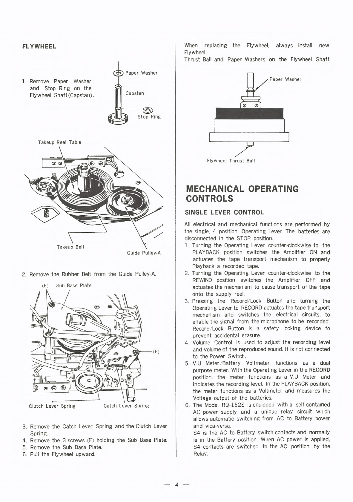
MECHANICAL
OPERATING
CONTROLG.............::ccecee
eee
eeecee
tence
eens
nee
een
ens
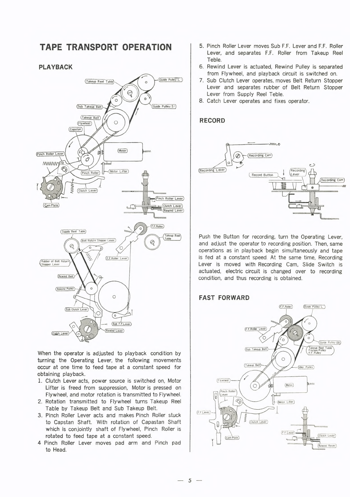
TAPE
TRANSPORT
OPERATION:
eticcescuss.crcore
esuacioscsssnsesanascinrenecencnss
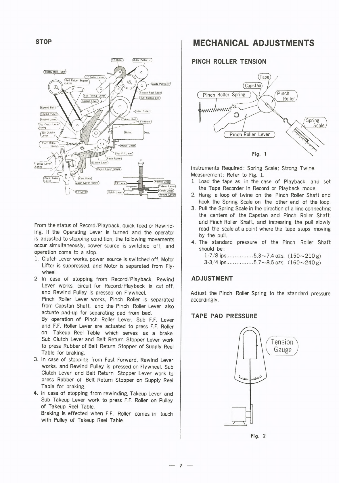
MECHANICAL
ADJUSTMENTS)
ann.
socacsceces
cnsscsnaneccstearereesentctinecererssr
anes
AMPLIFIER
ADJUSTMENTS
05.4
-ler-ciscenessssaciymossuesncnoscacmemnseoreenrtaiaecois:
TROUBLE
“SHOOTING:
GUIDE.
-.cca-crens
ccc
ceeanenceacanesbecaeaeuemenenenceneanee
REPLACEMENT
PARES
LISI
c2ec.c5iee.s2-c:csesecscnsn
ssasseennece
sss
seeeeamee
ree
stese
CIRCUIT
ABOARD
wees
ecco
secrecccanesancecnicea
ee
aanssea:
a
cslgansosusow
anacus
vseeeeviemmaines
GABINEN:
PARTSic-ceececaescct
strcess
ete
n
eace
sec
acenunia
swan
gscueee-manecienare
sevietsesen
EXPLODED
VIEWS:
ccc
csececee
us
otaecer
cnteeu
neice
ace
cacosameeesuie
mana
ara
euenmeneencsees
WIRING
CONNECTION
DIAGRAM
.............:.sccccnseeeeseeeeeeee
tea
eeeoeeecesunens
SCHEMATIG
‘CIRCUIT
DIAGRAM)
cizs.ae
ese
sosceccecac
ties
Sos
coca
ectonecen
estes
oecsien’
ELECTRICAL
PARTS:
LOCATION
sisecnt
siocivcseccesasesa.n
se
oceeecmemeceneneecenneess
AGGESSORIES),
Secccneseesooace
to
semencectsceeuns
sens
cates
ceniccatecieueunagiscsscee
COMPONENTEPAGKING
sxe
tosses
eens
tte
eens
enere
te
ememnae
se
colecetaaetar
ers
MATSUSHITA
ELECTRIC
JAPAN