Matsushita Electric SB-PM53P User manual

ORDER NO. MD0512489C1
A6
Speaker System
SB-PM53P
Colour
(M)... Wood Type
SPECIFICATIONS
Specification
Type 2 way, 2 speaker system
Speaker(s)
Woofer 10 cm (4”) cone type (6 )
Tweeter 6 cm (2-3/8”) cone type (6 )
Impedance 6
Input power (IEC)
High 90 W (Max)
Low 90 W (Max)
Output sound pressure 80 dB/W (1.0 m)
Crossover over frequency 2.2 kHz
Frequency range 45 Hz to 35 kHz (-16 dB)
50 Hz to 31 kHz (-10 dB)
Dimensions (W x H x D) 144 x 249 x 200 mm
(5-11/16” x 9-13/16” x 7-7/8”)
Mass 1.9 kg (4.2 Ib.)
Notes :
1. Specifications are subject to change without notice.
Mass and dimensions are approximate.
2. Total harmonic distortion is measured by the digital spectrum
analyzer.
3.The labels “HIGH” and “LOW” on the rear or the speakers refer
to High frequency and Low frequency.
1

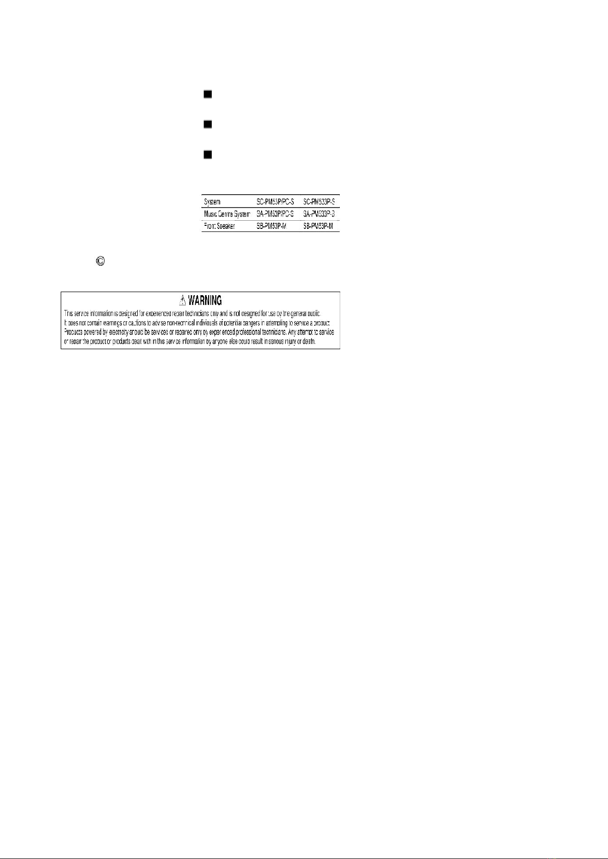
System : SC-PM53P-S Music Center : SA-PM53P-S
Front Speaker : SB-PM53P-M
System : SC-PM53PC-S Music Center : SA-PM53PC-S
Front Speaker : SB-PM53P-M
System : SC-PM533P-S Music Center : SA-PM533P-S
Front Speaker : SB-PM53P-M
2005 Matsushita Electric Industrial Co. Ltd.. All rights reserved.
Unauthorized copying and distribution is a violation of law.
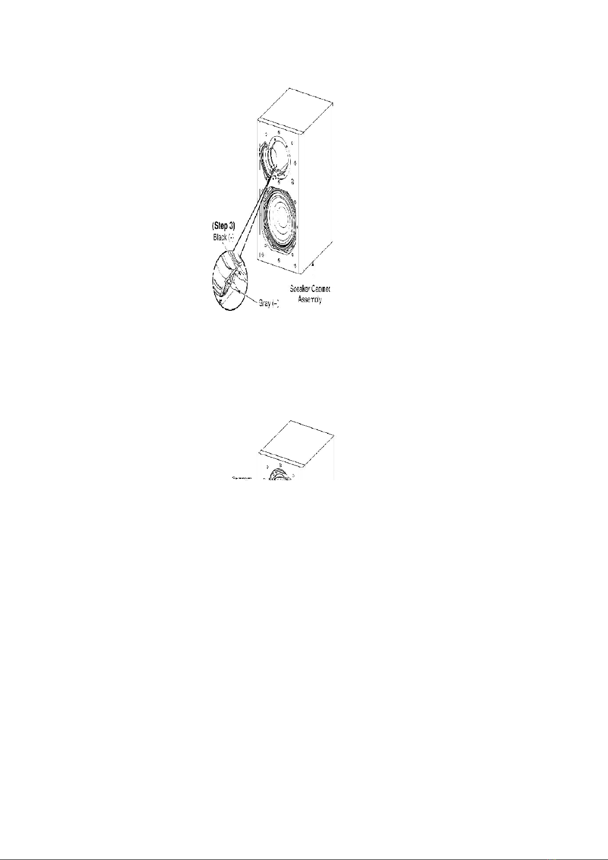
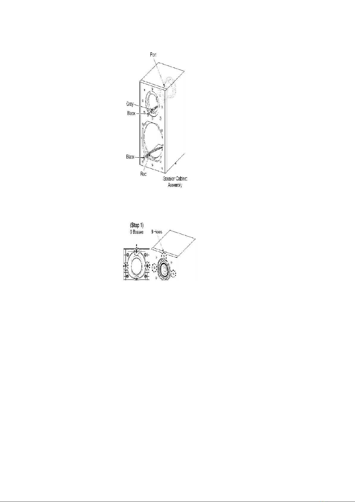
1. Assembling and Disassembling
“ATTENTION SERVICER”
Some chassis components may have sharp edges. Be careful when disassembling and servicing.
1. This section describes procedures for checking the operation of the
major printed circuit boards and replacing the main components.
2. For reassembly after operation checks or replacement, reverse the
respective procedures.
Special reassembly procedures are described only when required.
3. Select items from the following index when checks or replacement are
required.
4. Refer to the Parts No. on the page of “Parts Location and Replacement
Parts List” (Section 5), if necessary.
2

Below is the list of disassembly sections
- Disassembly of Net Frame Assembly
- Disassembly of Front Panel
- Disassembly of Tweeter
- Disassembly of Speaker
- Disassembly of Speaker Cabinet Assembly
1.1. Disassembly flow chart
The following chart is the procedure for disassembling the casing and inside parts for internal
inspection when carrying out the servicing.
To assemble the unit, reverse the steps shown in the chart as below.
3

1.2. Disassembly of Net Frame Assembly
Step 1: Remove Net Frame Assembly as arrow shown .
Step 2: Remove Gray Net Holder from Net Frame Assembly.
1.3. Disassembly of Front Panel
Follow (step 1) in item 1.2.
4

Step 1: Remove 4 screws from Front Panel.
Step 2: Insert a small Steel rule into the grooves of the Front Panel and lift up a little bit to make a gap
allowance between the Front Panel and Speaker Cabinet Assembly as arrow shown.
5

Step 3: Insert a flathead screwdriver into the groove as shown. Ensure that the screwdriver is above the
small Steel rule.
Step 4: At the boss area, push up as arrow shown to open the bosses.
Caution:
Do not exert strong force as it may damage Front Panel.
6

1.4. Disassembly of Tweeter
Follow (step 1) in item 1.2.
Follow (step 1) to (step 4) in item 1.3.
Step 1: Remove 2 screws from Tweeter.
Step 2: Remove Tweeter by inserting the steel rule in between the Tweeter and Speaker Cabinet
Assembly as arrow shown.
7

Step 3: Remove the Tweeter by detaching the (+) Gray and (-) Black wires.
1.5. Disassembly of Speaker
Follow (step 1) in item 1.2.
Follow (step 1) to (step 4) in item 1.3.
Step 1: Remove 4 screws from Speaker.
8

Step 2: Remove Speaker by inserting the steel rule in between the Speaker and Speaker Cabinet
Assembly as arrow shown.
Step 3: Remove the Speaker by detaching the (+) Red and (-) Black wires.
1.6. Disassembly of Speaker Cabinet Assembly
Follow (step 1) in item 1.2.
Follow (step 1) to (step 4) in item 1.3.
Follow (step 1) to (step 3) in item 1.4.
Follow (step 1) to (step 3) in item 1.5.
9

1.7. Assembly of Speaker Unit
Step 1: Scrape off using the scriber and clean up the remaining glue at the 9 bosses and 9 holes of the
Front Panel and Speaker Cabinet Assembly and replace with new glue.
10

Step 2: Fix the Front Panel firmly back to the Speaker Cabinet Assembly.
2. Connection of the Speaker Cables
- Be sure to connect speaker cables before connecting the AC power
supply cord.
- The load impedance of any speaker used with this unit must be 6 .
- Be sure to connect the cable from the right speaker to the right terminal
and the cable from the left speaker to the left terminal.
1. Twist and pull off the vinyl tip of the speaker cords. If the speaker
cords do not have vinyl tips, connect them directly to the terminals.
Make sure the bare ends of the wires are not unravelled.
2. Insert the wire to the rear panel of the unit and close the lever.
Notes :
- To prevent damage to circuitry, never short-circuit positive (+) and
negative (-) speaker wires.
- Be sure to connect only positive (red/gray) wires to positive (+)
terminals and negative (black/blue) wires to negative (-) terminals.
Placement
Speakers are designed identically so that no left or right channel orientation is necessary.
11

Connection
Use only the supplied speakers
The combination of the main unit and speakers provide the best sound. Using other speakers can
damage the unit and sound quality will be negatively affected.
Note
- Keep your speakers at least 10 mm (13/32”) away from the system for
proper ventilation.
- These speakers do not have magnetic shielding. Do not place them near
televisions, personal computers or other devices easily influenced by
magnetism.
- To avoid damage to the speakers, do not touch the speaker cones if you
have taken the nets off.
3. Connection of the Wiring Diagram
12

4. Cabinet Parts Location
4.1. Exploded view
4.2. Packaging
13

5. Replacement Parts List
Notes :
- Important safety notice :
When replacing any of these components, be sure to use only
manufacturer’s specified parts shown in the parts list.
- [M] markings in the Remarks columns indicates parts supplied by
PAVCSG.
14

Ref. No. Part No. Part Name & Description Remarks
CABINET AND CHASSIS
1RFKHBPM53P-M SPEAKER CAB.ASS’Y [M]
1-1 RKA0072-KJ LEG CUSHION [M]
2RYBV0041 NET FRAME ASS’Y [M]
2-1 RMG0520-H NET CATCHER [M]
3XTB4+16AFJK SCREW [M]
4RGNV0177-K SPEC LABEL [M]
5RHDV40004 SCREW [M]
6RMQ0621 EVA PACKING (TWEETER) [M]
7RMQV0054 EVA PACKING (WOOFER) [M]
9RGPV0083-S FRONT PANEL [M]
CAPACITOR
C1 ECA1HAY4R7S 4.7uf 50V [M]
PACKING MATERIALS
P1 RPNV0097 POLYFOAM [M]
P2 RPF0420 MIRAMAT BAG [M]
SPEAKERS
SP1 EAS10PL624A SPEAKER [M]
SP2 EAS6PH124C TWEETER UNIT [M]
FLE0512W/S
15
This manual suits for next models
3
Table of contents