Mattei BLADE 15 Series Specification sheet

INSTRUCTION, USE AND
MAINTENANCE MANUAL
Models
BLADE 15-18-22
BLADE 15-18-22 i
Versions
Standard
Plus
ENGLISH
BLADE
Translation of the original
instructions in ITALIAN
TI215G0010
rif. TDA0150017

BLADE
II TI215G0010
The present manual, written in English, is the ocial
translation of the manual in Italian, chosen as reference
language by Ing. ENEA MATTEI SpA.
The paper copy will be available for over 10 years after
end of production of the machine to which it refers.
The content of this document cannot be used,
reproduced or disclosed to third parties without the
explicit written consent of Ing. ENEA MATTEI S.p.A.
Ing. ENEA MATTEI S.p.A. reserves the right to modify
the characteristics of the machine subject of this
document without prior notice.
Copyright 04/2016 by Ing. ENEA MATTEI S.p.A.
This Instruction Manual meets all the requirements of
Directive CE. It is to be considered valid for both the
machines with the CE Marking and those without it.
Important note
This manual should always be used together with the
“MaestroXB User’s Manual”.
Forward

BLADE
III
TI215G0010
General index
Indice
FORWARD .................................................................................................................................................................... II
GENERAL INFORMATION ........................................................................................................................................ 11
Symbols in the manual...............................................................................................................................................................................................................1-1
Purpose of document.................................................................................................................................................................................................................1-2
Required qualications for operators ...................................................................................................................................................................................1-3
Identication data of the manufacturer and the machine and the location of the nameplate“CE MARKING”........................................1-4
General notes on delivery .........................................................................................................................................................................................................1-5
Final inspection.............................................................................................................................................................................................................................1-5
Safety warnings ............................................................................................................................................................................................................................1-5
Setting at the customer’s expense.........................................................................................................................................................................................1-7
Instructions on how to request interventions...................................................................................................................................................................1-7
Instructions on how to order spare parts ...........................................................................................................................................................................1-7
GENERAL INFORMATION SAFETY ....................................................................................................................... 21
Danger and residual risks..........................................................................................................................................................................................................2-1
Responsibility ................................................................................................................................................................................................................................2-3
Description of pictograms ........................................................................................................................................................................................................2-3
DESCRIPTION OF THE MACHINE ............................................................................................................................ 31
General description of the machine......................................................................................................................................................................................3-1
Technical data and overall dimensions ................................................................................................................................................................................3-7
TRASPORTATION AND HANDLING ....................................................................................................................... 41
INSTALLATION.......................................................................................................................................................... 51
The machine position ................................................................................................................................................................................................................5-1
Electrical connection...................................................................................................................................................................................................................5-2
Connection to the air network ...............................................................................................................................................................................................5-2
Dimensions of compressed air distribution piping .........................................................................................................................................................5-3
Heat recovery.................................................................................................................................................................................................................................5-4
SAFETY DEVICES...................................................................................................................................................... 61
Emergency push-button ...........................................................................................................................................................................................................6-1
Safety valve.....................................................................................................................................................................................................................................6-1
Servovalve.......................................................................................................................................................................................................................................6-1
COMMANDS AND CONTROL................................................................................................................................... 71
MaestroXB .........................................................................................................................................................................................................................................7-1
HOW TO USE THE MACHINE ................................................................................................................................... 81
Foreword .........................................................................................................................................................................................................................................8-1
Operation modes (Blade version)...........................................................................................................................................................................................8-1
Operation modes (Blade i version).........................................................................................................................................................................................8-4

BLADE
IV TI215G0010
General index
Controller MaestroXB ....................................................................................................................................................................................................................8-4
Operational failures.....................................................................................................................................................................................................................8-4
Starting ............................................................................................................................................................................................................................................8-5
Stop ...................................................................................................................................................................................................................................................8-5
MAINTENANCE ........................................................................................................................................................ 91
Suggestions on maintenance..................................................................................................................................................................................................9-1
Periodic maintenance table......................................................................................................................................................................................................9-2
Maintenance kit ............................................................................................................................................................................................................................9-3
Check of oil level...........................................................................................................................................................................................................................9-4
Cleaning and/or replacing the air suction lter ................................................................................................................................................................9-4
Cleaning the air/oil radiator ....................................................................................................................................................................................................9-4
Cleaning the pre-lters ..............................................................................................................................................................................................................9-4
Replacement of oil lter element...........................................................................................................................................................................................9-4
Replacement of the air-oil separator lter element.........................................................................................................................................................9-4
Replacement of the elastic element......................................................................................................................................................................................9-5
LUBRICANTS........................................................................................................................................................... 101
Oil change.................................................................................................................................................................................................................................... 10-1
Warning......................................................................................................................................................................................................................................... 10-2
General.......................................................................................................................................................................................................................................... 10-2
Mattei lubricants........................................................................................................................................................................................................................ 10-2
Safety precautions .................................................................................................................................................................................................................... 10-3
Storage and treatment of oils............................................................................................................................................................................................... 10-3
TROUBLESHOOTING.............................................................................................................................................. 111
General.......................................................................................................................................................................................................................................... 11-1
Problem - Cause - Solution .................................................................................................................................................................................................... 11-1
Inverter malfunctions .............................................................................................................................................................................................................. 11-2
THE ELECTRICAL MOTOR ......................................................................................................................................121
General.......................................................................................................................................................................................................................................... 12-1
Lubrication ................................................................................................................................................................................................................................ 12-1
Cooling.......................................................................................................................................................................................................................................... 12-1
Abnormal noises........................................................................................................................................................................................................................ 12-1
Electrical checks......................................................................................................................................................................................................................... 12-1
STORAGE DECOMMISSIONING AND DISMANTLING .......................................................................................131
Storage.......................................................................................................................................................................................................................................... 13-1
Decommissioning..................................................................................................................................................................................................................... 13-1
Dismantling................................................................................................................................................................................................................................. 13-1
Residual risks after deactivation .......................................................................................................................................................................................... 13-1
CONDENSATE UNLOAD IN OPTIONAL KIT ..........................................................................................................141
Cleaning the drain solenoid valve lter ............................................................................................................................................................................ 14-1

BLADE
V
TI215G0010
ATTACHMENTS....................................................................................................................................................... 151
Form to request technical service ....................................................................................................................................................................................... 15-1
Form to request spare parts .................................................................................................................................................................................................. 15-2
Technical data sheets............................................................................................................................................................................................................... 15-3
General index

BLADE
1-1 TI215G0010
General information
SYMBOLS IN THE MANUAL
In this manual some symbols are used that to attract
the reader’s attention and underline some particularly
important aspects of the treatment.
!
Danger
It indicates a danger with the risk for accident,
even fatal, for the user. Pay careful attention to
text block with this symbol.
!Warning
It warns against a possible deterioration of the
m hine or personal item of the user.
F Notice
It shows either a notice or a note on the key
functions or useful information.
Further information
This symbol introduces text blocks containing
further information. This information has no
direct relationship with the description of a
function or with procedure development.They
could be cross-references to other documents
or other sections of this manual.
The table below gives the list and describes the meaning
of the dierent symbols used.
Damage risk
It indicates a high damage risk of a piece, for
example, using a wrong tool or by mounting
something with the incorrect procedure.
Visual check
It recommends the reader to carry out a visual
check. This symbol can also be found in the
instructions for use. The user is required to
read a measure value, to check some warning
signs, etc.
Acoustic check
It recommends the reader to carry out a sound
acoustic check. This symbol can also be found
in theinstructions for use. The user is required
to listen to an operational noise.

BLADE
1-2
TI215G0010
General information
PURPOSE OF DOCUMENT
This manual contains the technical characteristics,
the performance, the transportation and installation
rules, the instructions for use, and the preventive and
corrective maintenance operations of the machine
manufactured by Ing. ENEA MATTEI S.p.A.
NOTE
This manual should be considered an
integral part of the machine, and should
stay with it during the entire life span of the
equipment.
Keep this manual and all of the attached
documents in a place easily accessible
to all sta in charge of the control or
the maintenance of the machine. Ing.
ENEA MATTEI S.p.A. reserves the right to
subject the supply of further copies to the
repayment of charges and the acceptance
of special provisions with respect to the
ligitimate defense of intellectual, patent,
and executive identity and functional
property of the product and/or its parts.
It is understood that forwarding all or part of
this manual to third parties is not tolerated
unless with the prior written consent of Ing.
ENEA MATTEI S.p.A. for both the text, the
illustrations and the diagrams attached.
Ing. ENEA MATTEI S.p.A. reserves the right
to make changes without prior notice.
Any change, supplement or suppresion of
elements, components, functions or cycles
of the machine, not previously agreed
upon with Ing. ENEA MATTEI S.p.A. releases
the manufacturer from any responsibility
whatsoever.
This manual is for the user and the service engineer of
the machine, and it aims at supplying them with the
basic technical data typical of the system, a technical
description of the several operating groups that form
it as well as the essential use procedures and the
information necessary to perform preventive and
corrective maintenance.
This manual is for sta with a sound knowledge of the
processing technique, of mechanical and electrical
diagrams, and is for both those in charge for the use of
the machine and the service engineers.
This manual is an integral part of the machine and
contains information that aims at granting all sta safe
working conditions and guaranteeing perfect eciency
during the life span of the machine.
For a correct use of the machine, it is assumed that the
working environment is adequate to current regulations
concerning safety and hygiene.
DIRECTIVES AND TECHNICAL STANDARDS APPLIED
The machine has been designed, made, and inspected
in compliance with the “safety and health essential
requirements” stated in attachment I to the European
Directive CE.The list below gives the reference Standards
used by Ing. ENEA MATTEI S.p.A. to design, make, and to
make the nal inspection of the machine.
LIST OF DIRECTIVES AND TECHNICAL HARMONIZED
STANDARDS
MACHINERY DIRECTIVE CE
ELECTROMAGNETIC COMPATIBILITY (EMC) DIRECTIVE CE
LOW VOLTAGE DIRECTIVE CE
EN 1012-1 Compressors and vacuum pumps - Safety
Requirements - Compressors
F

BLADE
1-3 TI215G0010
General information
REQUIRED QUALIFICATIONS FOR OPERATORS
The operator in charge of the operation or the
maintenance of the machine should have all the
professional requirements specic to each foreseen
operation. The operator should be trained and aware of
his responsibilities.
Below is the description of the professional proles
concerning the operators in charge of the machine.
Entry level machine operator
(Qualication 1)
Qualied sta able to carry out simple
tasks, i.e. to operate the machine with the
use of controls on the push-button, and
to carry out typical simple functions of
adjustments, start or stop.
Second level machine operator
(Qualication 2)
Qualied sta able to carry out the
task of qualication 1 and also to
operate the machine with disconnected
safety protections to perform specic
adjustments, start or stop functions.
FIMPORTANT
This qualication includes those responsibilities
typically subdivided into two separate
qualications. For the operator in charge of our
machines, a specialization course is held to train
the operator to be able to perform all of the
actions necessary to operate the machine even
with some of the protections disconnected.
However, this requires a certain competence by
the operator and extreme care by the manager
of the factory so that the said operator carries
out only the established operations.
Mechanical Service Engineer
A qualied engineer able to operate the
machine under normal conditions, to
operate it with disconnected protections,
to intervene on mechanical parts to carry
out all adjustments, carry out maintenance
and all of the necessary repairs. This person
is not empowered to carry out interventions
on electrical systems with live voltage.
Electrical Service Engineer
A qualied engineer able to operate the
machine under normal conditions, to
operate it with disconnected protections.
He/she is in charge of all electrical
adjustments, maintenance and repair. He/
she is able to operate with live voltage
inside cabins and shunt boxes.
The Manufacturer’s Engineer
A qualied engineer from the manufacturer
to perform complex operations in special
situations or according to that which has
been agreed upon with the user.

BLADE
1-4
TI215G0010
IDENTIFICATION DATA OF THE MANUFACTURER AND THE MACHINE AND THE LOCATION
OF THE NAMEPLATE “CE MARKING”
Ing. ENEA MATTEI S.p.A. is identied as the machine’s manufacturer in conformity with the laws in force with the
following acts:
Declaration of conformity
CE Marking
Instruction Manual
A specic plate on the machine gives the following indelible information on the
CE MARKING:
Model
Code
Serial number
Year of manufacture
Delivery
Pressure
Power
Number of runs
Dryer
Tank capacity
Total weight
Name and address of manufacturer
The “CE MARKING” plate has been applied at the base of the machine.
The relevant “DECLARATION OF CONFORMITY” has been attached.
It is forbidden to remove the “CE MARKING” plate and/or exchange it for other plates of machines of the same model
supplied to the Customer or the operator. Should the “CE MARKING” plate be accidentally damaged or removed from
machine, the customer is required to inform the Company.
General information

BLADE
1-5 TI215G0010
General information
GENERAL NOTES ON DELIVERY
Upon receipt of the machine please check that:
– the supply complies with the order specication;
– machine has not suered any damage due to
transportation or other reasons.
In the event of damage or missing parts, report it
immediately and in detail to the forwarding agent or
Ing. ENEA MATTEI S.p.A.
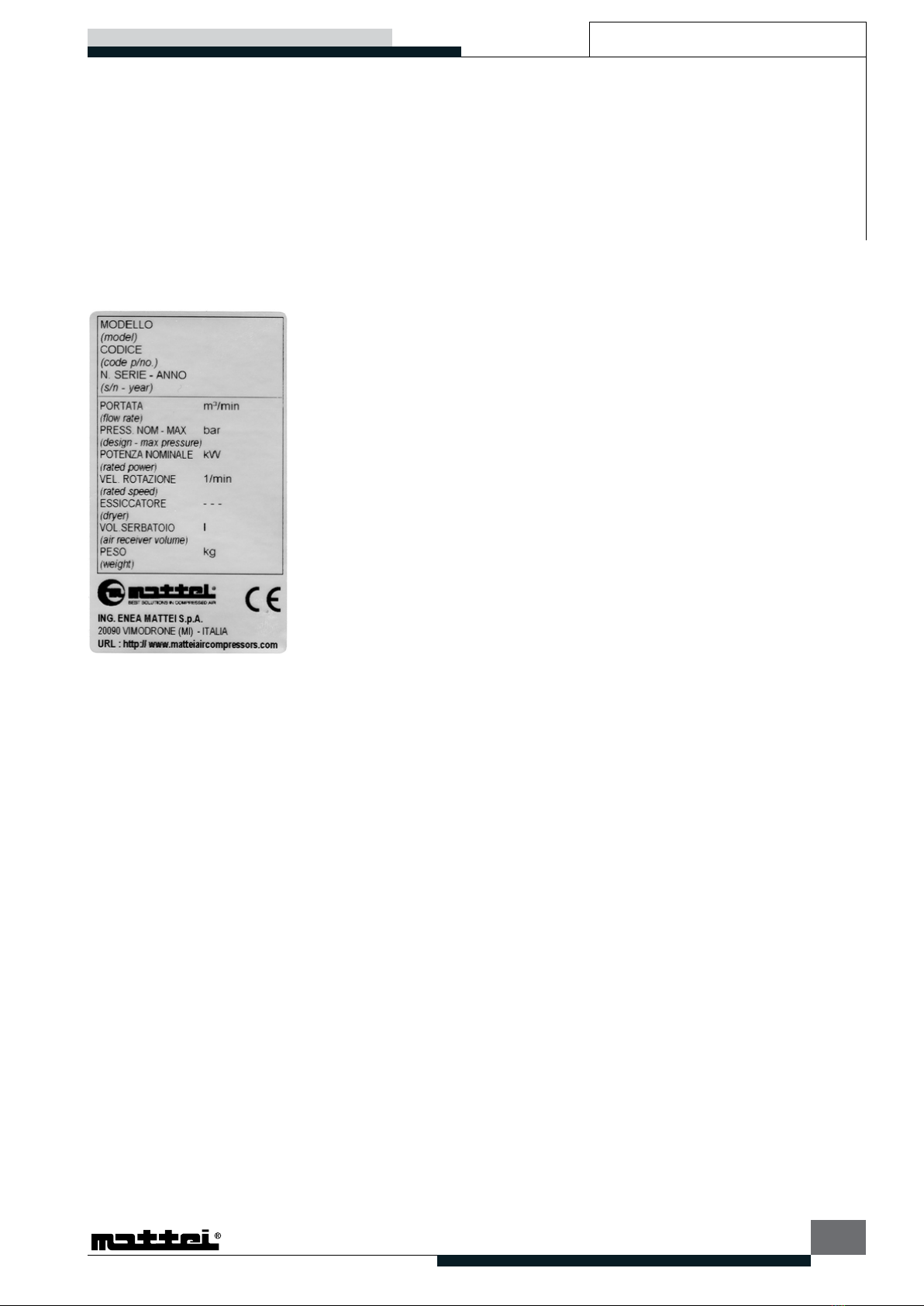
ALWAYS STATE THE MACHINE SERIAL NUMBER ASWELL
AS THE PRINT NUMBER OR THIS CATALOGUE WHEN
MAKING ANY REQUEST TO Ing. ENEA MATTEI S.p.A.
OR ONE OF THEIR SERVICE CENTRES.
FINAL INSPECTION
The manufacturer carries out the nal inspection of
the machine directly, during the production phases, in
compliance with the company quality system. Ing. ENEA
MATTEI S.p.A. is responsible for the machine under its
original conguration.
Ing. ENEA MATTEI S.p.A. refuses any responsibility for
improper use of the machine, for damages due to
operations which are not described in this manual or
unreasonable jobs.
SAFETY WARNINGS
The nal user should comply with the instructions given
by the Seller concerning:
– safety devices already installed on the machine;
– instructions for the correct machine installation;
– correct use and periodic maintenance of all of the
machine components, including the safety devices;
– regulations of current laws.
The following safety precautions dene both the
behaviour and obligations to be observed when carrying
out the activities listed in the manual, the instructions
for the machine use and the way how to operate under
safety conditions, for the sta and the surrounding
environment.
Machinary Directive
Machinery Directive means the CE DIRECTIVE OF THE
EUROPEAN PARLIAMENT AND COUNCIL dated 17 May
2006.
Machine
Machine means the functional assembly composed
of: control unit, processing unit, working and resting
equipment, systems (electrical, pneumatic, hydraulic,
cooling, lubrication systems) and any group completing
the system functionality.
Working area
Working area means the protected volume limited
by guards to prevent injuries and aimed at operation
during the machine processing.
Authorized sta
Authorized sta means personnel duly trained and
appointed to perform the activities listed below and that
make up the operating instructions for the machine.
Appointed sta
Appointed sta means the personnel who, although not
participating materially in the work, supervise the work
of others, for example, the responsible engineer.
Transport
Transportation means all those operations regarding
the handling of the machinery or a part of it.
Installation
Installation means the mechanical, electrical, and uid
plant engineering integration of the machine within
a production reality, in compliance with the specied
requirements.
Commissioning
Commissioning means the functional check of the
machine installed.
Operation
Operation means the mode in which the machine
produces compressed air according to regulations,
settings, and commands inserted by the control device.
Decommissioning
Decommissioning means the mechanical and electrical
removal of the machine from a production area.
Dismantling
Dismantling means the dismantling and discarding of
machine components.
Maintenance and repair
Maintenance and repair means the regular check and/
or replacement of parts or components of the machine
and any action aiming at identifying the origin of a
failure that concludes with the resetting of the machine
to the functional design conditions.

BLADE
1-6
TI215G0010
General information
Improper use
Improper use is the use of the machine outside the limits
specied in the technical documents.
Applicability
The regulations should be applied when carrying out
one of the following activities:
– Transport, Installation and Setting up;
– Manual Mode;
– Continuous Mode;
– Decommissioning and dismantling;
– Maintenance and repair that compose the use
procedures envisaged for the machine.
Installation and setting up
The installation and setting up of the machine are
permitted only by the authorized sta.
During installation, handle the machine components
as recommended in this manual. Should lifting be
necessary, verify rst the correct xture of devices
specically for lifting and use adequate slings and
equipment. The machine installation area should be as
free as possible from any material that could prevent
or limit it from being seen. Check that all the machine
safety devices are correctly xed and that no moving
or loose parts are present. Also check the soundness
of the components of the control unit. Connect the
pneumatic machine to the air distribution network
and carefully verify that the pressure value is correctly
set. Verify the consistency between the voltage set
on power transformers and the voltage value of the
energy distribution net. Before connecting the machine
electrical system, check that the sectioning device
of the power supply be blocked in the open position.
Verify that the anti-accident guards have been correctly
installed and are in good working order.
F
The machine safety is not guaranteed in case
of removal, by-pass or tampering of safety
devices on the machine.
To stop the machine in an emergency, press on the
emergency stop button.
Operating the machine
Only authorized and duly trained sta or at least with
a sucient technical experience should operate the
machine. The sta in charge of the operating the system
should be aware that the knowledge and application
of safety regulations is an integral part of their job. Any
non-qualied sta should not access the operating
area and the machine control panel when the system
is running. Before starting the machine, carry out the
following operations:
– carefully read the technical documents;
– collect information on the operation and the position
of emergency stop devices on the machine;
– know which guards and safety devices are on the
machine, their position and their operation.
It is forbidden to either disconnect or partially remove
the guards and the safety devices. The same regulation
applies to the danger signals in particular areas of the
machine. It is strictly forbidden to access the working
area and the control and power cabins during operation,
even partial, of the equipment or immediately after it is
turned o.
Guards and safety devices should be kept in perfect
condition so as to allow for their correction function¬ing.
In the event of failure, they should be immediately
repaired or replaced.
The unauthorized use of commercial parts and
accessories for the guards and safety devices can lead to
malfunctioning and the risk of dangerous situations for
the operating sta.
Decommissioning and dismantlign
Only authorized sta is allowed to decommission and
remove the machine.
– Before decommissioning, it is necessary to disconnect
the sectioning device power supply and to block it in
the open position;
– discharge oils and uids, remove all moving parts;
– disconnect the power supply cable from the
sectioning device by cutting o the power wires rst
and then the ground one;
– disconnect the power supply cable from the machine
main switch and remove it;
– disconnect the machine pneumatic equipment from
the air distribution network;
– remove the machine from the working area while
applying all regulations given in this manual;
– before lifting, verify the correct use of lifting devices
and use only suitable equipment.
Waste disposal should be performed in compliance
with the laws in force in the Country where the machine
has been installed. Installation, setting up and use of
compressor should be carried out in compliance with
the standards and the rules in force concerning safety
at work.
The owner of the machine is responsible for its good
maintenance, an essential condition to ensure operation
in total safety. Those machine parts that, due to improper
use, wear and tear, do not guarantee the safe operation
should be timely replaced. Only duly trained authorized
and qualied sta should perform the installation,
use, maintenance, and repairs. In case of discrepancies

BLADE
1-7 TI215G0010
between the instructions given in this manual and those
set out by the law in force concerning safety, it is highly
recommended to apply the more restrictive ones.
Maintenance and repair
Only authorized sta is allow to carry out maintenance,
troubleshooting, and repairs. Any maintenance and
repair in progress should be indicated with a specic
sign stating the maintenance condition, and placed on
the control panel of the control unit until completion
of the operation even if temporarily interrupted. All
operations concerning its installation, maintenance or
replacement of components on either the machine or
the control unit should be performed with the system
turned o. Hence, the main switch should be on OFF
(OPEN) and blocked with the safety lock to prevent any
movement in the ON position.
For compressors equipped with INVERTER, before
performing any maintenance job, wait at least 5
minutes after you have disconnected the electricity
supply.
The sta in charge of maintenance, before intervening,
should rst check that the following conditions exist:
– possible tanks under pressure have been discharged.
The sta in charge of maintenance, before intervening
on pneumatic or lubricating systems and specically
on piping, tanks, hoses, and other components under
pressure should correctly reduce the inner pressure
value of the equipment to be investigated to the room
pressure value. Dysfunctional components should be
replaced with others with the same code. If, during
troubleshooting, it should be necessary to carry out the
interventions with the control unit and the machine
supplied, all precautions should be taken as required
by the safety standards to operate under dangerous
voltages and with moving parts. At the end of the
maintenance and troubleshooting interventions, all
disconnected safety devices must be reset. Maintenance,
repair, and troubleshooting should be completed with
the verication of the correct operation of the machine
and of all of its safety devices.
SETTING AT THE CUSTOMER’S EXPENSE
Except in the case of possible dierent contractual
agreements, the following items are normally at the
customer’s expense:
– room preparation (including building work such as
the laying of foundations or canalizations, if required,
etc.);
– anti-slip, leveled ooring;
– preparation of both the place of installation and
the machine installation itself whilst observing the
dimensions set out in the layout;
– preparation of auxiliary services appropriate to the
equipment requirements (such as electrical network,
pneumatic network, etc.);
– preparation of electrical equipment in compliance to
Directive CE;
– adequate lighting complying with standard EN
60204-1;
– any safety devices before and after the energy supply
lines (such as dierential switches, ground systems,
safety valves, etc.) as may be required by the laws in
force in country of installation;
– ground equipment complying with standard CEI 64-
8.
INSTRUCTIONS ON HOW TO REQUEST
INTERVENTIONS
For any type of information on the use, the maintenance,
the installation etc. Ing. ENEA MATTEI S.p.A. is always
available to meet the Purchaser’s requests. However,
any enquiries be made in clear terms, with references to
this manual and always stating the data on the machine
id plate. For any communication with the service center,
always indicate the type of machine, its serial number,
and the year of manufacture, which help identify every
machine and, whenever possible, specify the nature of
the detected problem or the defect indicated by the
machine such as: of an electrical, mechanical kind or
in terms of work quality, while describing the problem
on a copy of the “FORM FOR TECHNICAL SERVICE
REQUEST” attached to this manual.
Contact our local service department closest to you or
the central Italian oce.
INSTRUCTIONS ON HOW TO ORDER SPARE PARTS
The machine may over a period of time require the
replacement of those parts subject to wear. To this
purpose, the purchaser can order the parts to be
replaced. It is compulsory to always buy original spare
parts. To order spare parts always indicate with the
maximum accuracy the following:
– Type and model of machine
– Serial number
– Exact name of the part in question
– Code and/or reference (if available)
– Required quantity
To simplify and speed up the delivery of spare parts, it
is recommended to forward orders by lling in a copy
of the “FORM FOR SPARE PART REQUEST” attached
to this manual and forwarding it to Ing. ENEA MATTEI
S.p.A. or to the closest distributor.
Kits with components for preliminary maintenance
are available.
Please apply to MATTEI for further details.
General information

BLADE
2-1
TI215G0010
General Information - Safety
!
To operate the machine in any operating
condition, including maintenance, it is not
necessary that more than one person be
present. Using more than one person is
superuous and, however, it is not allowed
for safety reasons.
!The employer should instruct the sta on the
accident risks, on safety devices and on the
general rules concerning prevention and
protectionasset outby theEuropean Community
Directives as well as by the laws of the Country
where the machine has been installed.
The operator must know the position and the
operationofall thecommandsandthecharacteristics
of the machine. The operator should also have read
this entire manual.
Only qualied engineers should carry out the
interventions for maintenance after having duly
prepared the machine.
!
Any unauthorized tampering or replacing of
one or more parts of the machine, adopting
accessories that change the use of the
machine and the use of manufacturing
materials other than those recommended in
this manual, can be potential accident risks. It
is strictly forbidden for the machine to be
operated by two people at the same time, one
inside the guards and the other the control
push-button panel.
DANGER AND RESIDUAL RISKS
During design, all the areas at risk were taken into
consideration, and therefore all of the necessary
precautions have been taken to avoid risks to people,
and damage to the machine components. In order to
guarantee both the health and safety of those exposed,
the machine has been provided with special safety
devices:
– EMERGENCY push-button to immediately stop the
machine and STOP devices on the push-button panel
of the control device;
– Fixed guards: these are mounted in areas for exclusive
access for standard maintenance. They are xed with
systems that require specic tools to remove them or
have been screwed in;
– Protection and segregation of the electrical/
electronic equipment of the machine with a
metallic container to avoid accidental contact with
the equipment under voltage in the event that the
metallic container is open; protection of the electrical
cabin: IP 54; protection of inner equipment IP 20
against accidental contact;
– Adequate panels or protection to cover moving
elements;
– Electrical devices to detect supply failures of the
machine and the malfunction of electrical devices of
motors.
!
WARNING !!!
For compressors equipped with INVERTER,
before performing any maintenance job, wait
at least 5 minutes after you have disconnected
the electricity supply.
!
WARNING !!!
Our machine should not be used in areas
where the environment is potentially
explosive.
After having carefully considered all possible risks
concerning the use and maintenance of the machine,
the solutions necessary to remove the risks and limits
the dangers to those exposed have been adopted.
Although the machine is equipped with safety devices,
the following residual risks remain:
– Risk of bruises, tearing, cuts during the handling of
tools and/or elements;
– Risk of bruises during machine intervention.
OPERATION
–The operator should use the personal protection
devices;
– Use the compressor only for the kind of application
for which it has been planned (air compression for
industrial use);
– Before starting, ensure that the compressor has oil;
– For the oil type to be used, please refer to Section 10
of this manual;
– Never operate the compressor if there is a possibility
of inhaling smoke or toxic or ammable vapors;
– Never operate the compressor at pressures higher
than those indicated on the ID plate. The air
delivered directly by the compressor, ltered and
puried from oil, cannot and must not be used for
breathing;
– If hoses are used to distribute air, ensure that they
are of a proper size and adequate to the working
pressure and that they are neither damaged nor
worn. Please remember that rubber hoses should be
replaced at regular intervals;
– Never remove the oil inlet plug when the machine
is running or there is still pressure inside the
compressor: there would be a leak of hot oil;
– Please note that the machine, although it has an
acceptable sound pressure level, can produce a
much higher noise if the room for its installation
is narrow and reverberating. It should be noted

BLADE
2-2 TI215G0010
General Information - Safety
that the machine does not require the continuous
presence of an operator. For protection against noise,
in compliance with local laws in force, if necessary,
specic warning signs should be placed near the
machine and the sta should be equipped with
suitable personal protective means.
INSTALLATION
Besides observing the rules and regulations set out by
competent bodies, it is recommended to consider as
follows:
– The compressor will perform most eciently if
installed in a suitable area that is well ventilated and
far from sources of heat;
– Should any duct be installed for the suction
and cooling of air, always use the data and
recommendations given in Section 5 and preferably
obtain expert advice during the design stage.
– In the event of outdoors installation (discouraged
in very cold climates), the machine must be placed
under a canopy or a cover to protect it from
atmospheric elements;
– Be most careful to prevent any foreign material from
clogging the radiator, thus provoking surges in the
operating temperature;
– The air sucked must be cleaned and free from
ammable vapors that could cause res or explosions;
– As the machine is air cooled, except for versions “R”
(Heat recovery) and “W” (Water cooled), adequate
ventilation must be ensured to prevent it from
overheating and thus avoiding the recirculation of
the expelled hot air;
– The control and safety devices should never be
tampered with;
– If there are one or more compressors installed on one
pneumatic line, it is absolutely necessary that each
be supplied with a gate valve;
– The electrical connections should comply with
the regulations in force. The machines should
be connected to the ground and protected by a
magneto-thermal switch against possible short
circuits.
– It is absolutely necessary that a knife line switch be
installed in front of the compressor.
MAINTENANCE
The person in charge of the eective operation of the
compressor should regularly check that all the operating
instructions relevant to the operation and maintenance
are followed by the operator.
!
WARNING !!!
Fill in the specic“Maintenance register”supplied
with the machine.
Duly trained sta should carry out maintenance only,
with the compressor o and after ensuring that no more
pressure exists inside it. Also insulate the compressor
from the pneumatic equipment. The power supply must
be cut o by activating the line knife switch installed in
front of the compressor electrical board and a special
panel must indicated that the machine MUST NOT BE
RE-STARTED AGAIN.
!
WARNING !!!
An adequate cleaning of both the machine
and the environment in which it is installed
is highly recommended. For cleaning DO
NOT USE ammable uids or products not
complying with the regulations in force.
Should there be any doubt regarding the
eective operation of the compressor or of
one of its components, it is recommended to
contact the service organization of the Ing.
Enea Mattei S.p.A.
The following should also be considered:
– Before intervening on the machine, remove the
power supply by means of the knife line switch. The
machine, in fact, is equipped with an automatic start
system that, if activated, could start it at any time the
equipment should request air;
– The key to open/close the cabin doors should be
entrusted with the specialized sta;
– The maintenance operations should always be
carried out when the compressor is o;
– Before carrying out any activity on the compressor
group, read the gauge to ensure that no pressure is
left inside.
– Use only tools suitable for the type of intervention;
– Never use solvents and ammable products to clean
the machine or individual parts;
– Never carry out welding or other operation that
might require considerable heat near the machine,
specically near the electrical equipment and the oil
circuit;
– Never make modications or carry our welding on
containers under pressure;
– Never leave tools, cloths and other loose items on
either the motor or the compressor;
– The lubricating oil, especially if old, can damage
some people’s skin. Protect your hands with gloves
or with specic protective products for the skin;
– Never wear clothing contaminated with lubricating
oil;
– Avoid contaminating the ground with lubricating oil;
– To prevent pollution, store the old lubricating oil in
suitable containers and in a safe place. To discard,
observe the recommendations set out by internal
regulations and by current laws;

BLADE
2-3
TI215G0010
General Information - Safety
– In case of oil additions, use the same type as the
one already contained in the machine. Mixtures
are noxious for the life span of both the oil and the
compressor;
– After any maintenance, start the machine and check
that all the devices for control, stop or alarm work
correctly. Verify also that temperature and pressure
values are those foreseen;
– Make the checks and the revisions as foreseen by this
manual, using only original spare parts. Not making
these checks or using non-original parts may cause
problems that jeopardize the correct operation
of the machine and cause the forfeiture of the
manufacturer’s warranty.
RESPONSIBILITY
Ing. Enea MATTEI S.p.A. disclaims all responsibility for
injuries to people, or damages to things and animals, if
caused by:
– non-observance of the said precautions;
– improper use of the compressed air or the machine
in general;
– non-observance of ordinary safety rules or domestic
rules in the work place;
– non-observance of instructions during handling and
transportation of the machine;
– incorrect installation of the machine;
– defects due to the power supply line;
– absence of regular maintenance;
– unauthorized changes or intervention;
– use of non-original spare parts or not explicitly for
the model;
– non-observance, even if only partial, of the
instructions;
– possible ineciency caused by the non-use or the
malfunction of the compressor.
!
WARNING !!!
It is recommended to use compressed air,
directly output from compressors, only for
production processes. For any other use,
FIRST and ALWAYS contact the distributor,
the technical service or the manufacturer.
DESCRIPTION OF PICTOGRAMS
Some pictograms have been applied to the machine
to symbolize such situations as of danger, obligation,
prohibition and special indications (e.g: rotation
direction of the fan etc.)
Many accidents are often caused by the non-observance
of the simplest safety rules or the lack of knowledge of
the instructions given by the manufacturer.
To avoid possible dangerous situations, some of them
have been highlighted with special signs represented
by suitable and normalized symbols (pictograms).
Below is the list of some of the most common symbols
and applied to our machines:
PICTOGRAMS OF DANGER
These are triangular signs, with a black outer band on a
yellow background and with the black symbol.
Warning!
Container under pressure
Warning!
Risk of electrical shock
Warning!
The machine is either controlled at distance
or by an automatic system and can start
without warning
Warning!
Risk of surface at high temperature (>70°C)
Warning!
Air exhaust

BLADE
2-4 TI215G0010
General Information - Safety
PICTOGRAMS OF PROHIBITION
These are circular signs, with an outer red band, on a
white background, and with the symbol in black.
Prohibition of working on the machine
Prohibition of having pressure in the
container
Prohibition of having voltage
PICTOGRAMS OF OBLIGATION
These are circular signs, on a blue background and the
symbol in white.
Obligation to read the Instruction Manual
before carrying out any operation on the
machine
Obligation to use individual protective
means against noise
PICTOGRAMS OF INDICATION
These signs may vary in shape and they give useful
information.
Rotation direction
Lifting point
Possibility to carry out work
Water inlet
Water outlet
Condensate drain
COMBINATION OF PICTOGRAMS
The combination of pictograms shown above means:
Warning! Please refer to the Instruction Manual
before starting any activity.

BLADE
3-1
TI215G0010
GENERAL DESCRIPTION OF THE MACHINE
Mattei rotary compressors of the BLADE 15÷22 Series
are the result of years of investments in research and
development, to improve performance continuously,
and at the same be environment-friendly. Designed for
a continuous industrial service, they guarantee constant
performance over time, low energy consumptions,
reliability, functionality, and easy maintenance.
The electro compressor comes complete with all of the
elements described below and equipped with optional
devices. Unless dierently required, the group is
supplied with synthetic oil Mattei Rotoroil F2. For special
lubricant requirements, please refer to Section 10.
Description of the machine

BLADE
3-2 TI215G0010
Description of the machine
All components are eclosed in a soundproong canopy
in sheet stell, epoxy powder painted and lined with
deadening resistant material. The canopy has a pre-
lter to prevent intake of gross particles that might
prematurely clog the radiators and air lter. Wide
detachable panels and hinged doors allow easy access
for all.
The base has openings to allow easy lifting and handling
of the compressor (See Section 4). Standard packing
includes: xing on wooden pallets, protective polythene
cover, and a cardboard box.
THE COMPRESSOR
The vane compressor is a volumetric rotary compressor.
It consists of a cylinder (stator) in which a rotor, mounted
eccentrically and tangential with it rotates, and two end
covers.
The rotor has longitudinal slots in which the vanes slide.
The vanes are pushed against the stator by centrifugal
force.
Sealing of the moving parts, cooling and lubrication are
provided by an ecient injection of oil through proper
ports, due to the pressure dierence between the
compression chamber and the oil receiver. No pump for
uid circulation is needed.
An oil lm on the inner surface of the stator prevents
direct contact of the moving parts and avoids any
wear. In the vane compressor there are no axial thrusts
pushing the rotor against the end covers. Therefore
there is no need for thrust bearings.
The rotor is supported by white metal bearings having a
practically unlimited lifetime.The air drawn in rst passes
through a lter and then through the modulating valve.
The decrease in volume of the pockets formed by the
stator, rotor and vanes produces a continuous, pulse-
free, compression.
INTAKE VALVE
The intake valve, driven by a specic servovalve
through a hydraulic circuit using the same oil as used
for lubrication, adjusts the intake air quantity to the air
system requirements.
MINIMUM PRESSURE AND NON RETURN VALVE
Compressed air is delivered by the compressor through
a valve ensuring a minimum pressure inside the oil
chamber, so as to guarantee smooth operation when
the compressor is delivering air. This valve also prevents
the compressed air in the system from returning to the
compressor.
OIL SEPARATION
The air/oil separation occurs in dierent stages and
ensures exceptionally low oil consumptions. The main
mechanical separation occurs in the oil receiver.
This mechanical separation works via the continuous
changes of direction of the air low in the labyrinth path.
The last separation occurs through the coalescing lter,
removing the remaining oil vapours from the air. This
particular oil separation system brings to a very reduced
oil consumption. The large size of the lter and quality
of materials ensure a long life of the lter itself.
MOTOR
The compressor and the motor are connected by means
of exible coupling. This ensures a perfect alignment,
no power absorption, silent operation and no need for
maintenance.
The electric motor is asynchronous, threephase, 4 poles,
with short circuit winding.

BLADE
3-3
TI215G0010
Description of the machine
– Class F isolation
– IE3 Eciency Class
– IP 55 protection degree
– Power supply according to IEC 38 standard
– Voltage/Frequency 400/50 Hz - 460/60 Hz
COOLING SYSTEMS
The compressor comes with two aluminium radiators
and suitable for cooling oil and compressed air,
respectively.
An air ow, output from the fan inside the sound poof
cabin, comes into contact with the radiators and
removes the heat generated during compression. The
temperature of the output compressed air is slightly
higher that the environmental temperature.
See technical characteristics attached.
INVERTER ONLY “i” VERSION
The inverter (frequency converter) is an electronic
device that can modulate both the voltage and the
frequency of the machine’s mains electrical supply.
According to the MAESTROXB commands and the
parameters set by the user, the inverter supplies the
motor by changing its rotation speed as a consequence.
ELECTRICAL STARTER
The protection class is IP 64, and it includes:
– Star-Delta starter (except i version);
– Fan motor protection (by magneto-thermal switch)
(except i version);
– 110 V transformer for auxiliary circuits;
– 24 V transformer MAESTROXB control device;
– Protection fuses for auxiliary and primary circuits of
transformer;
– Terminal board for the remote restarting of start/
stop controls and signals;
– Emergency push-button;
– Micro-door;
– Phase sequence relay;
– Safety block for high temperature in the compressor,
motor overload, emergency stop, failure in the
pressure sensor, inverter generic fault, black out.
MAESTROXB
MAESTROXB is a programmable control unit which
adapts compressor operation to the specic require-
ments of the air line it is connected to. It features various
programming levels and performs operating and fault
controls and analysis.
Advanced programming and analysis levels are pro-
tected by digital codes to prevent unintentional access.
MAESTROXB also contains a memory which saves
settings and operating data even if the compressor is
disconnected from the power supply or switches o due
to a power cut.
Hardware characteristics
– Microprocessor-based technology;
– Ergonomic control panel with rapid access keys to
main menus:
• Access keys, start/stop and reset keys;
• Led backlit LCD display, Graphic 144 x 32pxel;
• 24 V AC 50/60Hz Power Supply;
• 24 V dc Digital Inputs;
• Digital output with clean contacts up to 230Vac
and until 24Vdc;
• Pressure analog signals (4-20mA);
• Temperature analog signals (NTC);
• Interfaces:
RS485 (optional) to communicate with
supervising PC and lan.
Software characteristics
– Easy use based on a menu structure;
– Updating possibility;
– Display of:
line pressure, oil temperature, dew
point temperature (Plus version);
alarms, operating messages,
machine status, maximum and minimum pressure;
display of schedules of activation,
start, loading, maintenance warns, ;
Storage of alarms and blocks,
with the indication of the when the alarm was
activated, machine status.
The device allow for
– Multilingual user Interface;
– weekly and timed programming of start and stop
functions via MAESTROxB extention board (optional)
(standard for iversion);
– Immediate reading on display of data relevant to the
compressor operation:
• compressor hours of activation and line
pressure of the equipment;
• oil temperature of the compressor;
• hours of running and hours of loading;
• programming of basic parameters for optimum

BLADE
3-4 TI215G0010
operation of compressor accessible by usee;
• control modes of compressor (Local/remote);
• operation modes (Automatic, Continuous,
Modulation);
•
operation modes: BLADE i(automatic with Inverter
supervision);
• the advanced programming of parameters,
protected by “password” allows the qualied
engineer to change those parameters to which
the user cannot access directly:
Checking the input and output status of the gear
case to detect any failure in the compressor electric
equipment.
Storage of up to 20 failure events.
The check of the integrated dryer (Plus models).
The remote control by clean contacts of the
machine status below: activated compressor
(optional), running compressor (optional),
compressor under load (optional), compressor
blocked (standard).
Communication
MAESTROxB, ensures remote monitoring through
MODBUS protocol.
!
WARNING !!!
The compressor has been designed to
compress AIR ONLY. The compression of other
gases is FORBIDDEN.
OPTIONALS ACCESSORIES
The machine can also be customized according to
meet dierent requirements by purchasing specic
accessories such as:
Separator and condensate drain kit
Heat recovery kit
To heat water for sanitary and processing purposes.
The kit is made up of a water/oil plate exchanger,
thermostatic valve and connection piping.
The kit is a part of the compressor air-cooling system
and in case of water shortage or reduction in its ow,
the thermostatic valve duly deviates oil to the standard
circuit.
Description of the machine
This manual suits for next models
17
Table of contents
Other Mattei Air Compressor manuals
Popular Air Compressor manuals by other brands

Conrad
Conrad 85 66 48 operating instructions

Gardner Denver
Gardner Denver VS-11 Operating and service manual

Xstream
Xstream AC1511B Operation manual

Welbilt
Welbilt Multiplex APKV3D Installation, operation and maintenance manual

airmaster
airmaster TIGER 11/550 Operation & maintenance instructions

BAE Audio
BAE Audio 500C instruction manual