45
de
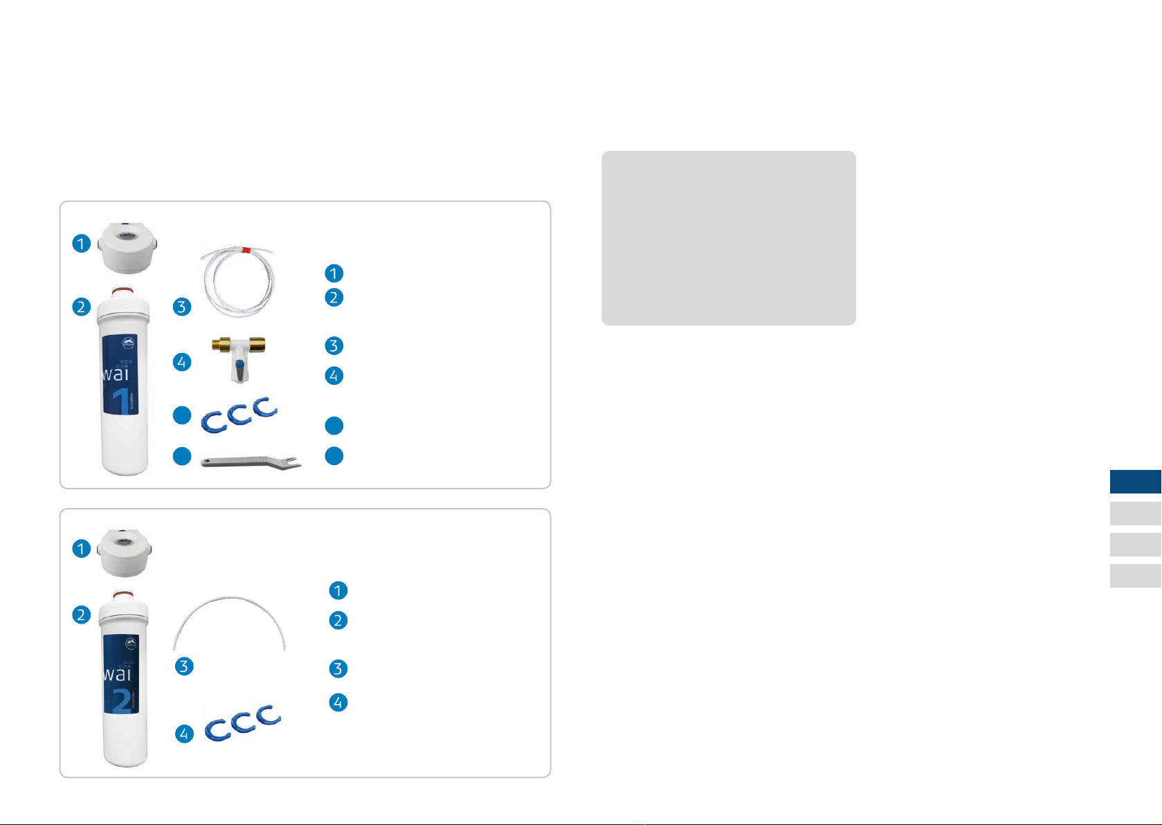
Grundlter
Textiler Grob- und Vorlter z.B. zur
Entfernung von stark partikelbela-
stetem oder verschmutztem (Trü-
bungen) Eingangswasser.
Der Sedimentlter ist mit einem
antibakteriellen Schutz versehen.
Bei Kontakt von Keimen mit der
Schutzoberäche wird deren Ver-
mehrungsprozess unterbrochen.
Intensivlter
Spezial-Aktivkohle-Blocklter
aus Kokosnuss-Aktivkohle.
Reinigt das Wasser von organi-
schen Verunreinigungen, uner-
wünschten Geschmack- und Ge-
ruchsstoen sowie Hormone und
Pestizide.
Kalkschutz
Der Kalklter reduziert die Karbo-
nat-Härte des Wassers. Das Wasser
bleibt chemisch unverändert. Da die
Mineralien im Wasser erhalten blei-
ben, ändert sich der Messwert von
TDS-Geräten unter Umständen nicht.
Der Wasseruss sollte nicht mehr
als ca. 2 l/min. betragen, damit
eine Entkalkung gewährleistet ist.
PI-Filter
Die PI Filterkartusche wurde eigens
für das MAUNAWAI® Wasserlter-
System entwickelt und bietet eine
besonders hohe Qualität. Vorteile:
pH-Wert erhöht sich; Sauersto-
abgabe; antibakterielle Wirkung;
Wasserstabilisierung; feine Cluster-
bildung; gibt Mineralien u. Spuren-
elemente ab (TDS-Wert erhöht sich)
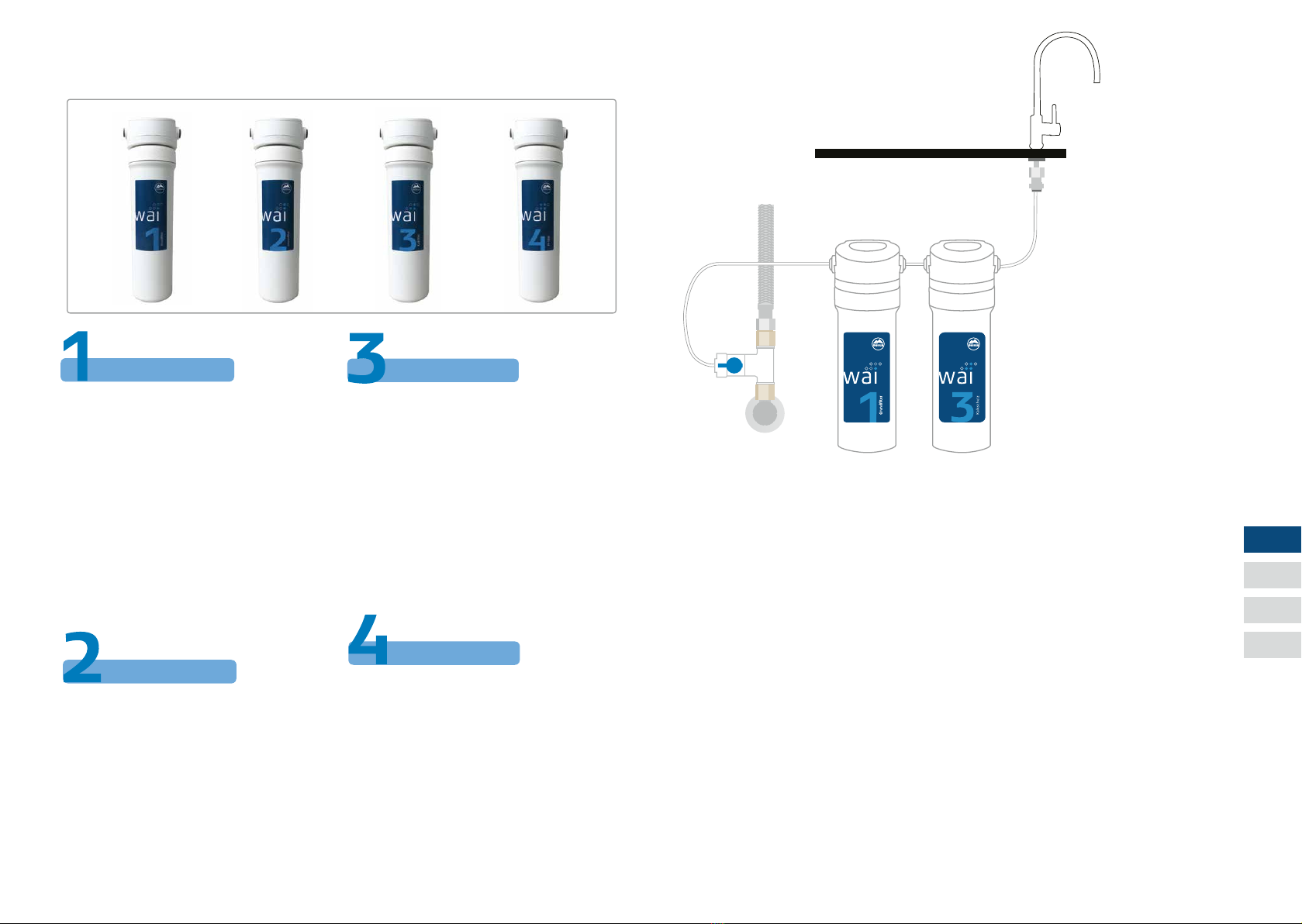
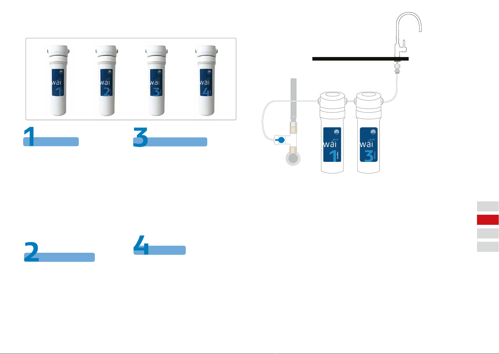
DIE WAI-FILTER Chemiefreier Kalkschutz
Die MAUNAWAI® Kalkschutz-
Kartusche reduziert die Karbo-
nat-Härte in einem besonde-
ren Verfahren, bei dem Kalk in
Kohlenstodioxid umgewandelt
wird.
Im Unterschied zu herkömmlichen
Ionen-Tauschern, die zum Beispiel
Kalk aufnehmen und Natrium ab-
geben, wird Ihr Wasser durch den
MAUNAWAI® Kalkschutz nicht mit
weiteren Feststoen belastet.
Stattdessen wird der gelöste Kalk
in Kohlensäure umgewandelt, wel-
che sich nach dem Austreten aus
dem Hahn verüchtigt.
Auf diese Weise bleiben Minera-
lien dem gelterten Wasser er-
halten.
Der Wasseruss sollte nicht mehr
als ca. 2 l/min. betragen, damit eine
Entkalkung gewährleistet ist.
Die Nutzungsdauer ist vom Härte-
grad des Eingangswassers abhän-
gig.
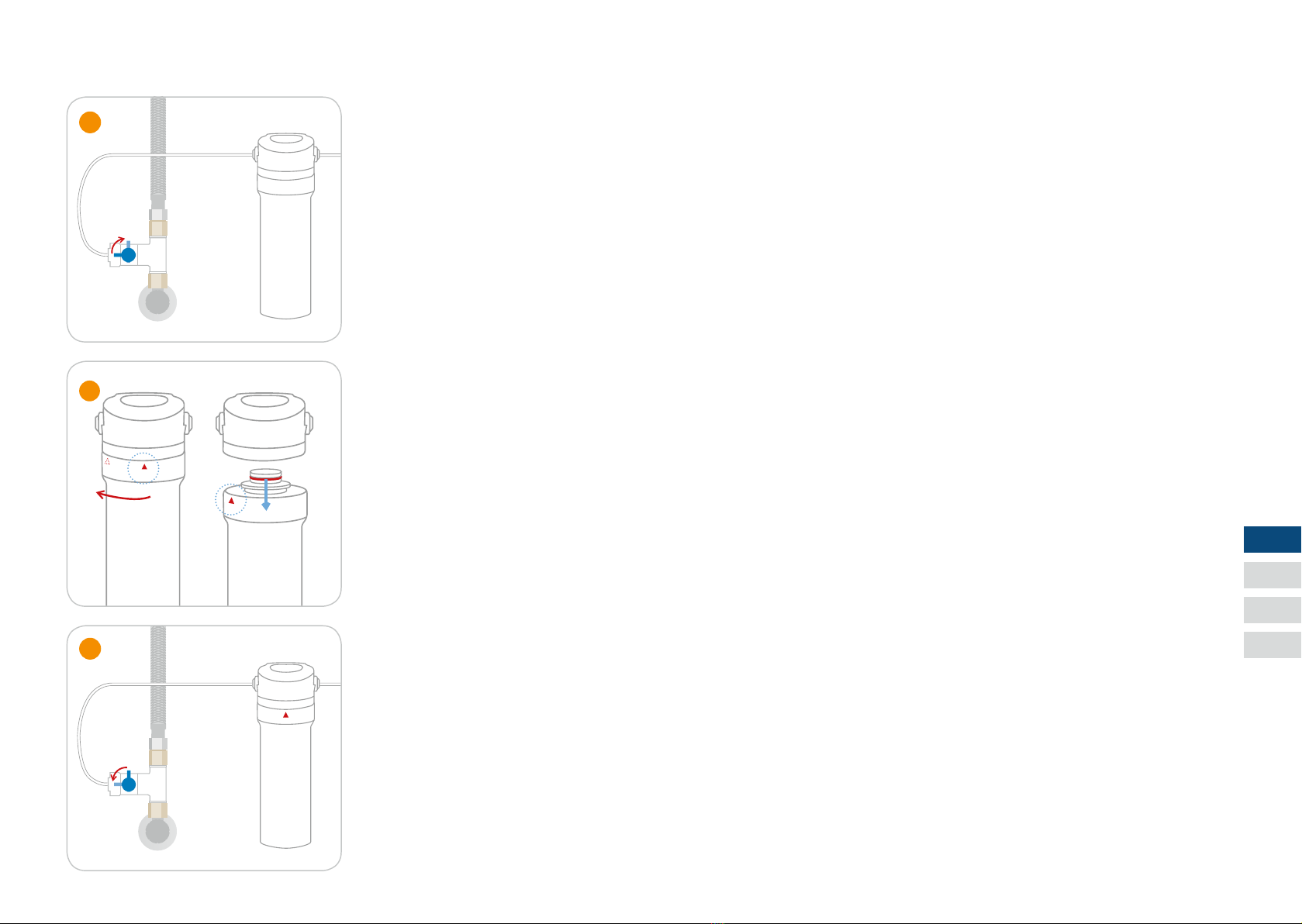
Die Kartusche sollte gewechselt
werden, wenn die kalktypischen
Erscheinungen wieder auftreten.
Bio-Kalkschutz
Grundlter
Intensivlter
Kalkschutz
PI Filter