Maverick 17 HPX-V 2014 User manual

Model year 2014! ! 1
Maverick Boat Company, Inc. • 3207 Industrial 29th St. • Fort Pierce,
Florida 34946 • (772)-465-0631 or (888)-shallow • Fax: (772) 489-2168
MAVERICK 17 HPX-V
Owner’s Manual
Dear New Boat Owner,
Welcome to the Maverick Family!
Thank you for choosing a Maverick boat to transport you to
your angling dreams. We believe the Maverick 17 HPX-V is the
best backcountry boat on the market, and we’re sure that you’ll be
completely satisfied with the unmatched performance, quality and
fishability of your new boat.
We value your input, not just at the time of the sale, but
throughout the entire boat ownership period, and we’ve taken
steps to allow you to share that information. Over the next year or
so, you will receive at least two questionnaires to fill out and
return.
Be sure to visit our website www.maverickboats.com to find
information on company events like our Owner’s Tournaments
and Corporate Calendar. You’ll find a wealth of information on our
Forum, where you can ask questions, get answers and join other
Maverick owners to discuss all applications of your boat. We’re
proud to have you as a member of the Maverick family!
Tight lines and screaming drags!
D. Scott Deal

Model year 2014! ! 2
Maverick Boat Company, Inc. • 3207 Industrial 29th St. • Fort Pierce,
Florida 34946 • (772)-465-0631 or (888)-shallow • Fax: (772) 489-2168
TABLE OF CONTENTS
17 HPX-V SPECIFICATIONS
L.O.A............................................................16’ 09”
BEAM..............................................................6’03”
DRAFT................................................................8”
WEIGHT W/ ENGINE............................1,150 LBS.
FUEL CAPACITY........................................24 GAL.
MAX H.P......................................................90 HP
MAX CAPACITIES........3 PERSONS OR 450 LBS
Maintenance and Cleaning..........................................................3
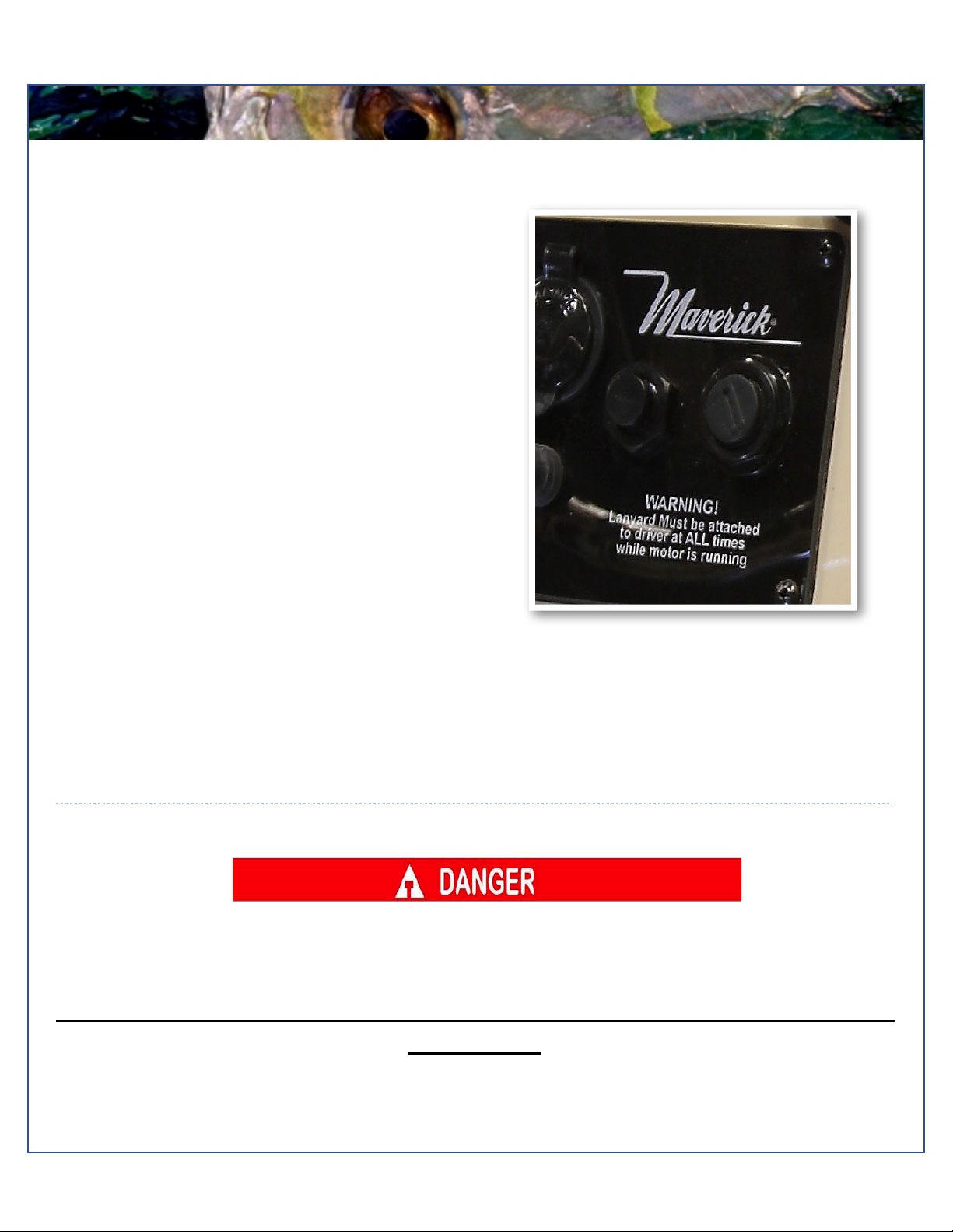
Engine Stop Switch......................................................................4
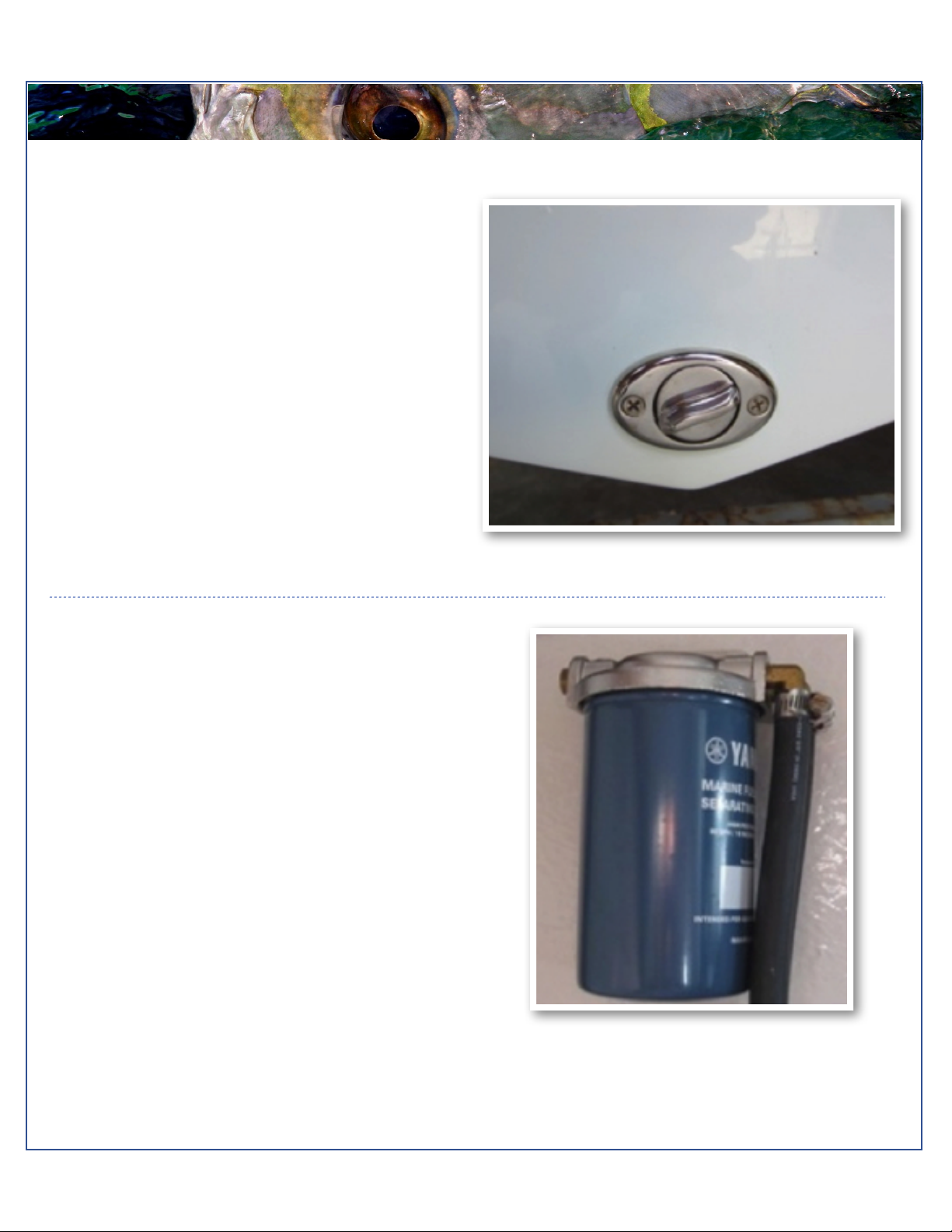
Fuel / Water Separators...............................................................5
Garboard Drain Plug....................................................................5
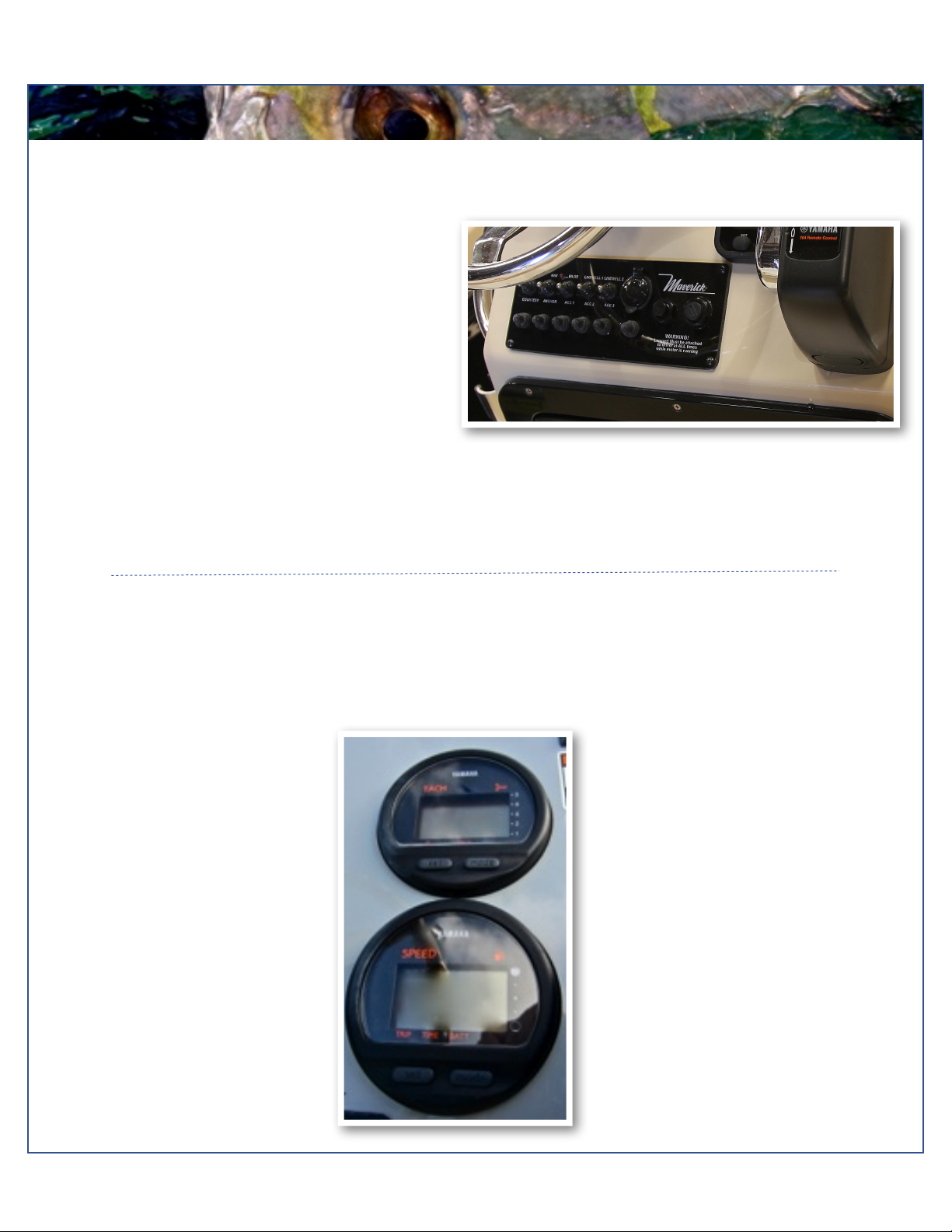
Gauges.........................................................................................6
Switch Panel................................................................................6
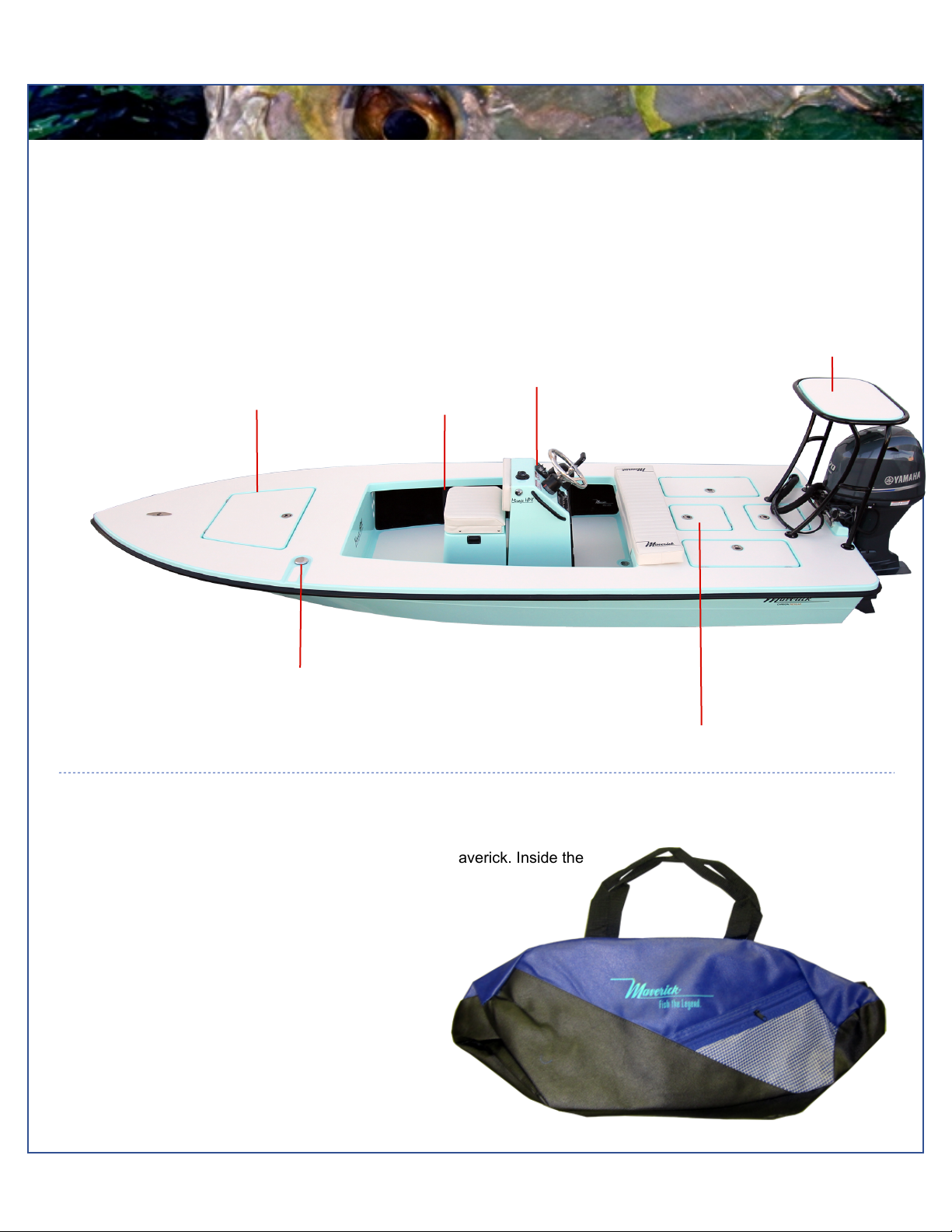
Boat Layout..................................................................................7
Ditty Bag.......................................................................................7
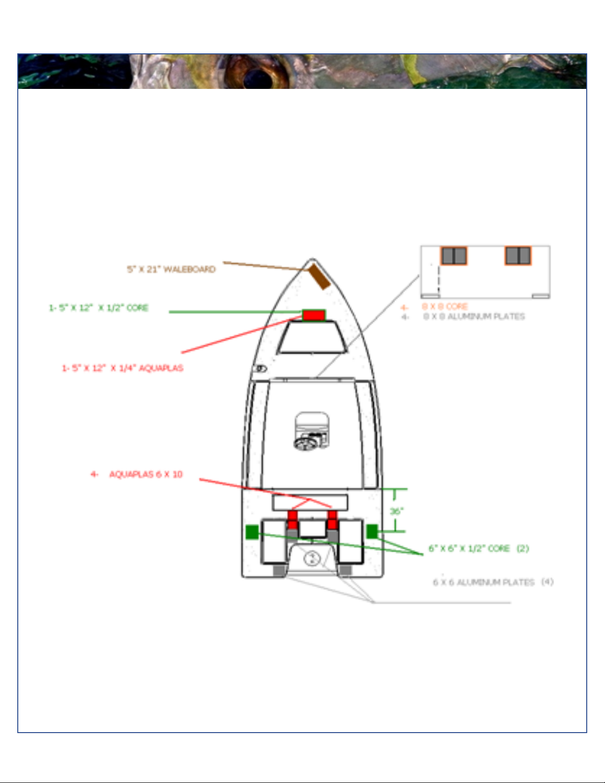
Aluminum Plate Locations............................................................8
Trolling Motor/Wiring System.......................................................9
Bilge System..............................................................................11
Props..........................................................................................12
Fuel System...............................................................................13
Self Bailing Cockpit....................................................................14
Livewell System.........................................................................14
Wiring System/Breakers and Fuses...........................................15
Battery Switch/Breaker Panel....................................................16
Gauge Upgrades........................................................................17
Saltwater Washdown.................................................................17
Optional Trim Tabs.....................................................................18
Optional Power Pole..................................................................19
Power Pole Aluminum Plate Locations......................................19
Optional Boarding Ladder..........................................................20
Optional Jackplate......................................................................20
Warranty.....................................................................................21

Model year 2014! ! 3
Maverick Boat Company, Inc. • 3207 Industrial 29th St. • Fort Pierce,
Florida 34946 • (772)-465-0631 or (888)-shallow • Fax: (772) 489-2168
MAINTENANCE & CLEANING
Maintenance
Maverick Boats advises owners that maintenance and repairs should be performed at an authorized Maverick dealer. The
following information is general in nature and should not be considered a repair manual or guidelines set forth by Maverick
Boat Company.
Cleaning
Each Maverick boat is constructed using the finest materials and components available. However, no material is immune to
the ravages of the saltwater environment. After each use, your boat should be rinsed thoroughly with fresh water. A mild
detergent may also be used to remove any dirt, silt or stains. A light coat of lubricant on metal railing, screws and electrical
connections will help prevent electrolysis. The same holds true for your trailer.

Model year 2014! ! 4
Maverick Boat Company, Inc. • 3207 Industrial 29th St. • Fort Pierce,
Florida 34946 • (772)-465-0631 or (888)-shallow • Fax: (772) 489-2168
ENGINE BREAK-IN
Ignition (above)
Engine Break-In Period
New engines require a period of break-in to allow the
surfaces of the moving parts to mate evenly. Different
engines require different break-in periods and methods.
For instructions on break in methods, refer to your
Yamaha Engine Owner’s Manual for the correct break-in
procedures and times for your model engines
Engine Stop Switch
If activated, the spring loaded engine stop switch will
automatically shut down the engine during emergency
situations to prevent uncontrolled or unattended
operation. Certain emergency conditions (e.g., turbulent
water, wakes, unanticipated movement) may impair a
person’s ability to operate the craft safely. The switch,
located on the helm, must have the safety lanyard
attached at its base. This activates the protective
shutdown circuitry.
Securely attach the other end of the lanyard to the
operator of the boat. If the operator moves, falls or is at
an unsafe distance from the steering wheel, tension on
the lanyard will pull it from the switch. When the lanyard is
removed, the engine stop switch is released and
automatic engine shutdown occurs.
Engine Stop Switch
An engine stop switch system that is not used or does not function properly can cause death or serious injury.
DO NOT operate the boat if the engine stop switch system does not function properly. Go to a Maverick Dealer to
have this resolved immediately
The lanyard should be securely attached to the boat operator at all times that the
engine is on.

Model year 2014! ! 5
Maverick Boat Company, Inc. • 3207 Industrial 29th St. • Fort Pierce,
Florida 34946 • (772)-465-0631 or (888)-shallow • Fax: (772) 489-2168
FUEL-WATER SEPARATOR & DRAIN
Fuel/Water Separator (above)
Fuel-Water Separator
Each boat is equipped with a fuel water separator to
ensure maximum performance and protect the outboard
engine from contaminated gasoline. The fuel separator
is a metal, cylindrical unit that can be accessed through
the aft bilge compartment.
The fuel separator can be checked by removing it from
the mounting bracket and dumping it into an approved
waste collection device. If there appears to be an
excessive amount of water, the filter component should
be changed. See your authorized Maverick dealer for
replacement parts.
Maintenance Note
In addition, the fuel separator should be changed as part of routine maintenance at 20, 50 and 100 hour checks.
Garboard Drain Plug
The garboard drain plug is the small metal plug located at
the lowest point on the hull, at the bottom of the transom
right above the keel. The drain has been designed so that
it can be loosened by hand while the hull is out of the
water for draining. This allows the plug to stay in contact
with the surrounding frame so you’ll never misplace or
lose it. You can completely remove the insert by pulling
back and continue turning in a counter clockwise motion.
It is manufactured with a rubber seal in place to ensure
you bilge is watertight. Always make sure before putting
the boat in the water that this plug is hand tightened
firmly. Excess water in the bilge may be an indication of a
problem with this plug or the automatic bilge pump. Refer
to page 10 of this Owner’s Manual for information on your
boats bilge system.

Model year 2014! ! 6
Maverick Boat Company, Inc. • 3207 Industrial 29th St. • Fort Pierce,
Florida 34946 • (772)-465-0631 or (888)-shallow • Fax: (772) 489-2168
SWITCH AND INSTRUMENTS
Gauges
The standard digital gauges include a Yamaha tachometer and a Yamaha speedometer. The tachometer has several built
in features including an engine temperature monitor, oil level monitor and engine trim indicator. The speedometer includes
a digital readout of the speed, an hour meter, trip meter and clock. For more information on the specifics of your Yamaha
gauges, see your Yamaha owner's manual.
Switch Panel
The dual activation switches are set in a standard grid.
These switches can be flipped either up or down to
control different accessories. The accessories located
directly above a switch are activated when the switch is
in the “Up” position and the accessories located directly
below the switch are activated when the switch is flipped
into the “Down” position. For example, in the “Up”
position the second switch to the left will turn on the
navigation lights, but if in the “Down” position it will turn
on the anchor light. The bilge switch is an on-demand
switch to run your bilge pump and is used as a backup in
case the float indicator in your bilge pump becomes
clogged. Switch Panel

Model year 2014! ! 7
Maverick Boat Company, Inc. • 3207 Industrial 29th St. • Fort Pierce,
Florida 34946 • (772)-465-0631 or (888)-shallow • Fax: (772) 489-2168
BOAT LAYOUT
DITTY BAG
You should have received a cloth ditty bag with your new Maverick. Inside the
ditty bag are the following items:
1 Large Livewell Standpipe
1 Small Livewell Standpipe
1 1-1/2”Livewell Pacifier Plug with Ring
2 ignition keys and Emergency Kill Cord
1 Engine Start Cord
1 1” Twist Tie Drain Plug
1 Gas Fill Key
3 Bungees for push pole holder
3 Push Pole Holders
Various Product Manuals
Mirage 17 HPX-V Boat Layout
Your Maverick is designed to create the maximum amount of storage capacity without affecting fishing ability. Livewells,
gasketed and guttered storage compartments and lockers are built to protect your gear from the elements.
Become familiar with the boat layout and features to take advantage of their special qualities. All Maverick boats are
designed by anglers, for anglers, to offer the best fishing features in the Bay Boat market. The Maverick superior layout
offers hands-free fishability with the most storage and casting room available.
Poling Tower
Fuel Fill
Forward Storage
Gunnel Rod
Holders
Livewell
Console

Model year 2014! ! 8
Maverick Boat Company, Inc. • 3207 Industrial 29th St. • Fort Pierce,
Florida 34946 • (772)-465-0631 or (888)-shallow • Fax: (772) 489-2168
BACKING PLATES
Backing Plates
The diagram below shows all the screw-retention backing plates originally placed in the deck of a 17 HPX-V during the
construction process.

Model year 2014! ! 9
Maverick Boat Company, Inc. • 3207 Industrial 29th St. • Fort Pierce,
Florida 34946 • (772)-465-0631 or (888)-shallow • Fax: (772) 489-2168
TROLLING MOTOR WIRING SYSTEM
Trolling Motor Wiring System
Your Maverick 17 HPX-V comes standard with a 24V trolling motor wiring system. A trolling motor mounting plate was built
into the bow of your Maverick during the manufacturing process. To attach a trolling motor, please go to your nearest
Maverick dealer. All trolling motors should be attached by drilling through the mounting plate with a 13/64” drill bit and 1/4”
tap and using 1/4” #20 machine screws. The plate is designed to accommodate the mounting patterns of all trolling motor
brands on the market currently. See below for optional trolling motor system with battery charger and wire routing.

Model year 2014! ! 10
Maverick Boat Company, Inc. • 3207 Industrial 29th St. • Fort Pierce,
Florida 34946 • (772)-465-0631 or (888)-shallow • Fax: (772) 489-2168
BALL VALVES AND LIVEWELL PUMP
THE LIVEWELL PUMP
ASSEMBLY IN THE “OPEN
POSITION
Ball Valves
Ball valves can be used to serve several purposes. They
allow seawater to enter the boat, in the case of livewells,
and they also act as a safeguard to stop water from
entering in case of part failure, and function as an
emergency shutoff. To tell which position a ball valve is in,
open or closed, look at the valve and determine the
direction of flow. When the ball valve handle is in the
same position as the direction of flow, the valve is in the
“OPEN” position. When the ball valve handle appears to
cross the direction of flow, the valve is in the “CLOSED”
position.
Mirage Livewell Pump Assembly
The livewell pump assembly is composed of a scoop
strainer mounted to the bottom of the hull, a thru hull
fitting, ball valve assembly, and the pump. As you can
see, the ball valve assembly is in the “OPEN” position.
This is the correct position for the operation of the livewell
system.
Water Flow
CLOSED

Model year 2014! ! 11
Maverick Boat Company, Inc. • 3207 Industrial 29th St. • Fort Pierce,
Florida 34946 • (772)-465-0631 or (888)-shallow • Fax: (772) 489-2168
BILGE
Bilge
The bilge of your 17 HPX-V Mirage should always be checked after launch. A small amount of water in the bilge is normal
for this area of the boat. Large amounts of water or any signs of fuel or oil require immediate attention. Never pump fuel or
oil overboard while your boat is in the water.
Large quantities of water in the bilge may be an indication of a leak or that your bilge pump is jammed, broken or has blown
a 6 amp fuse. First check that your bilge pump is running. Turn the switch on and listen for the bilge pump to turn on. If the
bilge pump does not come on, check your fuse box to make sure the pump hasn’t blown a fuse. If the fuse is damaged,
replace it and turn the switch on again, listening for the bilge pump to come on.
If the bilge pump is working and pumping water, but the water level in the bilge does not go down, you likely have a leak
which requires immediate attention. Remove your boat from the water and see your local Maverick dealer to have the
bilge area inspected for possible leaks.
Fuel leaks also require immediate attention. Be sure to check for fuel leaks frequently and repair any problems
immediately. Any replacement of parts or repairs to the fuel system should be performed by a trained marine mechanic.
See your authorized Maverick dealer for parts and repair.
Use bilge cleaner products to remove any obvious stains. Consult your authorized Maverick dealer for recommended
types of bilge cleaners.
The Bilge Pump is Mounted to ABS Plastic
If the fuse is in working order, make sure the pump is turned off, then remove pump housing from the mounting base by
pressing in tabs on the sides. The entire bilge pump and wiring should release from the cradle. Check the underside and
impeller areas for miscellaneous items that might clog the pump.
Items such as monofilament, plastic, rocks and small clumps of debris can easily clog the impeller and prevent the bilge
pump from operating correctly. Should you find a clog, remove the item and turn the pump switch to the “on” position. If
the pump runs, turn the switch “off” and return the pump to its cradle.
If the fuse is working and the impeller is not clogged, the bilge pump is probably bad and needs to be replaced. See your
local Maverick dealer for bilge pump replacement.

Model year 2014! ! 12
Maverick Boat Company, Inc. • 3207 Industrial 29th St. • Fort Pierce,
Florida 34946 • (772)-465-0631 or (888)-shallow • Fax: (772) 489-2168
PROPS
Props
Prop selection on your Mirage is determined by your local Maverick dealer but based on recommendations made by
Maverick Boat Company and Yamaha Marine to give your boat the maximum overall performance. Different prop designs
may improve performance or can be tailored to enhance specifics of boat and motor performance.
For instance, a prop with a smaller pitch will increase speed out of the hole (jumping onto plane) but will produce a
decreased overall speed compared to a prop with a larger pitch. Four bladed props may increase overall speed or allow
the boat to run shallower, and some props can decrease cavitation at high speeds. Your individual prop needs will
determine the prop design and size that best fits your performance requirements.
Always inspect the engine and prop prior to launching your boat. Key prop issues include tangled fishing line or other
types of debris, cracked blades or fluid leaking out of the seal. Look for fishing line tangled around the prop or lower unit
seal while the engine is off . Consult your Yamaha Owner’s Manual to address these issues.

Model year 2014! ! 13
Maverick Boat Company, Inc. • 3207 Industrial 29th St. • Fort Pierce,
Florida 34946 • (772)-465-0631 or (888)-shallow • Fax: (772) 489-2168
FUEL SYSTEM
FUEL SYSTEM DIAGRAM
FUEL SYSTEM
Your Mirage comes with a 24 gallon aluminum fuel cell
stationed just aft of the forward casting deck hatch. The
fuel fill receptacle is on the port gunwale forward of the
console. There's also a recessed fuel overflow vent on
the port side of the boat just below the fuel receptacle.
We regularly pressure test each fuel system when it is
initially received at the factory and when it leaves the
factory as a component on a new boat. Should you
experience any fuel related problems or suspect
problems with the fuel system, immediately take your
boat to your local Maverick dealer.
CAUTION—Do not smoke while filling the tank. Be sure to turn off the engines and all electrical
equipment when fueling the boat to prevent accidental discharges of static electricity. Use only
the recommended gasoline (see Yamaha’s Owner’s Manual). Do not use fuels with alcohol or
alcohol related derivatives that can cause marine fuel system hoses to deteriorate.

Model year 2014! ! 14
Maverick Boat Company, Inc. • 3207 Industrial 29th St. • Fort Pierce,
Florida 34946 • (772)-465-0631 or (888)-shallow • Fax: (772) 489-2168
LIVEWELL SYSTEM
Livewell System
The new and improved 18 gallon livewell system on the 17 HPX-V keeps bait alive longer than any other system on the market. It
comes standard with a duel in-flow system and a bottom to top drain system. The inflow system and a unique drain system
prevents dead zones and quickly expels any harmful chemicals (such as ammonia) from the water. To efficiently operate your
livewell, the following steps should be taken:
1. Open livewell hatch.
2. Remove acrylic grate by turning tabs and pulling out.
3. Install stand-up pipe snugly.
4. Ensure livewell pump ball valve is in open position.
5. Replace grate making sure that the larger holes are
on the bottom. Reposition holding tabs to secure
grate.
6. Turn on livewell switch.
Your HPX-V comes with two standpipes and a pacifier-style drain
plug to control water levels inside the livewell. The smaller
standpipe is for use with crustaceans like shrimp and crabs that
prefer a lower water level. The taller standpipe is for baitfish, and
the drain plug is to hold water or seal the compartment. The
standpipes should be placed in the hole located in the floor of the
livewell and fit snugly. On rare occasions, the livewell will not pump water even though the switch is turned on, the system is open
and the livewell pump is running. If that occurs, shift the throttle into reverse and back the boat several feet to purge a possible air
pocket in the system. If there appears to be a clog in the drain, remove the grate and clear the top of the standpipe of any detritus.
Your boat might come with an optional recirculation system. This is a closed system that recycles the water already within the well.
This system is also controlled by a switch on the switch pannel and allows the boat operator to operate the livewell without an
outside feed. This is ideal if you are transporting bait from different water extremes.
*--NOTE--Be sure to turn the shut-off valve to the 90-degree off position BEFORE unscrewing the filter cap (see
photo above). Failure to do so will result in outside water entering the bilge area.

Model year 2014! ! 15
Maverick Boat Company, Inc. • 3207 Industrial 29th St. • Fort Pierce,
Florida 34946 • (772)-465-0631 or (888)-shallow • Fax: (772) 489-2168
ROD AND POLE STORAGE
Rod Lockers
The 17 HPX-V center console model comes standard with under
gunnel rod racks on both the port and starboard sides. These give
you space to safely store 6 rods for your fishing needs. LED
lighting under the gunwales help illuminate the area.
Push Pole Storage
Push pole holders come standard with your Maverick 17 HPX-V
and are located in your ditty bag. We advise that your Maverick
dealer fit them to your particular push pole. This diagram
shows where material has been added to the deck to insure the
holders stay well fastened for the life of your boat.
Push Pole Holder Mounts

Model year 2014! ! 16
Maverick Boat Company, Inc. • 3207 Industrial 29th St. • Fort Pierce,
Florida 34946 • (772)-465-0631 or (888)-shallow • Fax: (772) 489-2168
WIRING
!"#$%&'()!"&*)+"%*$,,)
-.)/.*,.0$
1&*)2)) ) 34*'5.*)) ) ) ) 6&%$)/.0.%) ) ) 768
9:) ;"#)<=,)>?*,=%4@$*="5.*A) ) ) 8%$B) ) ))9C
D:) ;"#)<=,)) ) ) ) ) 8%$B) )))9C
E:) 7*')<=)>/.*,.0$A)) ) ))))))) ))))))))8%$BF6G&=$)) ))))))))))9C ) ) )))))))
H:) 7*')<=)>-I-J1A) ) ) ))8%$BF6G&=$) ) ) 9C)) 1&*)/)-I-.K)L$'$K=
M:) +.%*) ) ) ) ) ) J%"*N$F6G&=$) ) )))))))))))))))9C
C:) OK%$"P$%)<=) ) ) ) ) Q04$FQ0"'() ) ) 9C)) 1&*)7)-I-.K)L$'$K=
R:) J#$%G$"P)<=,) ) ) ) ) Q04$F8%$$*) ))9C))1&*)Q)-I-.K)L$'$K=
S:) 17;T<)8LJU;V)) ) ) )))))))))))))))Q0"'() ) ) ) 9C)) /.*,.0$)8%.4*P)Q4,
-.)7''$,,.%&$,)) ) ) ) ) ) !"&*)+"%*$,,
1&*)2)) ) 34*'5.*) ) ) ) 6&%$)/.0.%) ) ) 768
9:)) ) Q&0N$) ) ) ) ) Q%.W*) ) )
)9H))))
D:) ) <F6I9 ) ) ) ) ) Q%.W*F6G&=$) ) ) 9H
E:)) ) LT/?L/I9) ) ) ) L$PF6G&=$) ) ) 9H
H:)) ) <F6ID ) ) ) ) ) Q%.W*FX$00.W)))9H
M:)) ) LT<T7OT)6T<<) ) ))Q%.W*FJ%"*N$) ))9H
C:)) ) LT/?L/ID) ) ) ) L$PFX$00. W ) ))9H
R:)) ) QUQQ<TL) ) ) ) L$PFJ%"*N$) ))9H
S:) ) O7<-)67-TL) ) ) ) Q%.W*F8%$$*) ))9H
Y:) ) 3LTO+)67-TL) ) ) ) Q%.W*FQ0"'() ) ) 9H
9Z:)) ) <?[T6T<<)<-O) ) ) ) Q04$F6G&=$) ) ) 9C
99:)) ) /J/\1?-)<-O) ) ) ) Q04$FL$P)) ) 9C
9D:)) ) /J!17L-!T;-)<-O) ) ) Q04$FQ0"'() ) ) 9C
S)1?;)104N
1&*)2)) ) 34*'5.*
9)7//I9
D)7//ID
E)7//IE
H)7//IH
M)7//IM
Wiring
A wiring diagram of your Maverick 17 HPX-V has been included to help troubleshoot any electrical problems or add
additional electronics or electrical connections. We recommend you use a trained marine electrician for all electrical issues.
Inside the console on the starboard side is the ground terminal and the breaker pannel is located in the glove box. All the
grounds lead to the ground terminal and then to the battery via a large diameter black wire.
Always use the recommended breaker/fuse amp sizes. Oversizing or using larger breakers/fuses than required can lead to
electrical shorting and possible damage or destruction of the entire electrical system.
There are open slots on both the ground block and the breaker panel for additional electrical hook-ups. The accessory
switches should be used for any additional hook-ups to protect the entire electrical system. All additional electrical hook-ups
should be performed by a qualified marine electrician.
As a standard practice, we run pull cords forward and aft for any additional wiring needs. For your convenience and ease we
have included a nylon rigging string that runs through the rigging tubes and terminates in the bow. The nylon string will allow
you to easily run any additional wiring through the rigging tubes, thus protecting them from outside elements. We also run a
string aft to the rigging box.
4
3
2
1
8
7
6
5

Model year 2014! ! 17
Maverick Boat Company, Inc. • 3207 Industrial 29th St. • Fort Pierce,
Florida 34946 • (772)-465-0631 or (888)-shallow • Fax: (772) 489-2168
BATTERY SWITCH/MAIN BREAKER
Battery Switch, Shown in the “Off” Position
Battery Switch and Breaker Panel
The battery switch for the HPX-V is located inside the console mounted on the starboard wall. Power from the battery to the
battery switch is protected with a 30 amp inline fuse.
On a single battery system, the battery is wired to the number 1 side of the switch. When additional batteries are on board,
for instance for a trolling motor, one of the batteries should be connected to switch number 2, thereby allowing that battery to
help crank the engine in the event the main battery (switch 1) does not provide ample power. The operator can choose which
battery to utilize by the selection on the switch. The only time the switch should be in the “1 & 2” position is if one battery will
not start the engine. Then, switch to “1 & 2” and have two batteries to start the engine. Once the engine is started turn the
switch back to the number one battery so that the engine alternator is once again charging that battery.

Model year 2014! ! 18
Maverick Boat Company, Inc. • 3207 Industrial 29th St. • Fort Pierce,
Florida 34946 • (772)-465-0631 or (888)-shallow • Fax: (772) 489-2168
TRIM TABS
Trim Tab
Trim Tabs
Trim Tabs are standard on your new Maverick. Integrated electric trim tabs can enhance the performance of your boat.
The tabs are electric and therefore do not require a trim tab pump. By not having a pump there is no possibility of fluid
leaks from a pump.
Trim tabs allow for maximum boat performance, and are great for balancing weight in the boat. They also allow the
boat operator to lift or lower the hull to accommodate for different running situations.
For the operation of trim tabs, note that the port trim tab switch will affect the port side of the boat and the starboard
switch will affect the starboard side. To lower a particular side, press the top of the corresponding switch down.
Pressing the top of both switches down will lower the bow evenly. To raise the bow, press the bottom of the
corresponding switch.

Model year 2014! ! 19
Maverick Boat Company, Inc. • 3207 Industrial 29th St. • Fort Pierce,
Florida 34946 • (772)-465-0631 or (888)-shallow • Fax: (772) 489-2168
AFT CUSHION
Aft Cushion
The 17 HPX-V comes with an aft cushion. The cushion bottom is removable and is held in place by several sets of stainless
steel snaps. To remove the cushion, simply turn the tabs so that they align with the holes in the cushion and remove and store
the cushion. When left outside or exposed to the elements for a prolonged period of time, it is recommended to take off the
seat cushions and store them in a dry place. In addition, it is recommended to remove this cushion when trailering for
prolonged periods or at high speeds.

Model year 2014! ! 20
Maverick Boat Company, Inc. • 3207 Industrial 29th St. • Fort Pierce,
Florida 34946 • (772)-465-0631 or (888)-shallow • Fax: (772) 489-2168
OPTIONAL FEATURES
Command Link Gauges
Command Link gauges are an option for the 17 HPX-V and are an upgrade from the standard digital gauges. Command Link
gauges allow access to more information. Displays are user-selectable so you can choose the functions displayed on each
gauge and what order. Speed data can be displayed from a pitot tube, Triducer, or NMEA protocol GPS unit
Table of contents
Other Maverick Boat manuals
Popular Boat manuals by other brands

PURSUIT
PURSUIT 2670 Denali owner's manual

Walker Bay
Walker Bay AIRIS 16425 PLAY 8 Owners & safety manual

Dufour Yachts
Dufour Yachts 365 Grand Large owner's manual

EuroGames
EuroGames BUMPER BOAT Series Operation and Maintenance Handbook

PURSUIT
PURSUIT C 300 owner's manual

Pakboats
Pakboats Puffin II Assembly and User Information