Maverick 18 HPX-V User manual

1
Maverick Boat Group
3207 Industrial 29th St. • Fort Pierce, Florida 34946
(772)-465-0631 •Maverickboats.com
18 HPX-V Owner’s
Manual
Model Year 2024

2
Maverick Boat Group
3207 Industrial 29th St. • Fort Pierce, Florida 34946
(772)-465-0631 • Maverickboats.com
Table of Contents
18 HPX-V Specifications.........................................................................................................................3
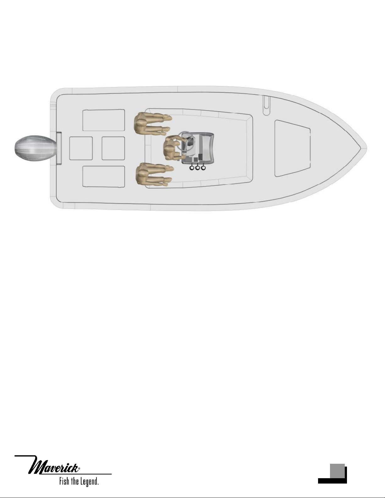
Designated Occupency Positions ......................................................................................................4
Pre-Operation Checklist ........................................................................................................................5
Maintenance & Cleaning ......................................................................................................................6
Engine Break-In Period...........................................................................................................................8
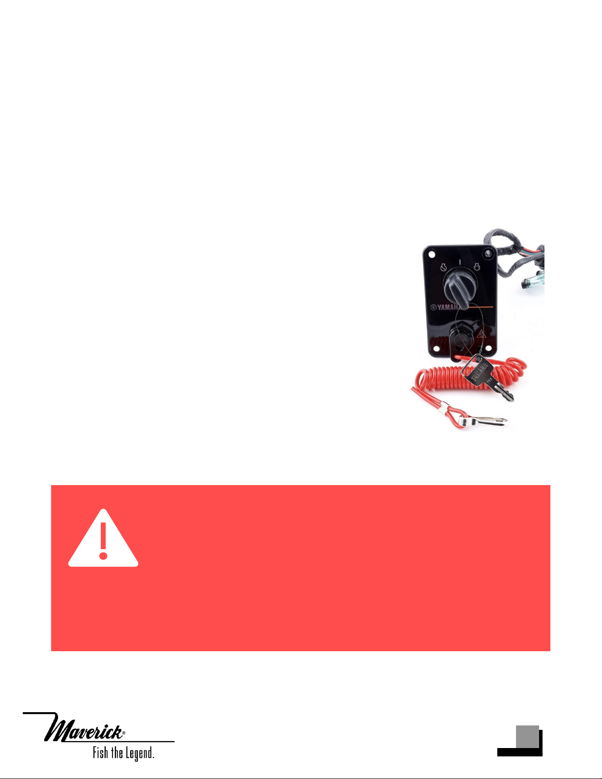
Switch Panel & Helm ...............................................................................................................................9
Fuel-Water Separator & Drain.............................................................................................................11
Bilge ...........................................................................................................................................................12
Systems .....................................................................................................................................................13
Trolling Motor Wiring..............................................................................................................................14
Battery Switch and Breaker Panel.....................................................................................................14
Ladder & Props........................................................................................................................................15
Unassisted Reboarding.........................................................................................................................15
Fuel System..............................................................................................................................................16
Self-Bailing Cockpit & Livewell...........................................................................................................16
Wiring.........................................................................................................................................................19
Standard Features..................................................................................................................................20
Optional Features ..................................................................................................................................22
Location and Reordering of Warning Labels..................................................................................23
Location and Reordering of Warning Labels..................................................................................24
18 HPX-V Optional Trolling Motor with Battery Charger and Wire Routing............................25
Upholstery Care & Cleaning Guide ..................................................................................................26
Warranty ...................................................................................................................................................27

3
Maverick Boat Group
3207 Industrial 29th St. • Fort Pierce, Florida 34946
(772)-465-0631 • Maverickboats.com
18 HPX-V Specifications
L.O.A.......................................................................................................................18’ 04”
BEAM......................................................................………………….…....................6’08”
DRAFT.............................................................................................................................9”
DEADRISE………………………………………………………………………………13 DEG.
WEIGHT W/ ENGINE..........................................................................................1,460 LBS.
FUEL CAPACITY....................................................................................................29 GAL.
MAXIMUM H.P.............................................................................................................150
Battery Switch /
Battery Access
Release well
Fuel Fill
Bilge Access
Dry Storage
Livewell
Dry Storage

4
Maverick Boat Group
3207 Industrial 29th St. • Fort Pierce, Florida 34946
(772)-465-0631 • Maverickboats.com
Designated Occupency Positions

5
Maverick Boat Group
3207 Industrial 29th St. • Fort Pierce, Florida 34946
(772)-465-0631 • Maverickboats.com
Pre-Operation Checklist
We recommend you print this document and store it at the helm station.

6
Maverick Boat Group
3207 Industrial 29th St. • Fort Pierce, Florida 34946
(772)-465-0631 • Maverickboats.com
Maintenance & Cleaning
Maintenance
Maverick advises owners that maintenance and repairs should be performed at an
authorized Maverick Dealer. The following information is general in nature and should
not be considered a repair manual or guidelines set forth by Maverick Boat Group.
Cleaning
Each Maverick boat is constructed using the finest materials and components available.
However, no material is immune to the ravages of the saltwater environment. After each
use, your boat should be thoroughly washed using fresh water. To avoid water spots, dry
your vessel using a soft cloth. A fiberglass wax may be used to preserve the luster of the
hull.
Thorough and routine cleanings of your stainless fittings are required to maintain their
appearance. After each use of your boat, clean stainless fittings using fresh water and a
mild soap. Dry fittings completely. A wax or polish may be applied after cleaning. Any
rust must be removed as soon as possible to prevent irreversible damage to your vessel
and/or its components. A light coat of lubricant on metal railing, screws and electrical
connections will help prevent electrolysis. The same holds true for your trailer.

7
Maverick Boat Group
3207 Industrial 29th St. • Fort Pierce, Florida 34946
(772)-465-0631 • Maverickboats.com

8
Maverick Boat Group
3207 Industrial 29th St. • Fort Pierce, Florida 34946
(772)-465-0631 • Maverickboats.com
Engine Break-In Period
New engines require a period of break-in to allow the surfaces of the moving parts to
mate evenly. Different engines require different break-in periods and methods. For
instructions on break-in methods, refer to your Yamaha Engine Owner’s Manual for the
correct break-in procedures and times for your model engines.
Engine Stop Switch
If activated, the spring-loaded engine stop switch will
automatically shut down the engine during emergency
situations to prevent uncontrolled or unattended operation.
Certain emergency conditions (e.g., turbulent water, wakes,
unanticipated movement) may impair a person’s ability to
operate the craft safely. The switch, located on the helm, must
have the safety lanyard attached at its base. This activates the
protective shutdown circuitry.
Securely attach the other end of the lanyard to the operator of
the boat. If the operator moves, falls or is at an unsafe distance
from the steering wheel, tension on the lanyard will pull it
from the switch. When the lanyard is removed, the engine stop
switch is released and automatic engine shutdown occurs.
Engine Stop Switch
DANGER:
An engine stop switch system that is not used or does not function
properly can cause death or serious injury. DO NOT operate the boat if
the engine stop switch system does not function properly. Go to a
Maverick Dealer to have this resolved immediately.
The lanyard should be securely attached to the boat operator at all times that
the engine is on.

9
Maverick Boat Group
3207 Industrial 29th St. • Fort Pierce, Florida 34946
(772)-465-0631 • Maverickboats.com
Switch Panel & Helm
Switch Panel & Helm
At the helm of your Maverick, you have a main
switch panel, which is located below the steering
wheel. This panel controls your lights, horn,
accessories, livewell, and your bilge. The bilge
switch is an on-demand switch to run your bilge
pump and is used as a backup in case the float
indicator in your bilge pump becomes clogged.
To the right of the steering wheel, you have your
two trim tab switches, which are standard on the
18 HPX-V. The boat also comes standard with a
compass mounted on top of the console.
Gauges
The instrument panel on your Maverick is composed of one Yamaha digital gauge and a
series of dual activation switches. The switches come with accessory plug-ins for wiring
additional electronics, pumps, or electrical circuits.
The standard digital gauge includes a Yamaha tachometer and a Yamaha speedometer
on one screen. The tachometer has several built-in features including an engine
temperature monitor, oil level monitor and engine trim indicator. The speedometer
includes a digital readout of the speed, an hour meter, trip meter and clock. For more
information on the specifics of your Yamaha gauges, see your Yamaha owner's manual.
Helm & Switch Panel

10
Maverick Boat Group
3207 Industrial 29th St. • Fort Pierce, Florida 34946
(772)-465-0631 • Maverickboats.com
Navigation Lights
Your Maverick 18 HPX-V is equipped with port and starboard navigation lights and an
anchor light. Navigation and anchor lights should not be modified, and additional lights
should not be added such that they diminish the visibility of navigation lights or could
be confused with navigation lights. Both navigation and anchor lights come labeled with
an expiration year in which the lights need to be replaced by. Reach out to your local
dealer or the manufacturer to replace lights.
oNavigation Lights
oPart number: 43028600 (Port), 43028700 (Starboard)
oExpiration Year: 2043
oAnchor Light
oPart number: 43013002 standard
oExpiration Year: 2043
Maverick Duffel Bag
Along with your boat, you received a Duffel Bag with your new Maverick. Inside the
Duffel Bag are the following items:
o1 Large Livewell Standpipe
o1 Small Livewell Standpipe
o1 1-1/2” Livewell Pacifier Plug with Ring
o2 ignition keys and Emergency Kill Cord
o1 Engine Start Cord
o1 1” Twist Tie Drain Plug
o1 Gas Fill Key
o3 Bungees for push pole holder
o3 Push Pole Holders
oVarious Product Manuals

11
Maverick Boat Group
3207 Industrial 29th St. • Fort Pierce, Florida 34946
(772)-465-0631 • Maverickboats.com
Fuel-Water Separator & Drain
Fuel-Water Separator
Each Maverick 18 HPX-V is equipped with one fuel water
separator to ensure maximum performance and protect the
outboard engine from contaminated gasoline. The fuel
separator is a metal, cylindrical unit secured to the
starboard wall of your center aft rigging box.
The fuel separator can be checked by removing it from the
mounting bracket in the rigging locker and dumping it into
an approved waste collection device. If there appears to be
an excessive amount of water, the filter component should be changed. See your
authorized Maverick dealer for replacement parts.
Garboard Drain Plug
The garboard drain plug is the small metal plug located
at the lowest point on the hull, at the bottom of the
transom right above the keel. It is manufactured with a
rubber seal in place to ensure your bilge is watertight.
Always make sure before putting the boat in the water
that this plug is hand tightened firmly. Excess water in
the bilge may be an indication of a problem with this
plug or the automatic bilge pump.
Maintenance Note: Yamaha recommends replacing the 10-
micron fuel filter on new boats after the first 10 hours or 1 month of
operation and every 50 hours or every 6 months thereafter. In
areas of high humidity where water in fuel supplies is a problem or
extensive engine operation occurs, more frequent replacement
may be necessary.
Fuel-Water Separator
Drain Plug

12
Maverick Boat Group
3207 Industrial 29th St. • Fort Pierce, Florida 34946
(772)-465-0631 • Maverickboats.com
Bilge
Bilge
The bilge of your Maverick should always be checked before and after a launch. It can be
accessed through the furthest aft center hatch. While checking the bilge, note that a
small amount of water in the bilge is normal. However, a large amount of water or any
signs of fuel or oil requires immediate attention. If such a situation exists, the boat
should be taken to a certified marine technician immediately. Never pump
fuel or oil overboard while your boat is in the water.
Large quantities of water in the bilge may be an indication of a leak or that the bilge
pump and/or automatic float switch is not functioning properly due to a jam, clog or
electrical issue. The automatic float switch is wired to the 24-hour side of the battery
switch through the “BILGE” breaker on the battery switch panel. When functioning
properly, the float switch activates the bilge pump to pump water overboard once water
in the bilge reaches a level that submerges the switch.
If the bilge pump does not come on when the float switch is submerged, attempt to
manually turn it on through your switch panel. If the bilge pump comes on and
evacuates the water, it is clear that the float switch is not functioning properly. If the
bilge pump does not come on via the switch panel, check the breaker on the battery
switch panel to see if a breaker has been tripped. If the breaker has been tripped, reset it
and turn the switch on again, listening for the bilge pump to turn on. Additionally, the
automatic float switch has an independent fuse located by the batteries.
If the bilge pump fails to turn on, turn the battery switch to the OFF position, then
unhook the bilge pump from its cradle by pressing down on the blue tabs on the cradle
and gently turning the top of the pump. You will feel the pump release from the cradle.
The entire bilge pump and wiring should release from the cradle. After removing the
pump, check the underside and impeller areas for miscellaneous items that might clog
the pump. If any obstructions are present remove the debris and set the pump back into
the cradle. Once set back in the cradle, press the blue tab down and rotate the pump
until you feel it snap back in place. Once this is completed you can try to turn the pump
on again.

13
Maverick Boat Group
3207 Industrial 29th St. • Fort Pierce, Florida 34946
(772)-465-0631 • Maverickboats.com
If the bilge pump still does not turn on, it likely needs to be replaced. It is not
recommended to use your boat if the bilge pump and/or float switch are not functioning
properly.
Systems
18 HPX-V Deck drain System
The deck drain system is equipped with a 1 1/2” thru hull fitting through the hull
bottom. This allows the water to drain out of the cockpit without the use of a bilge
pump, designating it as a “self-bailing cockpit”.
Note: Your bilge pump is equipped with an anti-airlock nozzle that
exhausts any air that may cause the pump to air lock. It is normal to
see mist or spray escaping while the pump is running as it is still
functioning properly.
Bilge Access

14
Maverick Boat Group
3207 Industrial 29th St. • Fort Pierce, Florida 34946
(772)-465-0631 • Maverickboats.com
18 HPX-V Livewell Pump Assembly
The livewell pump assembly is composed of a strainer
mounted to the bottom of the hull, a thru hull fitting, ball valve
assembly, and the pump. As you can see, the ball valve
assembly is in the “OPEN” position. This is the correct position
for the operation of the livewell.
Trolling Motor Wiring
Trolling Motor/Wiring System
Your Maverick 18 HPX-V comes standard with a 24V trolling motor wiring system. The
trolling motor battery bank and breaker panel are located inside the console. A trolling
motor mounting plate was built into the bow of your Maverick during the
manufacturing process. To attach a trolling motor, please go to your nearest Maverick
dealer. All trolling motors should be attached by drilling through the mounting plate
with a 13/64” drill bit and 1/4” tap and using 1/4” #20 machine screws. The plate is
designed to accommodate the mounting patterns of all trolling motor brands on the
market currently. See page 30 for optional trolling motor system with battery charger
and wire routing.
Battery Switch and Breaker Panel
The battery switch for the HPX-S is located inside the console
mounted on the starboard wall. Power from the battery to the
battery switch is protected with a 30-amp inline fuse.
On a single battery system, the battery is wired to the number
1 side of the switch. When additional batteries are on board,
for instance for a trolling motor, one of the batteries should
be connected to switch number 2, thereby allowing that
battery to help crank the engine in the event the main battery
(switch 1) does not provide ample power. The operator can
choose which battery to utilize by the selection on the switch.
The only time the switch should be in the “1 & 2” position is if
one battery will not start the engine. Then, switch to “1 & 2”
Livewell Pump Assembly in the “OPEN” Position

15
Maverick Boat Group
3207 Industrial 29th St. • Fort Pierce, Florida 34946
(772)-465-0631 • Maverickboats.com
and have two batteries to start the engine. Once the engine is started turn the switch
back to the number one battery so that the engine alternator is once again charging that
battery.
Battery Access
The cranking battery is located inside the console. To access the battery, open the
console doors on the front side of the console.
Ladder & Props
Props
Prop selection on your 18 HPX-V is determined by your local
Maverick Dealer, but all props are based on recommendations from
Maverick Boat Group and Yamaha Marine in order to give your
boat maximum overall performance. The needs of your prop will
determine the prop design and size that best fits your performance
requirements.
For instance, a prop with a smaller pitch will increase speed out of
the hole (jumping onto plane) but will produce a decreased overall
speed compared to a prop with a larger pitch. Four bladed props
may increase overall speed or allow the boat to run shallower, and
some props can decrease cavitation at high speeds. Your individual prop needs will
determine the prop design and size that best fits your performance requirements.
Always inspect the engine and prop prior to launching your boat with the engine off. Key
prop issues include tangled fishing line or other types of debris, cracked blades or fluid
leaking out of the seal. Look for fishing line tangled around the prop or lower unit seal.
Consult your Yamaha Owner’s Manual to address these issues.
Unassisted Reboarding
Side Reboarding
In the event that it is necessary, there is a tested process in order to reboard the vessel
without any assistance. In order to reboard the vessel, swim to the side of the boat and
reach your hands over the gunnel and grip the underside. Using the underside of the
gunnel, pull yourself up until you are able to grab the grabrail located on the side of the
Engine Prop

16
Maverick Boat Group
3207 Industrial 29th St. • Fort Pierce, Florida 34946
(772)-465-0631 • Maverickboats.com
console. Finally, using the underside of the gunnel and the grabrail, pull yourself up
until your body is fully inside the boat.
Fuel System
Fuel System
Your Maverick 18 HPX-V comes with a standard 19-gallon
aluminum fuel tank stationed forward on forward side of
the cockpit floor bulkhead. The fuel fill receptacle is on
the port gunwale forward of the console. There's also a
recessed fuel overflow vent on the port side of the boat
just below the fuel receptacle.
We regularly pressure test each fuel system when it is
initially receiv ed at the factory and until it leaves the factory as a component on a new
boat. Should you experience any fuel related problems or suspect problems with the fuel
system, immediately take your boat to your local Maverick dealer.
Self-Bailing Cockpit & Livewell
Self-Bailing Cockpit
The cockpit on the 18 HPX-V is designed to be self-bailing, meaning that all the water
that comes into the cockpit will be directly drained overboard. This keeps the boat from
acquiring standing water and allows the boat to drain at all times, including while the
boat is docked.
DANGER:
Do not smoke while filling the tank. Be sure to turn off the engines
and all electrical equipment when fueling the boat to prevent
accidental discharges of static electricity. Use only the
recommended gasoline (see Yamaha Owner’s Manual). Do not
use fuels with alcohol or alcohol related derivatives that can
cause marine fuel system hoses to deteriorate.
Fuel Fill Receptacle

17
Maverick Boat Group
3207 Industrial 29th St. • Fort Pierce, Florida 34946
(772)-465-0631 •Maverickboats.com
Water drains out of the cockpit through the two aft cockpit drains located at each of the
back corners of the cockpit. The drains run water via hoses out of the transom. None of
this water is drained into the bilge.
The bilge is designed to drain any water entering the inside of the hull. Livewell and
cockpit drains are closed systems that flush water out the drain scuppers in the stern. All
hoses are sealed and double clamped during construction. Continuous or periodic
running of the automatic bilge pump may be an indication of a hose leak or break in a
seal and should be investigated by a Maverick Dealer immediately. Refer to page 10 for
further information regarding bilge pump operation and
maintenance.
Livewell System
The livewell system on the 18 HPX-V keeps bait alive
longer than any other system on the market. It has a
unique inflow system and drain system that prevents dead
zones and quickly expels any harmful chemicals (such as
ammonia) from the water.
The boat is shipped with the shut-off valve turned to the
“off” position (at a 90-degree angle). To start using your
livewell, turn the shut-off valve counterclockwise so that it is in line with the pipe to
open the system to water flow. This shut-off valve is also in place in case of the unlikely
event of a leak while out on the water.
Your livewells come with a standpipe and a screw style drain plug to
control water levels inside the livewell. The standpipe should be placed in the hole
located in the starboard aft section of the livewell. On rare occasions, the livewell will
not pump water even though the switch is turned on, the system is open and the livewell
pump is running. If that occurs shift the throttle into reverse and back the boat several
feet to purge a possible air pocket in the system. If there appears to be a clog in the
drain, clear the top of the standpipe of any detritus.
Livewell

18
Maverick Boat Group
3207 Industrial 29th St. • Fort Pierce, Florida 34946
(772)-465-0631 • Maverickboats.com
Your boat might come with an optional recirculation system. This is a closed system that
recycles the water already within the well. This system is also controlled by a switch on
the switch panel and allows the boat operator to operate the livewell without an outside
feed. This is ideal if you are transporting bait from different water extremes.
Note: Be sure to turn the shut-off valve to the 90-degree off position
BEFORE doing any work on the livewell pump or plumbing that could
potentially allow the inflow of water. Failure to do so will result in
outside water entering the bilge area.

19
Maverick Boat Group
3207 Industrial 29th St. • Fort Pierce, Florida 34946
(772)-465-0631 • Maverickboats.com
Wiring
A wiring diagram of your Maverick has been included to help troubleshoot any electrical
problems or to add additional electronics or electrical connections. We recommend you
use a trained marine electrician for all electrical issues.
Maverick Main Harness
To Console
Pin # Function Wire Color AWG
1. Nav Lts (Instrumentation) Grey 16
2. Nav Lts Grey 16
3. Anc Lt (Console) Grey/White 16
4. Anc Lt (T‐TOP) Grey/White 16 Pin C T‐Top Recept
5. Horn Orange/White 16
6. Spreader Lt Blue/Black 16 Pin A T‐Top Recept
7. Overhead Lts Blue/Green 16 Pin B T‐Top Recept
8. PANEL GROUND Black 16 Console Ground Bus
To Accessories Main Harness
Pin # Function Wire Color AWG
1. Bilge Brown 14
2. L/W‐1 Brown/White 14
3. RECIRC‐1 Red/White 14
4. L/W‐2 Brown/Yellow 14
5. RELEASE WELL Brown/Orange 14
6. RECIRC‐2 Red/Yellow 14
7. BUBBLER Red/Orange 14
8. SALT WATER Brown/Green 14
9. FRESH WATER Brown/Black 14
10. LIVEWELL LTS Blue/White 16
11. COCKPIT LTS Blue/Red 16
12. COMPARTMENT LTS Blue/Black 16
8 PIN Plug
Pin # Function
1 ACC‐1
2 ACC‐2
3 ACC‐3
4 ACC‐4
5 ACC‐5

20
Maverick Boat Group
3207 Industrial 29th St. • Fort Pierce, Florida 34946
(772)-465-0631 • Maverickboats.com
The main breaker panel is located inside the glove box on the aft side of the console. All
the grounds lead to the ground terminal and then to the battery via a large diameter
black wire.
Always use the recommended breaker/fuse amp sizes. Oversizing or using larger
breakers/fuses than required can lead to electrical shorting and possible damage or
destruction of the entire electrical system.
There are open slots on both the ground block and the breaker panel for additional
electrical hook-ups. The accessory switches should be used for any additional hook-ups
to protect the entire electrical system. All additional electrical hook-ups should be
performed by a qualified marine electrician.
As a standard practice, we run pull cords forward and aft for any additional wiring
needs. For your convenience and ease we have included a nylon rigging string that runs
through the rigging tubes and terminates in the bow. The nylon string will allow you to
easily run any additional wiring through the rigging tubes, thus protecting them from
outside elements. We also run a string aft to the rigging box.
Standard Features
Trim Tabs
Trim tabs are standard on the Maverick 18 HPX-V. We use
integrated 12 X 12-inch Bennett electric trim tabs which can
enhance the boat’s performance. Because the tabs are
electric, there is no hydraulic trim tab pump, thus
eliminating the possibility for fluid leaks as with other trim
tab manufacturers.
Trim tabs allow the boat operator to get the maximum
performance from the boat and are also great for balancing
weight in the boat and for lifting or lowering the hull to
accommodate for different running situations.
Your port trim tab switch will affect the port side of the boat, and the starboard switch
will affect the starboard side, although they are operating tabs on the opposite sides. Use
the tabs to adjust the attitude of the boat so that it sits evenly and to raise or lower the
bow to control running performance.
Trim Tab
Table of contents
Other Maverick Boat manuals