Maxair Premium Series User manual

OPERATING MANUAL FOR REFRIGERANT COMPRESSED AIR DRYER MAX-900/160.000

Contents
1.1 Transportation
1.2 Placement
1.3 Installation
1.4 Maintenance
2General Information
2.1 Manufacturer information
2.2 Nameplate information
2.3 Operating principle

3Operating
3.1 Front panel
3.2 On-off
3.3 Equipment characteristics
4Technical specifications
5Settings
6Fault codes and troubleshooting
7Warranty certificate and warranty conditions
1.1 TRANSPORTATION
Air dryers should be transported by an appropriate forklifet. The equipment should be lifted at
the market points and should not be turned down.
1.2 PLACEMENT
Air dryer should be definitely placed on a flat surface horizontally.
Air dryer should not be directly exposed to rain, sunlight and outdoor conditions.
A clearance of minimum 50cm should be left around the air dryer to allow access for service
and ventilation.
Hot air discharged from the air compressor should not reach the dryer. The ambient air
temperature should be in the range of +4oC and +45oC and air circulation should be assured.

Chemicals that may be harmful for copper and aluminium (e.g. ammonia gas, etc.) should be
sept and stored in the environment. The air dryer should not be subject to rainwater and
direct sunlight.
1.3 INSTALLATION
Air dryer should be installed only by a trained and authorized personnel.
Installation should comply with the operating pressure indicated on the nameplate of the air
dryer.
Air dryer should be supplied by voltage indicated on its nameplate.
Safety elements and protection covers and materials on the equipment should never be
removed or modified.
Power connection f the air dryer should not be used in common with the board of another
equipment.
Necessary safety valve should be connected to each pressure tank and accessories of the air
dryer.
An appropriate air installation and line filters should be used and by-pass line should be
installed for cutting off the air during maintenance-repair operations.
1.4 MAINTENANCE
Air dryer should be switched off, power should be cut off and compressed air in the system
should be released prior to maintenance.
Condenser should be regularly cleaned with compressed air.
The filter in the drain valve should be regularly cleaned with clean water and air.
The interior elements of the filter at the air inlet and outlet lines should be replaced
regularly.
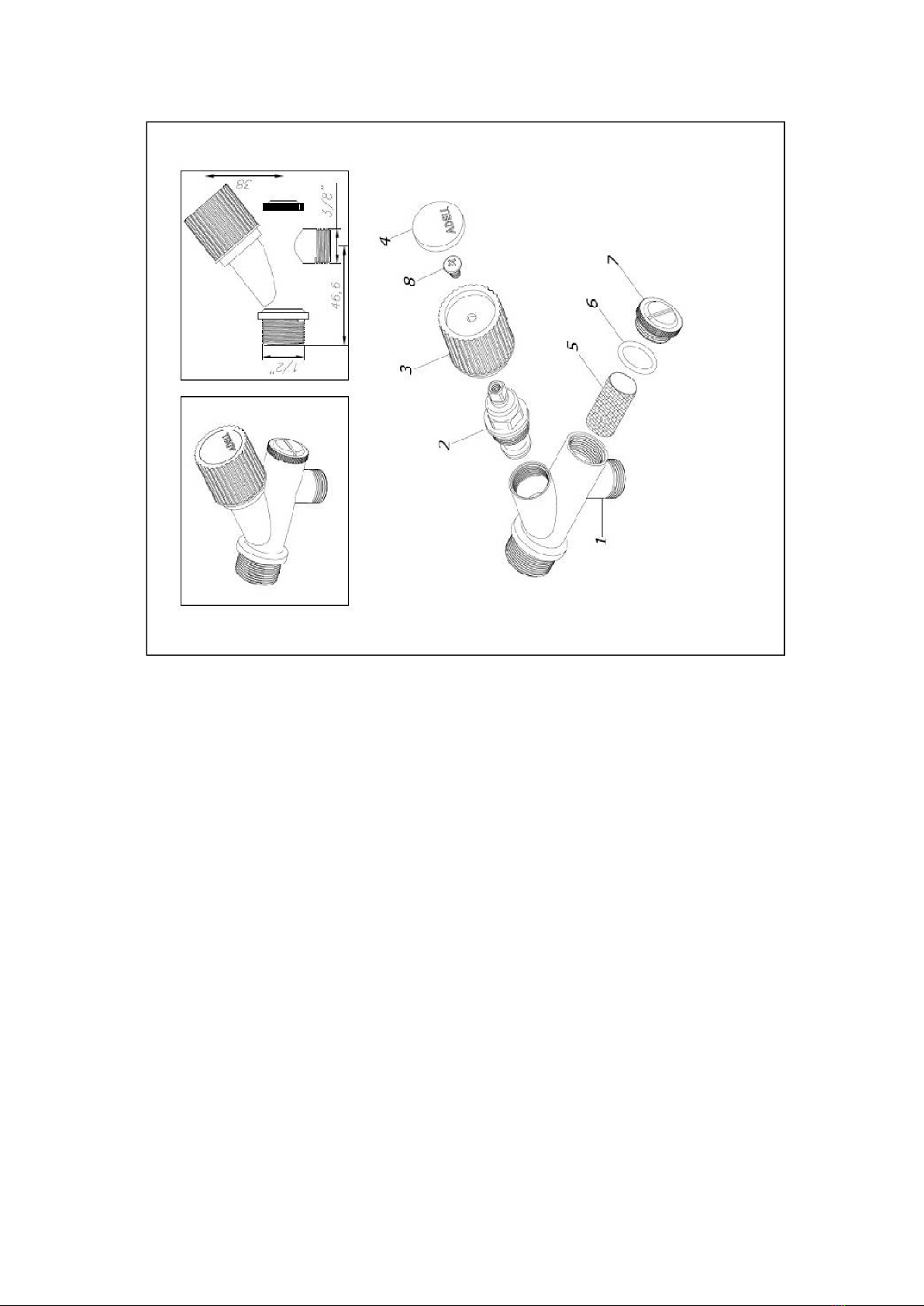
Filter no. 5 should be cleaned with compressed air and water regularly. Otherwise, the drain
solenoid valve may cause failure.
2GENERAL INFORMATION


a) When the dryer is switched on, it delivers the coolant to the system under high pressure and
temperature and the compressor operates continuously without fail.
b) The hot coolant is cooled down by fan in the condenser to make it liquid. And fan operation
is controlled by the pressure switch or heat sensor mounted at the condenser outlet.
c) The liquefied gas is stored in the liquid tank. And the coolant stored in liquid Is sprayed from
the liquid tank to the heat exchanger by means of expansion valve or capillary piping. This
expansion valve and capillary piping are protected by the particle-retaining filter coupled
with the dryer filter and body.
d) The coolant thus sprayed takes over the heat of the air passing through the heat exchanger
to cool it. While the compressed air is cooled down, the coolant in liquid form is converted
back to the gas phase and suctioned by the compressor. This closed circuit gas cycle
continues constantly.
e) In order to keep constant the pressure and temperature of the coolant in the heat
exchanger, hot gas is delivered from the hot gas delivery line of the compressor to the hot
gas return by means of a by-pass valve. And in case of some dryers, the pressure of the heat
exchanger is controlled by the expansion valves (regulator).
COMPRESSED AIR CIRCUIT
When the compressed air passes through the initial cooling circuit in the heat exchanger, it is mixed
with the compressed air cooled down to +3oC to perform initial cooling process. After passed the
initial cooling circuit, the air is cooled down to the intended temperature of 3oC at the section where
gas-air comparison is made. The compressed air cooled down Is discharged at the water separator by
the time-regulated drain valve.

Figure. Heat exchanger of he air dryer
3.1 FRONT PANEL


3.2 ON/OFF
Press on-off button ( ) and hold for 3 seconds to switch on the equipment. When the button
is held pressed, it counts 1---2---3 seconds on the display and the statement (open) ( )
appears on the display. To switch off the equipment, hold o-off button for 3 seconds again.
When the equipment is switched off, the statement (OFF) appears on the display and the
equipment is closed. When the equipment is closed, this statement appears on the display.
When you press the button (Drain Test) on the front panel, the equipment drains manually.
To have access to the set values of the equipment, press the buttons ( ) together for 3
seconds. In this menu:
TH: Setting the drain time. It drains each minute by the times set by means of the up-down
arrows (in seconds).
SR: The safety temperature value measured by the heat protection sensor is set. This setting
is made during the production stage at the plant!! (Temperature should be set according to
the type of the gas charged.)
SET: Operating set value of the equipment is adjusted. It may be set between 3oC and 10oC.
The default setting is set 3oC at the plant.
PRG: is selected in case of all versions.
3.3 CHARACTERISTICS OF THE AIR DRYER
Max series air driers have microprocessor controlled electronic board. 2 heat exchanger on this
board performs measurement continuously. The 1st sensor controls the dew temperature. And the
2nd sensor controls the condenser temperature of the equipment and, in some version, the
temperature of the refrigerating compressor to ensure the equipment to operate safely.
1. On the control board of the dryer, failure-warning contact output is achieved by FREE
contact.
2. In case of any failure, it gives audio alarm and the fault code appears on the display.
Air dryer is equipped with the control equipment to prevent any possible failure in the
occurrence of the following faults:
Condenser heat control sensor
(Versions between 900-3700 l/min.)
Compressor heat control sensor
(Versions above 5500 l/min)
Klixon high temperature switch
(All versions)
Low pressure switch
(All versions 5500 l/min and above)
Condenser high pressure switch
(All versions 5500 l/min and above))
Phase failure relay
(All versions 17,000 l/min. and above)
Compressor control switch
(All versions 25,000 l/min and above)
Fan control switch
(All versions 25,000 l/min and above)
Air dryer warns the user against the following faults by audio-visual warning on the front
panel
High pressure warning alarm
(All versions)
Sensor failure alarm
(All versions)
Cooling failure alarm
(All versions)
Freezing warning alarm
(All versions)
Service-maintenance time alarm
(All versions)
Low pressure warning alarm
(all versions 5500 l/min. and above)
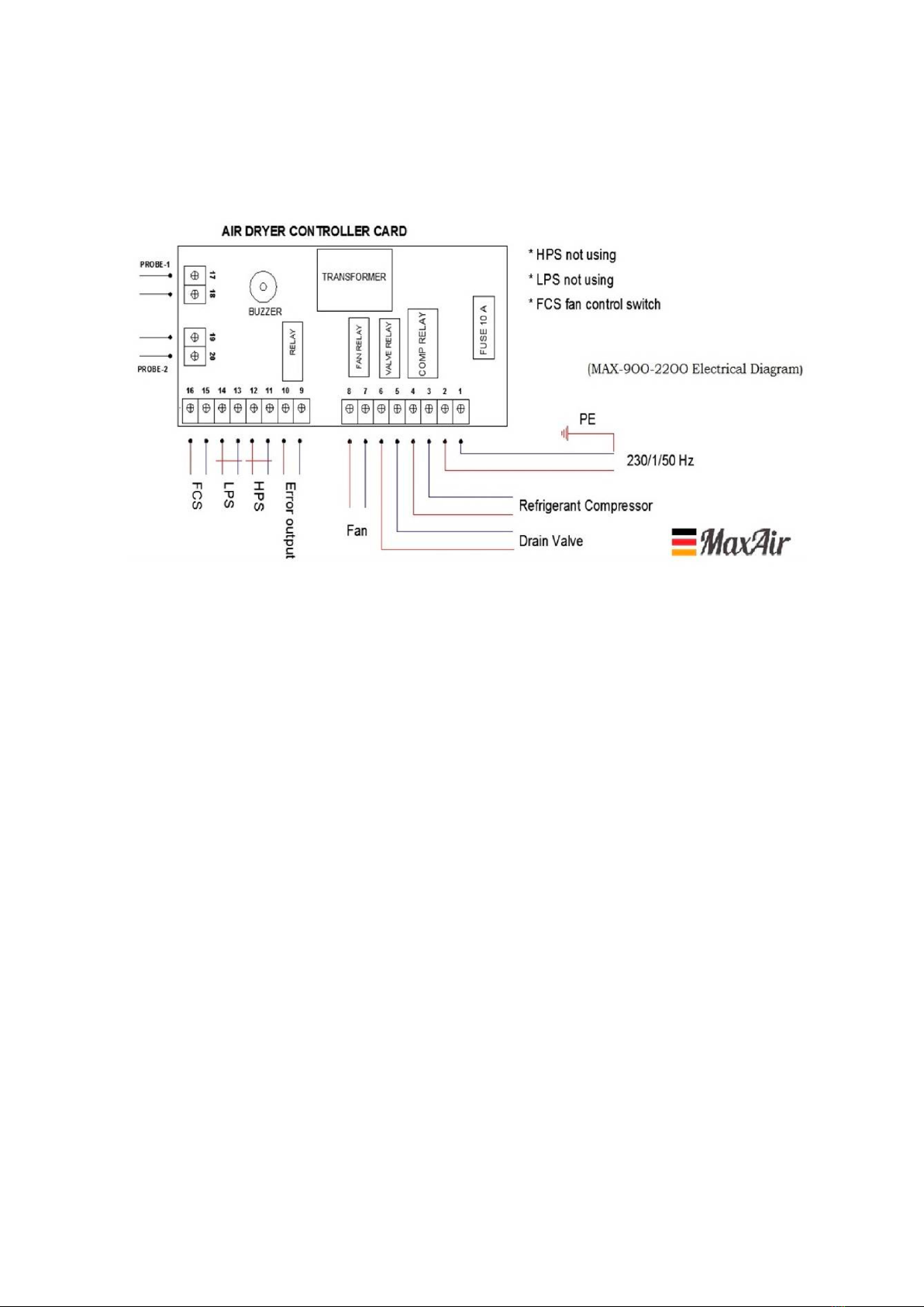
4. TECHNICAL SPECIFICATIONS AND DIAGRAMS
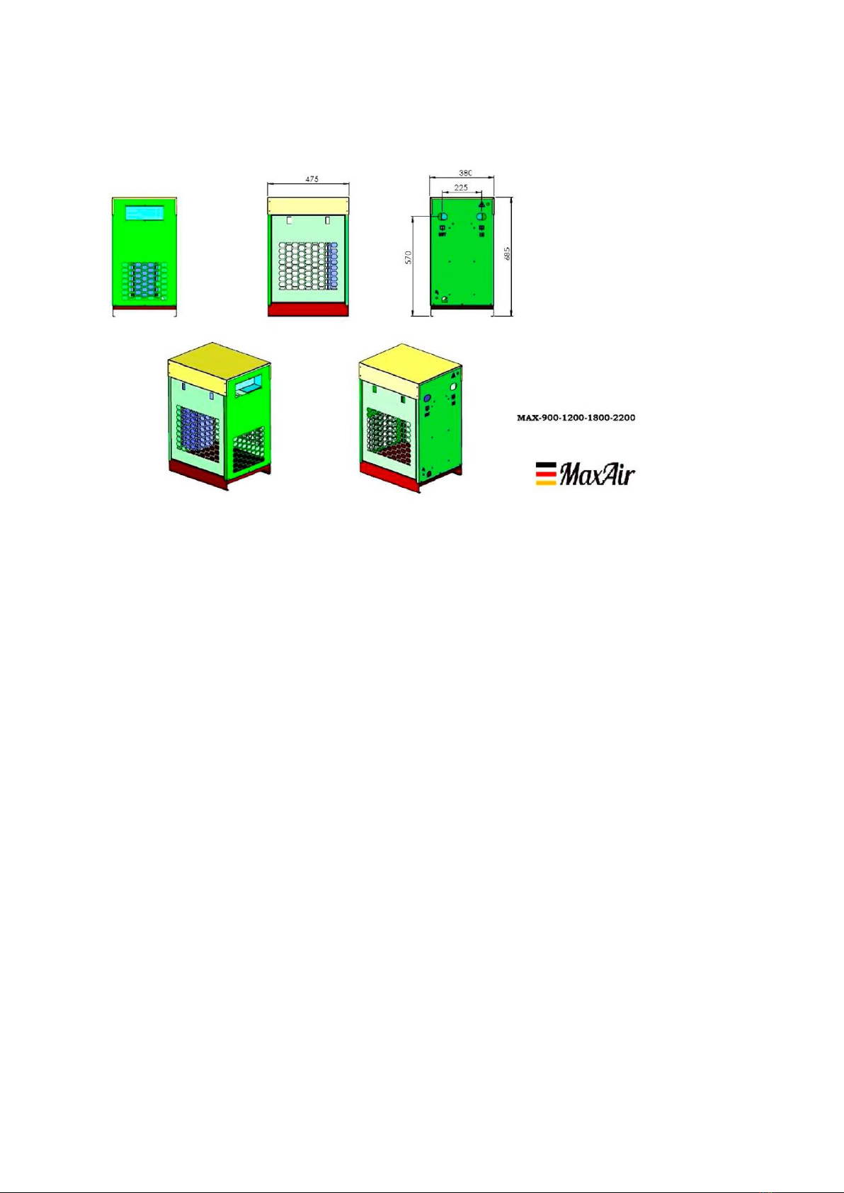


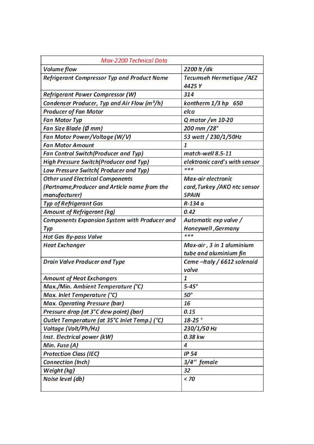

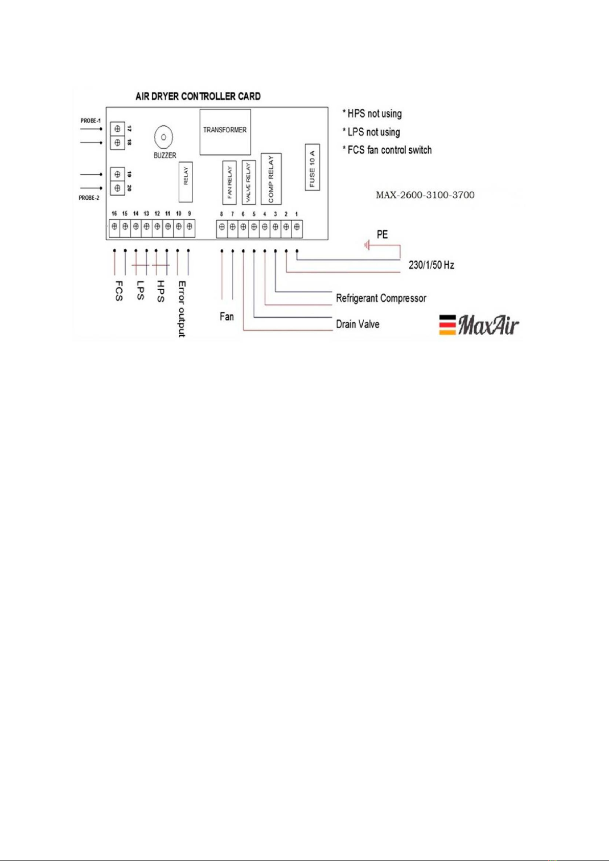
This manual suits for next models
19
Table of contents


