manuals.online logo
Brands
  1. Home
  2. •
  3. Brands
  4. •
  5. Maxcom
  6. •
  7. Switch
  8. •
  9. Maxcom MX1X2OS User manual

Maxcom MX1X2OS User manual

M
MX
X1
1X
X2
2O
OS
S
O
Op
pt
ti
ic
ca
al
l
S
Sw
wi
it
tc
ch
h
User manual
1
1. Product Overview
The MX1x2OS Optical switch is an important device in an optical fiber
communications system. It is mainly used as a backup switch of two-way optical
signals or multi-way optical signals. When the primary optical channel experiences
a fault, it automatically switches to the backup channel, ensuring the system’s
continued operation.
2. Features
■ High-performance switching components
■ Advanced 32-bit processor; automatic monitoring circuit; precisely monitors all
input power; auto switching mode and manual switching mode
■ 160 × 32 dot matrix LCD in the front panel
■ Standard 19"1U housing, Ethernet interface and RS-232 interface of
10Base-T/100Base-TX standard
■ Supports “GB/T 20030-2005 HFC network equipment management system
standard”.
3. Block diagram
4. Technical parameters
Item
Unit
parameter
remark
Operating wavelength
nm
1200 –1600
Insertion loss
dB
≤1.5
Test at the
position of
1310nm, 1490nm,
or 1550nm
2
Switching time
ms
≤ 5
Return loss
dB
≥ 55
Max input optical
power
mW
500
Range of input optical
power
dBm
-10 ~ +27
Switching life
≥10 million times
Connector type
FC/APC or SC/APC
voltage
V
AC160V - 250V(50 Hz)
consumption
W
≤ 2
Operating
temperature range
℃
-5 - +55
Max operating
relative humidity
%
Max 95% non-condensing
Storage temperature
range
℃
-30 - +70
Max storage humidity
%
Max 95% non-condensing
dimension
mm
483(W)×215(L)×44(H)
5. Function explanation
5.1 Front panel explanation
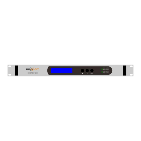
1: power indicator. It is on when the inner switching power is present.
2: indicator of A-channel output; it is green when the switch is at the position of
A-channel, and red at the position of B-channel
3: indicator of B-channel output: it is green when the switch is at the position of
B-channel, and red at the position of A-channel
4: alarm indicator: flickers when there is an alarm. The specific alarm content displays
in the menu.
5:160 × 32 dot matrix LCD: it displays all the parameters of the device.
6: left button - setting menu
7: up button
8: down button
9: right button
10. Cancel button
11. Ok button
3
5.2 back panel explanation
1. Input port of A-channel optical signal.
2. Output port of optical signal. When the equipment is operating normally, there is
invisible laser beam emitting from this port, so this port should not be towards to
the body or naked eyes, to avoid accidental injury.
3. Input port of B-channel signal
4. LAN interface: 10Base-T/100Base TX interface (Conforms to IEEE802.3-2002)
for the network management
5. RS232 Interface: used to configure the network management parameter of the
machine
6. Grounding stud
7. Installing port for fuse
8. AC110V power input port
5.3 Explanations of the displayed parameters
1. When the current of the switch is turned on, a menu entrance appears as follows.
Press “ok” to enter the main menu.
Current working channel and model
You may press any direction key to switch the sub-menu between parameter
menu and alarm menu.
Displayed parameters
Displayed contents
meaning
Input optical power ofA-channel
Input optical power of B-channel
Output optical power
Current control mode, press “ok” to
set.
4
Current work channel
Work channel in manual mode, press
“ok” to set.
Switch threshold of auto control mode,
when the input power of A-channel is less
than this value,the working channel will
automatically switch to B. You can press
“ok” to set.
Wavelength of the system. This value
is set to adjust the accuracy of input
optical power.
The current unit temperature
LCD contrast, press “ok” to set.
Alarm switch of buzzer, press “ok” to
set.
System date, press “ok” to set.
System time, press “ok” to set.
IP of the machine, press “ok” to set.
The gateway, press “ok” to set
Subnet mask,press “ok” to set
MAC address of the machine
5
Serial number of the machine
Version number of the soft system
Cumulative working time
2. Press any direction key, and then entrance of alarm menu appears. Now you
can press “ok” to enter it.
Displayed alarm contents
Displayed contents
meaning
Input optical power alarm of port A.
content in the brackets is the alarm
state. It is low alarm in the picture.
Input optical power alarm of port B.
content in the brackets is the alarm
state. It is low alarm in the picture.
There is no other alarm.
6. Explanation of the network management
6.1 interface
1) RS232 communication interface(CONSOLE)
This interface adopts standard DB9 female connector, the foot position is defined
as follows:
1:No Connect
2:TX
3:RX
6
4:No Connect
5:GND
6:No Connect
7:No Connect
8:No Connect
9:No Connect
This equipment’s serial communication uses standard NRZ format, start bit is 1-bit,
data bit is 8-bit, stop bit is 1-bit, and the baud rate is 115200.
2) LAN communication interface
It uses standard RJ45 connectors; the foot position is defined as follows:
1:TX+
2:TX-
3:RX+
4:No Connect
5:No Connect
6:RX-
7:No Connect
8:No Connect
6.2 The configuration of operating parameters
In the case that power is off, connecting the RS232 port and computer’s serial port
with a serial line, opening the Windows HyperTerminal, and then turning on the
power supply, you will see the following pictures. At the time, you can press "Enter"
7
key in your PC keyboard to enter the bootstrap program, and create some advanced
configuration. The bootstrap program looks like BIOS setup program in PC. In
general, there is no need for the user to enter the bootstrap program to set parameters,
so we added a password for the bootstrap program to prevent destroying the normal
configuration.
Skip the bootstrap program, the application is started normally, as follows:
With this method, you can input commands in this interface, and configure relevant
operating parameters.
The system supports following commands:
help list the system command
ethcfg configure the Ethernet operating parameters
trap configure the Host IPaddress of SNMPTrap
comnty configure SNMPcommunity name
model configure the information of LOGO
8
The specific usage:
help
This command is used to display the version number, the program name, and the
command list of system.
You can also use the “help” command to display help information of other commands.
For example, "help ethcfg", then following picture appears:
ethcfg
It is used to configure the Ethernet parameters, including IP address, subnet mask, and
gateway.
9
As to the usage, you can refer to such command’s help information.
trap
This command is used to display or modify the IP address list that SNMP trap sends
to the host. Trap-l command displays the target server list; trap-m command modifies
the target server list, as follows:
If the IP address is 0.0.0.0 or 255.255.255.255, it indicates these addresses are
non-existent and the SNMP trap will not be sent to these addresses.
comnty
This command is used to configure the SNMP read-only community names and
read-write community names. "Group name" is the concept of SNMP protocol, which
is equivalent of SNMP password. You can set read-only community name with the
command "comnty ro", and set read-write community name by using "comnty rw". In
the example of inputting "comnty rw public", the "public" is read-write community
name. If no parameter is added, the read-only and the read-write community names
are displayed.
10
Note: 1. In the cleaning process for the optical fiber connector, the connector should
not be aimed to the body or eyes, this may cause permanent injury.
2. The force used to install the optical fiber connector must be appropriate, or it
may damage the ceramic tube in the adapter. If it is damaged, the Output
Power will decline.
3. Any operation to the optical fiber should be done in the case that the pump
laser is turned off; otherwise the high-power output may potentially burn out
or damage the optical fiber connector.

Other Maxcom Switch manuals

Maxcom MX 1x2 RF Series User manual

Maxcom

Maxcom MX 1x2 RF Series User manual

Maxcom MX-OFSW-2X1 User manual

Maxcom

Maxcom MX-OFSW-2X1 User manual

Popular Switch manuals by other brands

APG LF Series Operator's manual

APG

APG LF Series Operator's manual

Mellanox Technologies SX6518-NR Hardware installation guide

Mellanox Technologies

Mellanox Technologies SX6518-NR Hardware installation guide

BeeControls iBeeSwitch iBKSW-BEE YZZ Series quick start guide

BeeControls

BeeControls iBeeSwitch iBKSW-BEE YZZ Series quick start guide

Force 10 S50 installation guide

Force 10

Force 10 S50 installation guide

Siemens RUGGEDCOM RX1500 installation guide

Siemens

Siemens RUGGEDCOM RX1500 installation guide

Cisco Catalyst 9300 Series Hardware installation guide

Cisco

Cisco Catalyst 9300 Series Hardware installation guide

Digisol DG-FS1526 user manual

Digisol

Digisol DG-FS1526 user manual

Balluff BNI IOL-302-002-Z046 user guide

Balluff

Balluff BNI IOL-302-002-Z046 user guide

Moxa Technologies EDS-P206A-4PoE-SS-SC Hardware installation guide

Moxa Technologies

Moxa Technologies EDS-P206A-4PoE-SS-SC Hardware installation guide

Phonak Roger AudioHub user guide

Phonak

Phonak Roger AudioHub user guide

Zenty ZT-105 user manual

Zenty

Zenty ZT-105 user manual

Transition Networks SM24-100SFP-AH Specifications

Transition Networks

Transition Networks SM24-100SFP-AH Specifications

Brocade Communications Systems FastIron SuperX Hardware installation guide

Brocade Communications Systems

Brocade Communications Systems FastIron SuperX Hardware installation guide

Planex SF-0424F Quick installation guide

Planex

Planex SF-0424F Quick installation guide

KYLAND Technology SICOM Series Configuration manual

KYLAND Technology

KYLAND Technology SICOM Series Configuration manual

Elkay pushbutton Fitting and operating instructions

Elkay

Elkay pushbutton Fitting and operating instructions

Automatic Door Accessories ADA 215S Operation instructions

Automatic Door Accessories

Automatic Door Accessories ADA 215S Operation instructions

Gefen 2X1 DVI KVM SWITCHER user manual

Gefen

Gefen 2X1 DVI KVM SWITCHER user manual

manuals.online logo
manuals.online logoBrands
  • About & Mission
  • Contact us
  • Privacy Policy
  • Terms and Conditions

Copyright 2025 Manuals.Online. All Rights Reserved.