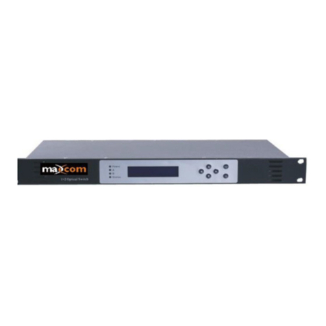
Maxcom MX-OFSW-2X1 User manual

M
MX
X-
-O
OF
FS
SW
W-
-2
2X
X1
1
O
Op
pt
ti
ic
ca
al
l
F
Fi
ib
be
er
r
2
2×
×1
1
S
Sw
wi
it
tc
ch
h
U
US
SE
ER
R
M
MA
AN
NU
UA
AL
L
CONTENT
1.0 PRODUCT SUMMARY ........................................................................2
2.0 CONTROLS, INDICATORS, AND ALARMS ..........................................2
2.1 Menu and operation of the control panel ............................................. 2
3.0 OPERATIONAL PROCEDURE .............................................................4

1.0 PRODUCT SUMMARY
The MXOFSW-2X1 is a 2×1 prism optical switch. It will support two optical fibers input
and one fiber output with an auto detect switch. The unit supports a wide operating
wavelength range and a quick switching rate.
The MXOFSW-2X1- has two operational modes:
①Manual mode:
Through the LCD control interface or network, the user may trigger a switch of the fiber
route in real time.
②Automatic mode:
Automatically detects and switches fiber inputs based on the parameters set by the user or
requirement (example: if input A is set to -5 dBm, and if the input power drops to a level
below -5 dBm, the unit will automatically switch to input B. Note the unit will switch back to
input A once the level is restored to a value higher than -5 dBm).
*Note, Output B is optional and does not exist on this model.
The MXOFSW-2X1 is mounted in a 19” rack 1U chassis. The LCD is located at the front
panel and provides all operating parameters and the current operator scheme. The RS232
interface and RJ45 ethernet interface, for SNMP, provide remote management and control.
2.0 CONTROLS, INDICATORS, AND ALARMS
This section of the manual will give a brief overview of the available menus in the
MXOFSW-2X1 series optical switch and their descriptions. All instructions in Section 2.0
refer to the representation of the front panel shown in the diagram below. The user
may scroll through the menu using the push buttons found on the front panel, these are
located just on the right of the LCD screen.
2.1 The menu and operation of the control panel
2.1.1 Boot order
A. Connect power supply.
B. Turn on power switch on the rear panel.
In order to make sure this device is working safely, the power supply of this device has
a time delay function, when turned on, there is a delay of a few seconds. The status
indicator will turn to green from red. The Digital panel displays the model of this
device.

2.1.2 Start-up main menu
Pressing Select button will display below menu in sequence.
Menu # 1 - Descriptor
Read-only menu, indicates the description of this equipment.
Menu # 2 - INPUT A
Adjustable menu, indicates wavelength selection of A path
Menu # 3 - INPUT B
Adjustable menu, indicates wavelength selection of B path
Menu # 4 - INPUT A
Read-only menu, indicates the input optical power of INPUT A
Menu # 5 - INPUT B
Read-only menu, indicates the input optical power of INPUT B
Menu # 6 - OUTPUT
Read-only menu, indicates the output optical power (measured before
switch loss)
Menu # 7 - Switch Type
Read-only menu, indicates the optical switch type
Menu # 8 - Switch Mode
Adjustable menu, displays the optical switch mode
Menu # 9 - UNIT TEMP
Read-only menu, indicates the temperature of unit
Menu # 10 - +5V monitor.
Read-only menu, indicates the +5V voltage monitor.
Menu # 11 - -5V monitor.
Read-only menu, indicates -5V voltage monitor
Menu # 12 - OPTIC SWITCH POINT
Adjustable menu, displays the current optic switch point.
Menu # 13 - IP
Adjustable menu, displays the IP address of SNMP
Menu # 14 - SUBMASK
Adjustable menu, displays the address of sub net mask
Menu # 15 - GATEWAY
Adjustable menu, displays the gateway address of SNMP.
Menu # 16 - TRAP ADDR1
Adjustable menu, displays the TRAP1 address of SNMP.
Menu # 17 - TRAP ADDR2
Adjustable menu, displays the TRAP2 address of SNMP
Menu # 18 - S/N
Read-only menu, indicates the serial-number

2.1.2 Menu assistant manual
1. Set INPUT A/B
Under the menu of INPUTA/B, press button to enter the sub menu and to
select and modify value. Press button to select wavelength, press SELECT
button to save and exit.
When the Switch Mode is selected as “Manual: A to 1;B to 2”, select main
channel output.
2. Set optical switch mode
Under the menu of the Switch Mode, press to enter into sub-menu to amend.
Press to select the switch mode, then press Select to save and exit.
3. Set optic switch point
Under the menu of the Optic Switch Point, press to enter into sub-menu to
amend. Press to select the optic switch point, then press Select to save and exit.
The value range may be set to +10 dBm to -10 dBm
4. Set the IP address
Under the menu of IP, SUBMASK, GATEWAY, TRAP ADDR1, TRAP ADDR2, press
button enter into sub menu to select modify value. Press to change the value,
then press Select to save and exit.
3.0 OPERATION METHOD
Four indicators on the front panel show which light path is being used. Inputs are
represented by A and B respectively, where A is the main input and B is the backup
input. The main and standby optical paths are automatically switched:
The user can set the Optic Switch Point. This value on the primary input (input A) may
be set between +10 dBm and -10 dBm. Once this is set, the unit will automatically
switch to the secondary (input B) if this value falls below the setting. For example, if the
Optic Switch Point value is set to -3 dBm, the unit will switch to the secondary if the
optical power of input A falls below -3 dBm.
* If optical signal powers are both less than switch point power, the device will maintain
the current state.
www.maxcomcorp.com 209-339-2333

Supplemental: Web Interface
The MX-OFSW-2x1 may also be accessed from a web interface using the RJ45 port.
The web interface can be viewed using the default IP address 192.168.1.50
The default username is “admin”, and the default password is “admin”
The categories will be displayed on the left side of the screen as follows:
IP Configuration –this feature allows you to modify the IP address and trap
information.
Analog Property –This page is pre-configured from the factory but may be
modified. These values represent the alarm thresholds.
Discrete Property –Future Feature - This feature is currently not active but is
planned for system power monitoring.
Device Configuration –Allows the user to set switch to automatic or allows user
to perform a manual switch. This also allows the user to select a switch point
between -10 dBm and +10 dBm (this value allows the switch to automatically
execute a switch when the Primary input (A) falls below this value.
Device Status –displays optical power, voltage, and temperature.
System Info –Provides the model, serial, and version numbers. You may add a
name and other info here.
Event Log –This screen displays a record of events or alarms
User Configuration –Allows the user to change username or password
www.maxcomcorp.com 209-339-2333

Performance
Index
Supplement
Min.
Typ.
Max.
Optical
features
Insertion loss
(dB)
1.6
2.5
Return loss
(dB)
55
60
Switch cross talk
(dB)
55
60
PDL
(dB)
0.2
Switching time
(mS)
20
Fiber type
9 / 125
Optical connector
SC/APC
Optional
available
General
feature
10/100M Ethernet
interface
RJ45
Networking protocol
SNMP
Communication
interface
RS232
Power supply
(VAC)
90
265
50 / 60Hz
Operating temp.
(℃)
-20
65
Storage temp.
(℃)
-40
85
Relative humidity
(%)
5
95
Size (W) x (D) x (H)
19×10×1.75 ( " )
1U
483×254×44 ( mm )
www.maxcomcorp.com 209-339-2333
Table of contents
Other Maxcom Switch manuals
Popular Switch manuals by other brands

3Com
3Com 3C17708-US - Switch 4050 Getting started guide

D-Link
D-Link DSS-5 - 10/100 Switch, Desktop user guide

Proscend
Proscend 708EPI-DC Quick installation guide

TRENDnet
TRENDnet TI-G102 Quick installation guide

steute
steute RF I/O SW868-4E-2,2Ah Mounting and wiring instructions

D-Link
D-Link xStack DGS-3600 Series user manual

Renkforce
Renkforce 2623966 operating instructions

Brocade Communications Systems
Brocade Communications Systems ICX 6610 series installation guide

VICOR
VICOR PFC Mini user guide

PulseWorx
PulseWorx RM1-15 Installation guide and owner's manual

TRENDnet
TRENDnet TO-PG541 Quick installation guide

Kramer
Kramer AFM-20DSP quick start guide