manuals.online logo
Brands
  1. Home
  2. •
  3. Brands
  4. •
  5. Maxford USA
  6. •
  7. Toy
  8. •
  9. Maxford USA Curtiss Pusher User manual

Maxford USA Curtiss Pusher User manual

Copyright 2015 Maxford USA Page 1 of 22 pages #S150422
C
CU
UR
RT
TI
IS
SS
S
P
PU
US
SH
HE
ER
R
SPORT-SCALE ARF R/C EP MODEL AIRPLANE
I N S T R U C T I O N M A N U A L
The Curtiss Model D was often called the Curtiss Pusher because practically all were built with their
propellers ‘pushing’ from behind their pilots. Much more importantly, since the Wright Brothers’
patents prevented Glenn Curtiss from using wing warping for lateral control, he designed his Model D
with ailerons, which turned out to be the far superior method for achieving lateral control. Early
examples of the Curtiss Pusher had an elevator at the front for pitch control with a horizontal stabilizer
at the rear. The front elevator was ultimately discovered to be unnecessary, resulting in the later
development of the Curtiss “Headless”Pusher.
This sport-scale ARF R/C electric-powered Model D is based on the early-production “Headed”
Curtiss Pusher and is built to approx. 1/9 scale. It is constructed from balsa, plywood and composite
materials and comes prefinished with a two-color Mylar covering scheme.
Two flights of the Headed Curtiss Pusher formed the strong beginnings of a relationship between
Glenn Curtiss and the Navy that remained strong for decades: On November 14, 1910, test pilot
Eugene Ely took off from the USS Birmingham, which was the first time any aircraft successfully took
off and flew from a ship; then, on January 18, 1911, Eugene Ely performed the second precursor to
modern-day Navy aircraft-carrier air operations by landing a Model D aboard the USS Pennsylvania in
the first arrester-cable landing on a ship. In April 1911, the Navy purchased the Model D for use as an
airborne observation platform and the Aeronautical Division of the U.S. Army Signal Corps purchased
the Model D to use as a trainer. Consequently, the Curtiss Model D pusher became among the first
aircraft in the world to be built in any quantity.
We invite you to enjoy the pride of ownership and the joy of flying
this beautiful ARF sport-scale model of the famous Curtiss Pusher.
Shown in flight with optional simulated pilot,
electric power system, receiver and servos.
Copyright 2015 Maxford USA Page 2 of 22 pages #S150422
TABLE OF CONTENTS:
I.
Important safety precautions ...………….................
2
V.
Special features ……………………….................
5
II.
Warranty, liability waiver & return policy ..........
3
VI.
Assembly instructions ..……….......................
5
III.
Specifications ..……………………………………...........
4
VII.
Setup & adjustments ........................................
20
IV.
Parts List .….…………………………………………………
4
VIII.
Storage, field setup & preflight checks ....
22
I. SAFETY PRECAUTIONS & ASSEMBLY TIPS
(IMPORTANT –READ THIS SECTION BEFORE YOU BEGIN ASSEMBLY)
1. This product should not be considered a toy, but rather a sophisticated, working model that
functions much like a full-scale airplane. Because of its performance capabilities, this product, if
not assembled and operated correctly, could cause injury to you or spectators and damage to
property. Maxford USA provides you with a high-quality, thoroughly tested model airplane kit with
assembly instructions. However, the quality and capabilities of your finished model airplane
depend on how you assemble it, and your safety depends on how you use and fly it. Any testing or
flying of this model airplane is done entirely at your own risk.
2. Assemble this model airplane according to these instructions. Do not alter or modify the model
beyond the assembly and power-system options covered in these instructions, as doing so may
result in an unsafe or unworkable model. If the instructions differ from the photos, the written
instructions should be considered correct. If you have any question or concern about these
instructions, before you proceed with assembly of this product, contact your dealer or speak to a
Maxford USA customer service representative at 562-529-3988 (Monday through Friday, except
national holidays, 9 AM to 5 PM Pacific Time).
3. While this kit has been flight-tested to meet or exceed our rigid performance and reliability
standards in normal use, if you elect to perform any extremely high-stress flying, such as racing or
advanced aerobatics, or if you install a much larger power system than specified, you (the buyer or
user of this product) are solely responsible for taking any and all necessary steps to reinforce the
high-stress points and/or substitute hardware that is more suitable for such increased stresses.
4. Throughout the lifetime of this model, use only the Maxford USA-recommended power system and
a new or well-maintained radio-control system.
5. It is your responsibility to install the receiver and connect the R/C components in such a way that
this model airplane passes all applicable safety/range tests and that the power system and
controls operate correctly and smoothly.
6. Recheck the operation of this model airplane before every flight to ensure that all equipment is
still operating correctly and that the model has remained structurally sound. Also before every
flight, check all electrical, control and structural connections; do not fly without replacing any that
you find damaged or worn.
7. Before you begin assembly of this model airplane, read all instructions and test-fit each part to
ensure you fully understand the instructions and that no parts are missing, damaged or
unsatisfactory. Temperature and/or humidity differences between the factory, our warehouse and
your home or workshop may dictate the need for slight adjustments to the wings, struts and/or
the horizontal stabilizer’s mounting surfaces to ensure proper alignment; we recommend you
contact us before attempting any such adjustments.
8. To help ensure the security of your servo connections, we recommend use of optional
Maxford USA servo-extension safety clips as pictured at the right. (For information
about safety clips see http://www.maxfordusa.com/servoextensionsafetyclip.aspx.)
9. Assemble EZ-Link connectors as shown
at the far right. When applying thread-
lock compound or CA adhesive, do NOT
glue the EZ-Link connector to the
control arm or mounting tab. Also, be
careful to not let the pushrod rub or
bind against nearby surfaces.
Clamping bolt
Connector body
Control arm (or mounting tab)
Washer
Mounting nut
Copyright 2015 Maxford USA Page 3 of 22 pages #S150422
10. We recommend using your radio or a servo tester to center your servos before installation. (You
may learn more about servo testers at http://www.maxfordusa.com/servo.aspx.)
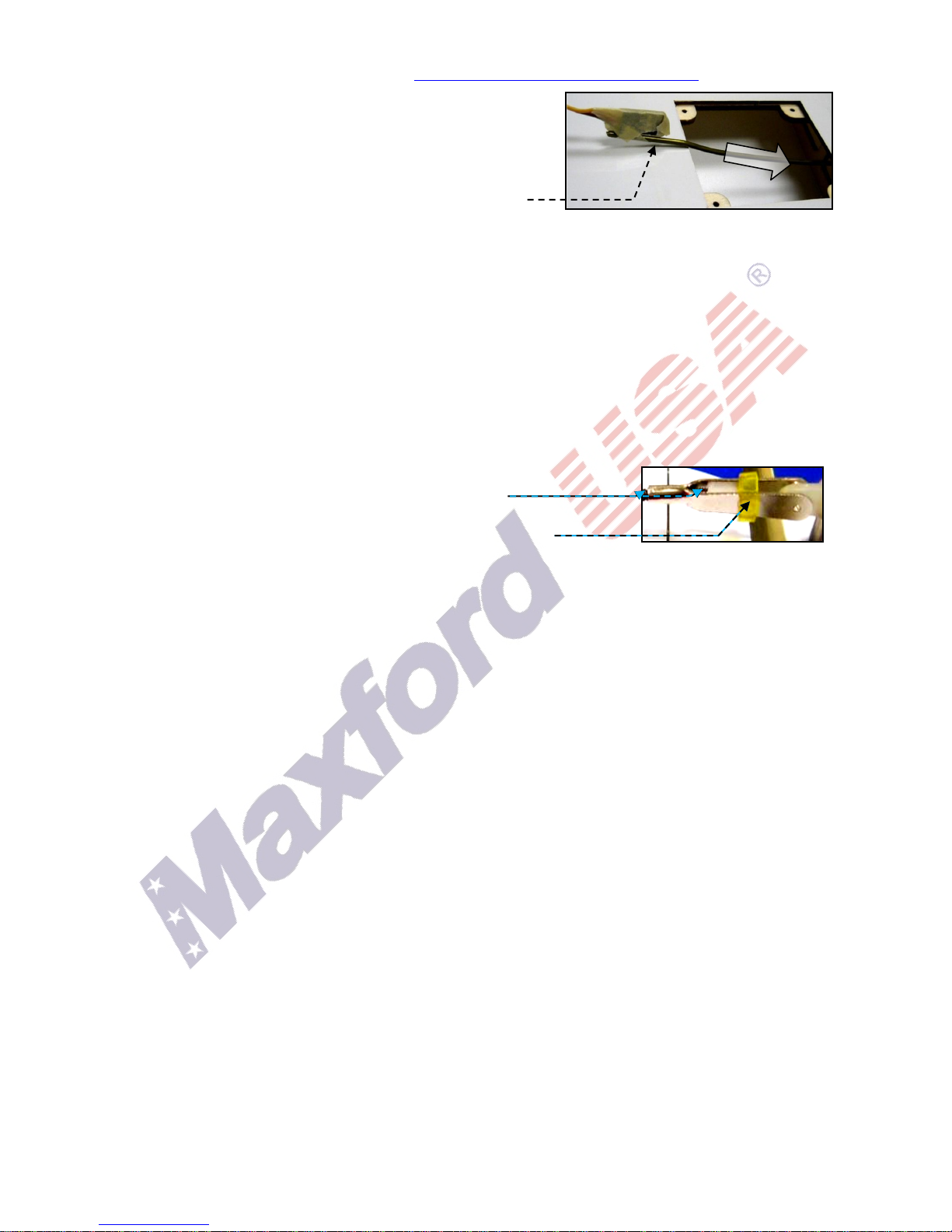
11. String may be supplied to pull your servo’s lead and
servo extension through the wing to your radio receiver;
however, you may find it easier to use masking tape to
temporarily attach the connector to the end of a length of
coat hanger wire, then use the wire to pull the lead and
connector through the airframe as shown at the right.
12. After you have determined each wood-screw’s location, apply thin CA adhesive to harden and
strengthen the wood where the screws are to be inserted.
13. If Mylar hides a CA hinge’s slot, find and open the slot by carefully pressing with a fingernail or
sharp hobby knife.
14. If you are not an experienced ARF assembler or R/C pilot or if you have not flown this type of
model before, we strongly urge you to get assistance from an experienced R/C pilot.
15. You may use epoxy to attach critical parts permanently (such as where the front and rear booms
attach to the upper and lower wing’s center sections and where the horizontal stabilizer attaches
to the tail booms). Apply a threadlock compound to secure all airframe hardware from vibration.
16. If you have concern about the security of any factory fabrication procedure(s), you may apply
extra 5 minute epoxy around the perimeter of such part(s) as a safety precaution.
17. After adjusting each clevis, secure the clevis to its threaded rod
with threadlock compound, epoxy, or CA adhesive.
For additional safety, you may hold the clevis closed by adding a
small piece of tubing (not supplied) as shown at the right.
(NOTE: This model may be packaged with clevises made of either plastic or metal.)
18. Since this model includes some plastic, fiberglass and/or carbon-fiber-reinforced parts, if you drill,
grind or sand any such part, be sure to wear safety goggles, a particle mask and rubber gloves to
guard yourself from eye, skin and respiratory-tract irritation; never blow into the part as the dust
may blow back into your face.
19. Minor production details (such as included hardware items and Mylar or paint colors) may vary.
20. Periodically check the Mylar covering material’s joints and surfaces; if necessary, carefully use an
iron (do NOT set the iron’s temperature too high) to secure the edges and to tighten any loosened
areas.
21. Read all instructions included with your motor, electric speed control, battery and charger. Failure
to follow all instructions could result in permanent damage to these items, their surroundings, and
possible bodily harm! If you crash this model airplane, carefully check whether your battery is
damaged. Do NOT attempt to use or recharge a damaged battery.
II. LIMITED WARRANTY, LIABILITY WAIVER & RETURN POLICY
Maxford USA guarantees this kit to be free from defects in material and workmanship at the time
of purchase. All our products have been inspected in our factory and are checked again when
shipped from our warehouse. However, Maxford USA cannot directly control the materials you
may use or your final assembly process. Therefore, Maxford USA cannot in any way guarantee the
performance of your finished model airplane. Furthermore, in purchasing this product, you (the
buyer or user of this product) exempt, waive, and relieve Maxford USA from all current or future
liability for any personal injury, property damage, or wrongful death, and if you (the buyer or user
of this product) are involved in any claim or suit, you will not sue Maxford USA or any of its
representatives.
If you do not fully accept the above liability and waiver, you may request a return-merchandise
authorization number (RMA#) as explained below in item 2. If you think there is a missing,
damaged or unsatisfactory part, please read our after-sales service and return policy:
1. Inspect your order upon delivery for any missing, damaged or unsatisfactory part(s). If you
believe there is a problem, you must call us at 562-529-3988 (Monday through Friday except
holidays, between the hours of 9 AM and 5 PM Pacific time) before you begin assembly and
Copyright 2015 Maxford USA Page 4 of 22 pages #S150422
within 10 days from receipt of your purchase. During this telephone conversation, and with
your support, we will determine how to resolve your concern.
2. To request a return-merchandise authorization number (RMA#), call 562-529-3988 (Monday
through Friday except holidays, between the hours of 9 AM and 5 PM Pacific Time). If we elect
to issue you an RMA#, you must clearly mark this RMA# on the outside of the package. (No
return or exchange will be authorized after 10 days from the date of your receipt of the product;
any package delivered to us without a Maxford USA RMA# is subject to being returned to the
sender, as received, with return postage payable upon delivery.) Returned merchandise must
be in its original condition as received from Maxford USA, with no assembly or modification, in
the product’s original packing materials, complete with all manuals and accessories. Return
shipping and insurance charges must be prepaid by you, the buyer.
3. Returned merchandise that is accepted by Maxford USA for credit is subject to a 10% to 20%
restocking fee (the final amount will be determined by Maxford USA upon receipt and
examination of the returned merchandise).
Return address: Maxford USA
15939 Illinois Avenue, #B-C
Paramount, CA 90723 (Print the RMA# issued by Maxford USA
on your package near our address.)
III. SPECIFICATIONS
Wingspan ......................................................................................................................................................... 50 inches
Length ............................................................................................................................................................ 48.5 inches
Wing area ....................................................................................................................................... 788 square inches
Radio ..................................................................................................................................... Minimum of 4 channels
with 5 mini servos
Flying weight .............................. Around 5.5 to 6 pounds (depending on power and radio systems)
Minimum power ................................................................................................................ 400W brushless motor
Propeller ........................................ 10x6 to 11x7 or as recommended by your power system’s maker
(Dimensions and weights are approximate)
IV. PARTS LIST
1. Included items
Prebuilt and precovered flying surfaces.
Scale-looking tricycle landing-gear.
Composite struts and braces.
Pilot’s seat.
Adjustable motor mounting box.
Included standard wheels.
Scale stick-on markings.
Hardware package.
Articulated pilot’s
elevator-control stick.
2. Items you must supply to complete this ARF
Epoxy and cyanoacrylate (CA) adhesives and threadlock compound.
Common hand tools (screwdriver, pliers, etc.).
Outer rotor motor and electronic speed control (ESC) such as the Maxford USA Uranus 35425
motor and 60A ESC with a 3S or 4S approx. 3,000
mAh LiPo battery, or as recommended for your
motor, and a LiPo battery charger suitable for your
battery.
A four- (or more) channel radio system with five
mini servos; two 24-inch, three 10-inch and two
6-inch servo extensions and two 6-inch Y harnesses.
(Extension lengths may vary, depending on your
installation and choice of radio system components.)
A 10- or 11-inch diameter x 6- or 7-inch pitch
propeller, or as specified for your motor.
*
*
Copyright 2015 Maxford USA Page 5 of 22 pages #S150422
3. Optional items you
may choose to add
Vintage-style 2 1/2-inch diameter spoked
wheels. (NOTE: This model includes the
standard wheels pictured on instruction
manual pages 1 and 4. Learn about spoked at
http://www.maxfordusa.com/vintagestyle3
spokedwheels.aspx.)
Maxford USA 1/5 scale pilot figure.
Servo extension safety clips.
V. SPECIAL FEATURES
Unique model of this historic pre-World War I aircraft.
Functional front and rear elevators.
Articulated pilot’s control stick.
Scale-looking functional ailerons.
Tricycle landing gear.
Constructed mainly of jig-assembled, laser-cut balsa and light plywood, with composite wing
rods, struts and airframe components.
Precovered scale-looking wings with cream color on top and semi-transparent on the bottom.
Adjustable-depth motor-mounting box, able to accept a wide range of power system options.
Outer wing panels are removable for easy transport and storage.
Black string, swivels and springs are supplied to simulate wing wires and tail-boom bracing.
Replacement parts and optional detail-upgrade items are available.
VI. ASSEMBLY INSTRUCTIONS
1. Locate the openings for the struts and engine-mounting bearers in the bottom of the top wing’s
center section. Set the top wing’s center section aside.
2. Locate the openings for the struts and engine-mounting bearers in the top of the lower wing’s
center section. (NOTE: As shown below, the openings for the engine-mounting bearers are
between 2 extra-wide ribs near the middle of the lower wing’s center section at approx. 1 1/2-
inches in front of the trailing edge and 1/4-inch behind the leading edge.)
Locations of the 4 openings for
the engine-mounting bearers in
the lower wing’s center section.
Approx.
11/2-inch
Leading
edge
Trailing
edge
Approx. 1/4-inch
Copyright 2015 Maxford USA Page 6 of 22 pages #S150422
3. To determine how to correctly position the vertical engine-bearer struts in their openings in the
top of the lower wing’s center section:
a) Position the engine-bearer assemblies with
the horizontal engine bearers at approx. 90
degrees to the vertical engine bearers as
shown at the right. Observe that the end of
one of the vertical engine bearers is about
1/4-inch higher than the other. The ‘higher’
vertical engine bearer will be installed near
the leading edge; the ‘lower’ vertical engine
bearer will be placed near the trailing edge.
b) Observe the bolts that connect the vertical
and horizontal engine bearers: When the
engine bearer assemblies are correctly
positioned, the heads of these bolts will be
facing each other.
4. Being careful to
face the heads of
the bolts toward
each other, test-fit
the ‘HIGHER’vertical
engine bearers into
the openings near
the leading edge of
the lower wing’s
center section and
the ‘LOWER’ vertical
engine bearers into
the openings near the trailing edge. (NOTE: Do not poke accidently any ‘extra’ holes in the Mylar.)
5. As shown below, test-fit the horizontal stabilizer into the slot at the rear of each tail boom.
(NOTE: The tail boom’s SHORTER struts and the horizontal stabilizer’s TAN side are both at the TOP.)
6. Test-fit a servo tray under each side of the hori-
zontal stabilizer above the lower tail booms.
7. Position the vertical braces
in front of the horizontal
stabilizer into the notched
openings as pictured
at the right.
8. Tighten all the 2mm dia. bolts
into the nuts on both tail boom
assemblies.
90º
Install the ‘lower’
vertical engine
bearer near the
trailing edge.
90º
Top horizontal engine bearer
Bottom horizontal engine bearer
Bolt
heads
Bolt heads
Trailing
edge
Install the ‘higher’
vertical engine
bearer near the
leading edge.
Front vertical engine bearer
Rear vertical engine bearer
NOTE: If necessary, carefully trim or sand the
slotted openings to fit the horizontal stabilizer.
Approx. 1/4-inch
Approx. 1/4-inch
Pictured on
1/4-inch
squares
Copyright 2015 Maxford USA Page 7 of 22 pages #S150422
9. Test-fit (DO NOT GLUE at this time) the vertical engine bearers into their openings in the bottom of
the top wing’s center section.
10. Test-fit (DO NOT GLUE at this time) the rear booms
into the openings near the trailing edges of the
top and bottom wing’s center sections.
(REMINDER: The tail boom’s SHORTER struts and
the horizontal stabilizer’s TAN side are at the TOP.)
11. Use the lower wing’s center section as your
reference ensure the upper wing’s center section
and the horizontal stabilizer are parallel and have
the same angle of attack. If necessary, adjust the
depth of the engine bearers and/or the rear
booms in their openings and/or add scrap-wood
spacers (as shown at the right) to fine-tune the
horizontal stabilizer to the center sections.
12. Anchor all four vertical engine-bearer struts into their openings in the
top wing’s center section with glue. (Do NOT apply any glue to the
tail boom’s struts at this time.)
13. Test-fit (DO NOT GLUE at this time) the front booms into their openings
near the leading edges of the top and bottom wing’s center sections.
(NOTE: As shown above, the front booms' shorter struts are installed
at the bottom. As shown at the right, the head of the front elevator’s
hinge-bolt at the front end of each boom faces outward; the threaded
ends of these bolts face each other.)
Set the top
wing's center
section and the
horizontal
stabilizer
parallel to the
bottom wing's
center section
Optional
spacer
Set the top wing's
center section and
the horizontal
stabilizer to the
same angle of
attack as the
bottom wing's
center section
Rear
booms
Front
booms
SHORTER
struts
Copyright 2015 Maxford USA Page 8 of 22 pages #S150422
14. Locate the two longest struts from the bag
marked “F.” Guide the end of each of these
struts with a predrilled axle hole into the
opening near the front corner of the lower
wing’s center section. Insert the top end of
the strut into the opening in the bottom-
front corner of the top wing’s center
section. As pictured below, each of these 2
struts extends approx. 3/4-inch (2 cm)
below the surface of the lower wing’s
center section.
15. Locate the two longest struts from the bag
marked “R.” Guide the end of each strut
with the predrilled axle hole into the
opening near the rear corner of the lower
wing’s center section. Insert the top end of
the strut into the opening in the bottom-
rear corner of the of the top wing’s center
section. As pictured below, each of these 2
struts extends approx. 3-inches (7.5 cm)
below the surface of the lower wing’s
center section.
16. Temporarily mount the front elevator onto its hinge bolts. (NOTE: If necessary, see page 13
which shows how to mount the front elevator.)
17. Compare the front elevator’s angle to the angle of the center sections and the horizontal
stabilizer. If necessary, slightly adjust the depth of the front and/or rear booms in their openings
so the front elevator, center sections and horizontal stabilizer are all parallel to each other.
18. With all horizontal flying surfaces parallel to each other, use epoxy or thin CA adhesive to secure
the struts and booms to the upper and lower wing’s center sections and the elevator and rudder
servo trays under the horizontal stabilizer to the tail booms. Remove and set aside the front
elevator.
19. Install the nose wheel assembly with four 3/8-inch (10mm) long bolts as pictured below.
3/8-inch (10mm)
long bolts and
self-locking nuts
pictured on
1/4-inch squares.
(NOTE: As shown at the left
and on the next page, position
the upper nose-wheel struts to
the OUTSIDE of the REAR vertical
engine-mounting struts and to
the INSIDE of the FRONT vertical
engine-mounting struts.)
Predrilled holes for
installing the main
landing gear
Upper nose-
wheel strut
Approx.
3/4-inch (2 cm)
Approx.
3-inches
(7.5 cm)
Copyright 2015 Maxford USA Page 9 of 22 pages #S150422
20. Install the landing gear beneath the lower wing’s center section as pictured below:
21. Install the rudder and elevator and their servos as
follows:
a) Position the elevator’s
metal joiner and attach
the rudder’s hinge
assembly to the
center of the
horizontal stabilizer
with 2mm bolts and nuts
as pictured at the top of
the following page.
Center the axle
in the lower
nose-wheel strut
Upper nose-wheel struts
OUTSIDE
INSIDE
REAR vertical engine
bearer
FRONT vertical engine bearer
Copyright 2015 Maxford USA Page 10 of 22 pages #S150422
b) If necessary, cut through any Mylar covering
the precut hinge slots in the trailing edge of the
horizontal stabilizer and the predrilled openings
for the metal elevator joiner and precut hinge
slots in the leading edge of each half of the
elevator.
c) Push the provided CA hinges into the slots in
the horizontal stabilizer so that half of each hinge is exposed. (DO NOT GLUE at this time). Push a
T-pin or a straight pin through each hinge right next to the trailing edge of the horizontal
stabilizer. (NOTE: These pins ensure the CA hinges are centered and set the distance between the
elevator and the horizontal stabilizer.)
d) Test-fit both halves of the elevator onto the metal joiner and the CA hinges into their slots in
the elevator’s leading edge.
e) Bend the elevator down and hold it firmly against the horizontal stabilizer, then apply thin CA
adhesive to the metal joiner and to each hinge. Remove the pins, turn the assembly over, and
apply thin CA adhesive to the other side of the metal joiner and to each hinge.
f) Center your elevator servo.
g) Use the hardware supplied
with the servo to mount an
approx. 5/8-inch-long servo arm
and your elevator servo in the
servo tray under the RIGHT side of
the horizontal stabilizer as shown
at the right.
h) Install the supplied elevator horn in the predrilled hole in the right half of the elevator.
i) Attach an EZ-Link connector to the elevator control horn. Install a pushrod (pictured below on
1/4-inch squares) between the elevator’s control horn and the EZ-Link connector.
j) Holding the elevator ‘level’ (at the same angle as
the horizontal stabilizer), snug the EZ-Link
connector onto the elevator pushrod.
Center of horizontal stabilizer
Elevator’s
metal joiner
Set both elevators to the same
angle (neither 'up' nor 'down')
as the horizontal stabilizer.
Viewed from
the bottom of
the horizontal
stabilizer
Approx.
5/8-inch
(1.5 cm)
Elevator’s metal joiner
Rudder’s hinge
Viewed from
the bottom of
the elevator
Copyright 2015 Maxford USA Page 11 of 22 pages #S150422
k) Install a bolt and 2 of the supplied
nuts under the LEFT-side of the
horizontal stabilizer as shown at the
right. Use CA adhesive to secure the
nuts to the bolt and the bolt to the
horizontal stabilizer.
Upper (self-locking) nut
Lower nut (snugged against bottom
surface of the horizontal stabilizer)
l) As pictured at the right, install a supplied EZ-Link
connector at each end of a bellcrank. Position the
bellcrank on the bolt with its longest arm toward the
elevator’s hinge line.
m) Position the remaining nut on the bolt to allow
the bellcrank to rotate freely. Being careful to NOT
glue the bellcrank to the bolt or nut, use thin CA
adhesive to secure the nut to the bolt.
n) Align the vertical opening in the rudder with the
corresponding opening in the rudder’s hinge assembly. Insert
the rudder's hinge pin into this opening in the rudder.
(NOTE: A conservative modeler may choose to permanently
secure the hinge pin into its opening with glue.)
o) Glue the rudder control horn into its precut
slot on the left side of the rudder.
(NOTE: As shown at the right,
the rudder-control-horn angles
BACK –toward the rudder’s
hinge line.)
p) Use the hardware supplied with
your servo to attach the servo arm
and to mount your rudder servo in
the servo tray under the LEFT-side of
the horizontal stabilizer as shown at
the right.
q) Test-fit pushrods between the rudder's
control horn, bellcrank, and rudder servo.
r) Use the EZ-Link connectors to adjust the
rudder pushrods to center the rudder when
your rudder servo is centered. (NOTE: Do
NOT cut any excess length from the rudder's
pushrods at this time.)
s) Connect and operate your radio or a servo tester
and adjust the rudder's pushrods to permit full
travel of the rudder to the left and to the right.
t) Tighten the EZ-Link connectors and cut
off any excess length from both pushrods.
u) Connect and guide rudder- and elevator-
servo 24-inch extensions along the bottoms
of the booms and secure the extensions to
the booms with black tape or wire ties.
v) As pictured at the right, secure the
extensions to the bottom of the lower
wing’s center section with transparent
tape.
Rear elevator’s hinge line
Toward nose
Viewed from BOTTOM of
the horizontal stabilizer
Copyright 2015 Maxford USA Page 12 of 22 pages #S150422
22. Install the pilot's control stick and seat as follows:
a) Using pliers, carefully bend the threaded ends of
the two bolts at the top center of the nose wheel
assembly to align toward each other as pictured at
the right.
b) Gently spread the
upper arms of the nose-
wheel struts apart wide
enough to test-fit the
control stick's hinge
over these bolts.
c) Test-fit and glue 2
control horns into the
slotted openings in the
control stick as pictured
below.
c) If necessary, loosen
the control stick's
mounting bolt to center the control stick between the
nose-wheel assembly's braces.
d) Securely tighten the control stick's mounting bolt.
e) Apply epoxy or CA adhesive to permanently secure the control stick's hinge to the control stick.
f) Test-fit the pilot's seat onto the upper nose-wheel struts as pictured below.
(NOTE: If you plan to carry your flight battery between the front vertical engine-mounting
struts, test-fit your battery to ensure you leave enought space behind the pilot's seat.)
g) Secure the pilot's seat to the upper nose-wheel struts with epoxy or CA adhesive.
h) Ensure all self-locking nuts throughout the engine-bearer and nose-wheel assemblies are snug
on their bolts. (NOTE: A conservative modeler may add some threadlock compound or CA
adhesive to secure these nuts and bolts from vibration.)
(NOTE: Depending upon the position of your pilot’s seat, it might be necessary to adjust the
width of the control stick’s carbon fiber hinge to provide smooth operation of the control
stick. For your safety, whenever cutting or sanding carbon fiber, we recommend that you
wear safety goggles, a particle mask and rubber gloves to guard yourself from eye, skin and
respiratory-tract irritation; never blow into such parts as the dust may blow back into your
face.)
The
upper
control
horn
faces
forward,
toward
the front
elevator
(NOTE: The receiver
may be positioned
under the pilot’s seat)
Upper
control horn
faces forward
Control
horns
Copyright 2015 Maxford USA Page 13 of 22 pages #S150422
23. Attach the
front
elevator's
EZ-Link
connector.
24. Assemble
and mount
the front
elevator.
25. Attach the
front ele-
vator’s
pushrod
shown below and pictured in photo #25. (NOTE: Style of clevises supplied with this ARF may vary.)
26. Install the nose braces as shown below:
27. Center your front
elevator servo and
attach an EZ-Link
connector to an
approx. 5/8-inch
long servo arm
supplied with your
servo.
Carefully
spread the
booms to
insert the
hinge
bolts
NOTE: After adjustment, secure the
clevis to the pushrod with glue
Attach
with
glue
#23
#24
#25
Front elevator’s
pushrod
Front elevator’s pushrod pictured on 1/4-inch squares.
NOTE: The photos on this page show
the 'standard' wheels for this ARF.
Nose
braces
Copyright 2015 Maxford USA Page 14 of 22 pages #S150422
28. Use the hardware supplied with your front
elevator servo to attach the arm to your
servo and to mount your front elevator servo
under the seat.
29. Attach the approx. 3 3/4-inch long pushrod
(shown below on 1/4-inch squares) between
the pilot's control stick and the front
elevator servo's EZ-Link
connector.
30. Center your front elevator
servo and use the EZ-Link
connectors and clevises to adjust the pilot's control stick to a
near vertical position and to adjust the front elevator to the same
angle of attack as the horizontal stabilizer. Securely tighten the
EZ-Link connectors onto the front elevator’s pushrods.
31. After adjusting the pilot’s control stick and front elevator,
secure the clevises to their pushrods with CA adhesive or epoxy
glue.
32. Use a 6-inch Y-harness to couple the front and rear elevator servos
and attach the Y-harness to the elevator port on your receiver.
33. Use the hardware supplied with your motor to test-fit your motor with its propeller shaft at the
intersecting lines on the rear "firewall" of the motor-mounting box.
(NOTE: If necessary, adjust the size of the precut
opening at the center of the firewall to fit your motor.
Customers are free to choose whether to mount the
motor on the outside, rear surface or on the inside
surface of the motor mounting box's “firewall.”
Mounting the motor outside, behind the mounting box,
may help the CG and provides more space inside the
box for your ESC. Mounting the motor inside the box
might provide a more realistic, scale-like appearance.
If you use machine screws to mount your motor, be
sure to apply threadlock compound or CA adhesive.)
34. Connect the 3 wires from your motor to your electronic
speed control (ESC). Position your ESC in the front of the
motor-mounting box.
35. Guide the red and black ESC-to-battery wires and the ESC-
to-receiver wire servo-like wire out through the front of the
motor-mounting box.
36. To test-run the motor and observe its direction of rotation:
Connect your ESC’s throttle lead to your receiver, carefully
connect the ESC’s battery lead to your flight battery, and operate
the motor only briefly and at low power. (NOTE: Although this aircraft is a “pusher,”test flights
were performed with “tractor” propellers, with the motor setup to rotate in the clockwise
direction as viewed from the rear of the airplane. No matter which type propeller you choose,
always mount your propeller with its front/curved surface facing toward the motor in the
direction of flight.) Reverse either 2 of the 3 motor wires if your motor runs in the wrong
direction.
(NOTE: Your receiver may be
placed under the pilot’s seat
as pictured above.)
Copyright 2015 Maxford USA Page 15 of 22 pages #S150422
37. Test-fit the motor-
mounting box
between the hori-
zontal engine
bearers. Position the
top of the motor-
mounting box evenly
with the top of the
upper horizontal
engine bearers.
(NOTE: The motor-
mounting box pictured above is unpainted to improve visibility in this instruction
manual. Motor-mounting boxes included with this ARF are supplied prepainted.)
38. Slightly reposition the motor-mounting box toward the front or rear as necessary
to provide equal distance (approx. 1/2-inch) between the fronts of the propeller
blades and the trailing edges of the upper and lower wing’s center sections.
39. Drive 1 cm (5/16-inch) long wood screws through the predrilled openings in the horizontal
engine bearers to secure the motor-mounting box to the engine bearers.
40. Use your radio or a servo tester to center your aileron servos.
41. Install approx. 1-inch long servo arms on your aileron servos.
(NOTE: If necessary,
remove 1 side from a
2-ended servo arm
supplied with your
servo as pictured at
the right.)
42. Test-fit your aileron servos and the supplied wooden servo-mounting
pedestals to the servo-hatch covers.
43. Use epoxy to permanently secure the servo mounting pedestals to the aileron servo hatch covers.
44. When the epoxy is cured fully, predrill the servo mounting pedestals for your servo’s mounting
screws, apply thin CA to reinforce the openings for the servo mounting screws, and use the
hardware supplied with the servos to mount your aileron servos to their pedestals.
45. Attach a 10-inch servo extension to each aileron servo.
(NOTE: Help ensure the security of all servo connections
by installing optional Maxford USA servo-extension
safety clips.)
46. Guide the aileron servo extensions and servo leads into
the servo bays, through the wing panels, and out
through the root ribs of the upper wing panels.
47. As shown at the right, position the servo arms toward
the outer edge of each wing panel. Use wood screws to
attach the aileron hatch covers to their wing panels.
48. Connect a 6-inch extension to each of the two identical
ends of a 6-inch Y-harness.
49. Insert the ends of the Y-harness with these extensions
into the opening at the middle of the top wing’s center
section. Guide the free ends of the 6-inch extensions out
through the opening in the root rib at each side of the
top wing’s center section.
50. Attach a 10-inch extension to the Y-harness’s servo-like
connector and connect the free end of this extension to
your receiver’s aileron port.
Aileron servo arm pictured on 1/4-inch squares
Wing panel’s outer edge
(NOTE: The lengths of the servo
extensions and Y-harnesses you
need may vary depending on the
lengths of the wires supplied with
your servos and where you choose
to position your receiver.)
Copyright 2015 Maxford USA Page 16 of 22 pages #S150422
51. Locate and if necessary slice through the Mylar covering
the openings for the interplane struts in the top of both
lower wing panels and the tops of both upper wing
panels.
52. Insert and center both wing rods in the top- and bottom-
wing center sections. Test-fit all 4 wing panels onto their
wing rods.
53. Attach the ends of the
Y-harness’s 6-inch
extensions to the
servo-like ends on the
aileron servo’s
extensions. (NOTE: We
recommend using optional servo-extension safety
clips to help secure all such connections.)
54. Temporarily secure the wing panels to their center
sections with approx. 4 inches of 3/4-inch-wide trans-
parent tape where each wing panel touches its center
section. (NOTE: Since disassembly is optional, instead of
using tape, a conservatively-minded modeler may apply
epoxy to the wing rods to permanently secure the wing
panels to their center sections.)
55. As shown at the right, use epoxy to glue the identical top
and bottom aileron braces into their precut openings in
the ailerons. Carefully position each brace at 90 degrees
to the surface of the ailerons and set the ailerons and
braces aside to allow the epoxy to cure fully.
56. Gently spread the top and bottom wing panels apart
enough to test-fit all 4 of the FRONT interplane struts
from the package marked “F.”Do not apply glue
at this time.
(NOTE: The package marked “R” contains the 4
REAR interplane struts; there is a preinstalled
bolt and nut at the middle of each rear strut.)
57. Test-fit all 4 of the REAR interplane struts as
shown at the far right and below. Be sure to
face the threaded ends of the bolts toward
each other. (Do not apply glue at this time.)
FRONT REAR
Outer-rear
strut
Inner-rear
strut
Preinstalled bolts and nuts
Preinstalled bolts and
nuts at the middle of the
rear struts.
Aileron’s
top
brace
Aileron’s
bottom
brace
Aileron’s
top surface
Copyright 2015 Maxford USA Page 17 of 22 pages #S150422
58. Ensure the nuts are securely tightened onto the bolts at the middle of each rear strut, then apply
thin CA adhesive to secure the nuts onto their bolts.
59. Check that the angle of attack of the upper wing is at 0 degrees to the lower wing and to the
horizontal stabilizer. If necessary, slightly adjust the depth of the front and/or rear struts in their
openings. When you are comfortable with the alignment of the wing panels, apply epoxy or thin
CA adhesive at both ends of the struts to permanently secure them into their pockets.
60. Attach ailerons on the bolts between the wing
panel’s rear struts as follows:
a) Slide the opening at each aileron’s inner front
corner over the the inner-rear strut’s hinge bolt.
b) Align the opening at the front of the notch in
in each aileron to the
hinge bolt in each
outer rear strut.
c) Gently spread the
rear struts apart just
enough to slide the
opening in each
aileron over its hinge
bolts.
61. Attach an EZ-Link connector to the
outer hole in the control arm of each
aileron servo as shown at the right.
62. Test-fit an aileron pushrod between
the outer hole in each upper aileron
brace and each EZ-Link connector.
63. Center your aileron servos with your
radio or a servo tester. (A Maxford
USA servo tester is pictured below.)
64. Adjust the aileron pushrods in their EZ-Link connectors so both ailerons are set at 0 degrees
relative to the wings and to the horizontal stabilizer.
65. Tighten the aileron pushrod-clamping bolt in each EZ-Link connector onto its pushrod. Once the
ailerons have been adjusted, apply thin CA or threadlock compound to secure the clamping bolts.
Opening
in the
aileron’s
inner-
front
corner
0 degrees
0 degrees
Outer hole
in aileron’s
upper
brace
Hinge bolt
Copyright 2015 Maxford USA Page 18 of 22 pages #S150422
66. Make any remaining radio connections and/or
radio-setting adjustments in accordance with
the needs of your radio system.
67. Follow your radio manufacturer’s instructions
to safely secure your receiver to the airframe.
(NOTE: As pictured at the right and below,
during test flights the radio receiver was
positioned
beneath
the pilot’s
seat.)
68. As shown at the right, you may place your
battery inside the bottom of the motor box,
or between the 2 front vertical engine-
mounting struts, or on the pilot’s seat. No
matter where your battery is located, hold
it in position securely with hook-and-loop
material.
(NOTE: Depending on your battery’s size
and location, some additional nose weight
might be needed to achieve
the recommended CG.
If necessary, weight may be
added under the center of the
front elevator as pictured at
the right.
A creative modeler may hide
weight inside the legs of a
modeled pilot figure.)
69. “Wing wires” are only cosmetic and may be omitted.
If you choose to install the supplied string to simulate wing wires, guide the string between
anchor points Athrough Land 1through 4pictured at the top of the following page.
ESC
Lead
from
ailerons
ESC-to
battery
connector
Radio
receiver
Front
elevator
servo
Guide the
leads from the
elevators’ and
ailerons’
Y-harnesses,
rudder servo
and ESC to
your radio
receiver.
Copyright 2015 Maxford USA Page 19 of 22 pages #S150422
Repeat the above process to install wires between the left pair of outer wing panels.
Install wires between the center sections as shown below.
Install wires between the swivels at the outside surfaces of the tail booms as shown below.
14
10
11
13
12
9
8
15
16
A
B
C
D
E
F
1
3
2
4
6
3
4
7
5
2
1
17
Copyright 2015 Maxford USA Page 20 of 22 pages #S150422
Install wires between the swivels attached to the inside surfaces of the tail booms as shown below.
Permanently anchor all knots with thin CA adhesive and trim any loose ends from the knots.
70. Re-check to ensure all screws, nuts, bolts and other connections are securely tightened and
secured with threadlock compound, thin CA adhesive or Maxford USA servo-extension safety clips.
71. If you install an optional Maxford USA pilot figure, use hook-and-loop material or epoxy to attach
the pilot figure to scrap wood and glue the wood across the arms of the pilot’s seat as pictured
below.
(NOTE: Although a pilot figure is only cosmetic, as pictured above, a creative modeler might
fabricate a simple body or legs suitable for concealing nose weight if needed.)
Congratulations! Assembly is finished!
VII. SETUP & ADJUSTMENTS
1. Center of gravity (CG): For your initial flight we recommend your Curtiss Pusher should balance
when lifted at a point approx. 2 5/8- to 2 7/8-inches (67 to 75mm) behind the leading edge of the
top wing. When correctly balanced, it will hang level, neither nose up nor nose down.
(NOTE: If nose weight is needed and if stick-on lead weights will be used, you may maximize
their effectiveness by attaching them under the front elevator as pictured on page 18.)
A
B
C
D
E
F
G
H
I

Other Maxford USA Toy manuals

Maxford USA Fieseler Fi-156c STORCH User manual

Maxford USA

Maxford USA Fieseler Fi-156c STORCH User manual

Maxford USA Lockheed C-130 Blue Angels Hercules Quick start guide

Maxford USA

Maxford USA Lockheed C-130 Blue Angels Hercules Quick start guide

Maxford USA STEARMAN PT-17 User manual

Maxford USA

Maxford USA STEARMAN PT-17 User manual

Maxford USA Albatros D.Va User manual

Maxford USA

Maxford USA Albatros D.Va User manual

Maxford USA PROFILE P-47 User manual

Maxford USA

Maxford USA PROFILE P-47 User manual

Maxford USA Antonov An-2 User manual

Maxford USA

Maxford USA Antonov An-2 User manual

Maxford USA RUMPLER TAUBE User manual

Maxford USA

Maxford USA RUMPLER TAUBE User manual

Maxford USA Albatros D.III User manual

Maxford USA

Maxford USA Albatros D.III User manual

Maxford USA NIEUPORT 28 ARF User manual

Maxford USA

Maxford USA NIEUPORT 28 ARF User manual

Maxford USA Gee Bee Sportster Model "E" User manual

Maxford USA

Maxford USA Gee Bee Sportster Model "E" User manual

Maxford USA WWI NEUPORT 17 User manual

Maxford USA

Maxford USA WWI NEUPORT 17 User manual

Maxford USA Mentor-G V2 User manual

Maxford USA

Maxford USA Mentor-G V2 User manual

Maxford USA Mentor-G V5 ARF User manual

Maxford USA

Maxford USA Mentor-G V5 ARF User manual

Maxford USA DORNIER DO X User manual

Maxford USA

Maxford USA DORNIER DO X User manual

Maxford USA 1/5 PT-17 STEARMAN ARF User manual

Maxford USA

Maxford USA 1/5 PT-17 STEARMAN ARF User manual

Maxford USA Neptune V2 User manual

Maxford USA

Maxford USA Neptune V2 User manual

Maxford USA SPAD XIII User manual

Maxford USA

Maxford USA SPAD XIII User manual

Maxford USA GREENSLEEVES User manual

Maxford USA

Maxford USA GREENSLEEVES User manual

Maxford USA Gee Bee Model Y Senior Sportster User manual

Maxford USA

Maxford USA Gee Bee Model Y Senior Sportster User manual

Maxford USA de Havilland DH.82 Tiger Moth V2 User manual

Maxford USA

Maxford USA de Havilland DH.82 Tiger Moth V2 User manual

Maxford USA Hughes H-1 V2 User manual

Maxford USA

Maxford USA Hughes H-1 V2 User manual

Maxford USA 50" Curtis Jenny ARF User manual

Maxford USA

Maxford USA 50" Curtis Jenny ARF User manual

Maxford USA Neptune Boatplane ARF Twin User manual

Maxford USA

Maxford USA Neptune Boatplane ARF Twin User manual

Maxford USA HORNET User manual

Maxford USA

Maxford USA HORNET User manual

Popular Toy manuals by other brands

Little Tikes YouDrive Rescue Chopper user manual

Little Tikes

Little Tikes YouDrive Rescue Chopper user manual

LEXIBOOK DVDP1BB Specifications

LEXIBOOK

LEXIBOOK DVDP1BB Specifications

Chaparral 246SSI 2019 Owner's/operator's manual

Chaparral

Chaparral 246SSI 2019 Owner's/operator's manual

Hangar 9 PT-19 instruction manual

Hangar 9

Hangar 9 PT-19 instruction manual

Eduard CVN-65 Enterprise Part4 quick start guide

Eduard

Eduard CVN-65 Enterprise Part4 quick start guide

Enabling Devices 3610 user guide

Enabling Devices

Enabling Devices 3610 user guide

Hasbro Tiger Electronics BattleBots quick start guide

Hasbro

Hasbro Tiger Electronics BattleBots quick start guide

Crooza DBX - 4x4 Operation manual

Crooza

Crooza DBX - 4x4 Operation manual

Bontempi iGirl 24 6830 owner's manual

Bontempi

Bontempi iGirl 24 6830 owner's manual

LEGO 31039 Creator Assembly guide

LEGO

LEGO 31039 Creator Assembly guide

GRAUPNER micro JetRanger indoor instruction manual

GRAUPNER

GRAUPNER micro JetRanger indoor instruction manual

Eduard 49 1271 Assembly instructions

Eduard

Eduard 49 1271 Assembly instructions

Eduard HMCS Snowberry Part1 - armament 1/144 quick start guide

Eduard

Eduard HMCS Snowberry Part1 - armament 1/144 quick start guide

marklin 36619 user manual

marklin

marklin 36619 user manual

Power Wheels Kawasaki BRUTE FORCE R8126 Owner's manual & assembly instructions

Power Wheels

Power Wheels Kawasaki BRUTE FORCE R8126 Owner's manual & assembly instructions

BMI Valbella 2000 instruction manual

BMI

BMI Valbella 2000 instruction manual

Little Tikes 633904M Assembly instructions

Little Tikes

Little Tikes 633904M Assembly instructions

marklin 37138 user manual

marklin

marklin 37138 user manual

manuals.online logo
manuals.online logoBrands
  • About & Mission
  • Contact us
  • Privacy Policy
  • Terms and Conditions

Copyright 2025 Manuals.Online. All Rights Reserved.