MaxLinear XR32220 User manual

XR32220 Evaluation Board
User’s Manual
1/6
Introduction
Exar’s XR32220 EVB evaluation board provides a platform
on which to examine the features and performance of the
XR32220 2-Driver/2-Receiver RS-232 serial transceiver.
The XR32220_EVB is a 2 layer pcb that allows for access
to all the device pins.
Hardware Setup
To use the Evaluation Board, the following components are
required:
1. XR32220 EVB evaluation board
2. Power supply
3. Signal source
4. Oscilloscope for data analysis
5. Digital Multimeter
Refer to the product data sheet for additional information.
Figure 1: Top View of XR32220-EVB
Figure 2: Block Diagram XR32220-EVB
Evaluation Board Overview
The block diagram shown in Figure 2, illustrates the connection points for the RS232 receivers, RS232 drivers, power and
ground, TTL/CMOS driver inputs, TTL/CMOS receiver outputs and the control and status pins.

XR32220 Evaluation Board User’s Manual
2/6
Hardware / System Setup
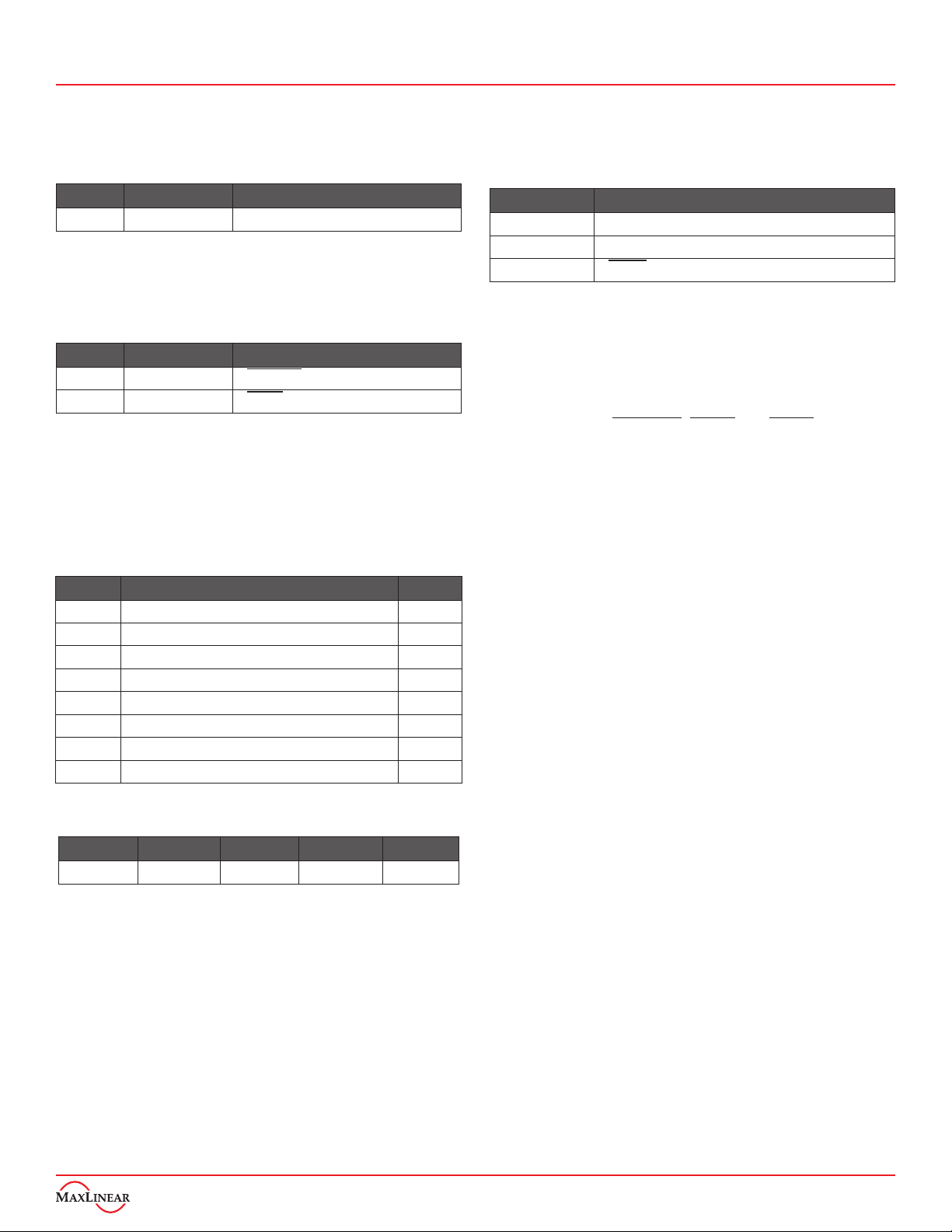
Jumpers are factory installed per Table 1. Jumper and
testing options are described in the next section.
Header Factory Setting Description
J2 Jumper 1-2 Connects VL to VCC
Table 1: Factory Settings
Connect J43 and J45 per Table 2 to configure the EVB for
normal mode operation.
Header Configuration Description
J43 Jumper 2-3 Shutdown = 1 enables normal mode
J45 Jumper 2-3 Online = 1 enables normal mode
Table 2: Normal Mode Configuration
Connect the RS232 drivers and receivers, TTL/CMOS
Driver Inputs and Receiver Outputs per Table 3 and power
and ground per Table 4 for immediate evaluation of the
XR32220 functionality and performance.
Header Connection Pin
J9 RS232 receiver input R1IN
J11 RS232 receiver input R2IN
J19 RS232 driver output T1OUT
J21 RS232 driver output T2OUT
J29 TTL / CMOS driver input T1IN
J27 TTL / CMOS driver input T2IN
J39 TTL / CMOS receiver output R1OUT
J37 TTL / CMOS receiver output R2OUT
Table 3: Input and Output Connections
J1 J1-1 J1-2 J1-3 J1-4
Name GND NC VCC VCC
NOTE:
1. VCC = 3.0V to 5.5V
Table 4: Power and Ground Connections
Pin J1-1 is the ground connection to the XR32220
evaluation board and is a common ground connection to the
entire board. An external 3.3V ±10% or 5.0V ±10% supply,
referenced to J1 pin 1 ground, should be connect to J1 pins
3 & 4.
Use probes summarized in Table 5 to observe operation at
various points. TP1 and TP2 provide GND for probes at 2
different spots.
Header Probe Points
J3, J4, J5, J7 C3, C4, C2 and C1 charge pump capacitors
J6 VCC into XR32220 transceiver
J42 Status output
Table 5: Monitoring Probes
Jumper and Testing Options
TTL / CMOS Logic Supply, VL - J2
The XR32220 has a separate logic supply pin, VL, which
controls the logic levels for the following pins: T1IN, T2IN,
R1OUT, R2OUT, Shutdown, Online and Status.
With a jumper placed across J2 the logic supply is tied to
VCC. To drive the VL logic supply to a lower voltage than
VCC, simply remove the jumper across J2 and connect
the separate external logic supply to pin 2 of J2. The logic
supply voltage, VL, must always be less than or equal to
VCC.
Power LED - J12
Connect Jumper J12 1-2 to illuminate the D1 LED when
power is connected if desired.
RS232 Receiver Inputs - J9 and J11 (J8 and J10)
Pin 2 on both the J9 and J11 connectors is the RS232
receiver input and pin 1 is ground. There is a 3 pin jumper
next to each of the test points, J8 and J10, to allow the
receiver inputs to be tied to VCC or ground if desired.
Normally the RS232 signal is applied to Pin 2 of J9 and J11
and J8 and J10 are unused.
RS232 Driver Outputs - J19 and J21 (J18 and J20)
Pin 2 on both the J19 and J21 connectors is the RS232
driver output and pin 1 is ground. There is a 2 pin jumper
next to each of these test points, J18 and J20, to allow for
any external loads to be applied if desired.
TTL/CMOS Driver Inputs - J27 and J29 (J26 and J28)
Pin 2 on both the J27 and J29 connectors is the TTL/CMOS
driver input and pin 1 is ground. There is a 3 pin jumper
next to each of the test points, J28 and J26 to allow the
driver inputs to be tied to VL or ground if desired. Normally
the signal generator would be applied to Pin 2 of J29 and/or
J27 and J28 and J26 would not be used.
TTL/CMOS Receiver Outputs - J37 and J39 (J36 and J38)
Pin 2 on both connectors is the TTL/CMOS receiver output
and pin 1 is ground. There is a 2 pin jumper next to each
of these test points, J38 and J36, to allow for any external
loads to be applied if desired.

XR32220 Evaluation Board User’s Manual
3/6
Control and Status Connections - J42, J44, and J46
The test points for Shutdown & Online (Auto On-Line) are
jumpers J44 and J46 respectively. These TTL/CMOS inputs
accept VL supply logic levels. Pin 2 on both connectors is
the input and pin 1 is ground. There is a 3 pin jumper next
to each of the test points, J45 and J43 to allow the control
inputs to be tied to VL or ground if desired.
J42 is connected to the Status pin for easy probing.
Paddle connection - R2
The XR32220 24pin QFN package has a paddle on the
underside. It is recommended that the paddle be connected
to ground on the PCB. The schematic of the evaluation
board pcb below shows this connection to ground. If it is
desired to remove the connection to ground, simply remove
R2.
Figure 3: XR32220 paddle connection to ground
1
2
3
4
5
7 8 9 10 11
13
14
15
16
17
2021222324
6
12
18
19
NC
NC
R1IN
R2IN
T1OUT
T2OUT
NC
NC
T2IN
T1IN
R2OUT
R1OUT
Status
Shutdown
Online
C1-
GND
VL
VCC
V+
C1+
C2+
C2-
V-
Figure 4: XR32220 Pin Configuration
Pin Configuration

XR32220 Evaluation Board User’s Manual
4/6
XR32220 EVB Schematic
Figure 5: XR32220-EVB Schematic

XR32220 Evaluation Board User’s Manual
5/6
Item Quantity Reference Part
1 7 C1, C2, C3, C4, C5, C8, C9 100nF_0805
2 1 C6 1uF_0805
3 1 C7 10uF_1210
4 1 D1 LED_160-1181-1-ND_0603
5 22 J2, J3, J4, J5, J6, J7, J9, J11, J12, J18, J19, J20, J21, J27,
J29, J36, J37, J38, J39, J42, J44, J46 Header 2
6 6 J8, J10, J26, J28, J43, J45 Header 3
7 1 J1 Header 4
8 1 L3 Inductor_BMB2A1000LN2_0805
9 1 R1 475ohm_0805
10 1R2 0ohm_0805
11 2TP1, TP2 Test point
12 1U1 XR32220 Sample
Table 4: Evaluation Board Bill of Material (BOM)
XR32220 EVB Bill of Material

XR32220 Evaluation Board User’s Manual
The content of this document is furnished for informational use only, is subject to change without notice, and should not be construed as a commitment by MaxLinear, Inc.. MaxLinear, Inc. assumes
no responsibility or liability for any errors or inaccuracies that may appear in the informational content contained in this guide. Complying with all applicable copyright laws is the responsibility of the
user. Without limiting the rights under copyright, no part of this document may be reproduced into, stored in, or introduced into a retrieval system, or transmitted in any form or by any means (electronic,
mechanical, photocopying, recording, or otherwise), or for any purpose, without the express written permission of MaxLinear, Inc.
Maxlinear, Inc. does not recommend the use of any of its products in life support applications where the failure or malfunction of the product can reasonably be expected to cause failure of the life support
system or to significantly affect its safety or effectiveness. Products are not authorized for use in such applications unless MaxLinear, Inc. receives, in writing, assurances to its satisfaction that: (a) the
risk of injury or damage has been minimized; (b) the user assumes all such risks; (c) potential liability of
MaxLinear, Inc. is adequately protected under the circumstances.
MaxLinear, Inc. may have patents, patent applications, trademarks, copyrights, or other intellectual property rights covering subject matter in this document. Except as expressly provided in any written
license agreement from MaxLinear, Inc., the furnishing of this document does not give you any license to these patents, trademarks, copyrights, or other intellectual property.
Company and product names may be registered trademarks or trademarks of the respective owners with which they are associated.
© 2017 MaxLinear, Inc. All rights reserved
XR32220 EVB Manual 6/6
Corporate Headquarters:
5966 La Place Court
Suite 100
Carlsbad, CA 92008
Tel.:+1 (760) 692-0711
Fax: +1 (760) 444-8598
www.maxlinear.com
High Performance Analog:
1060 Rincon Circle
San Jose, CA 95131
Tel.: +1 (669) 265-6100
Fax: +1 (669) 265-6101
Email: [email protected]
www.exar.com
Power Supply Recommendations
In order to ensure reliable operation at all data rates and
supply voltages, each supply should have at least 100nF
ceramic capacitor located as close to the supply terminals
(VL or Vcc) as possible. Additional 10uF and 100nF (C5
and C6) are recommended if the supply source is generated
from a linear power supply/regulator.
Layout Recommendations
1. Apply at least 100nF bypass capacitors as
close as possible to Vcc terminal and VL terminal
of transceiver.
2. Use at least two vias for Vcc/VL and GROUND
connections of bypass capacitors to minimize
effective via-inductance.
3. When possible, use Vcc and GROUND plane
to provide low-inductance traces and signal path.
Table of contents
Other MaxLinear Motherboard manuals

MaxLinear
MaxLinear MxL7225 User manual

MaxLinear
MaxLinear XR17V354 User manual

MaxLinear
MaxLinear MxL7225 User manual

MaxLinear
MaxLinear MxL7704 Series User manual

MaxLinear
MaxLinear XR31234 User manual

MaxLinear
MaxLinear MxL7213 User manual

MaxLinear
MaxLinear XR77XXEVB-XCM-V80 User manual

MaxLinear
MaxLinear MxL7218-EVK-2 User manual

MaxLinear
MaxLinear MxL7218 User manual