Maxon BIKEDRIVE User manual

USER MANUAL
Edition 2015-12
Document ID rel6003
not valid for «Limited Edition» (#1…250/250)

Contents
2maxon BIKEDRIVE | User Manual | rel6003
1Operation 3
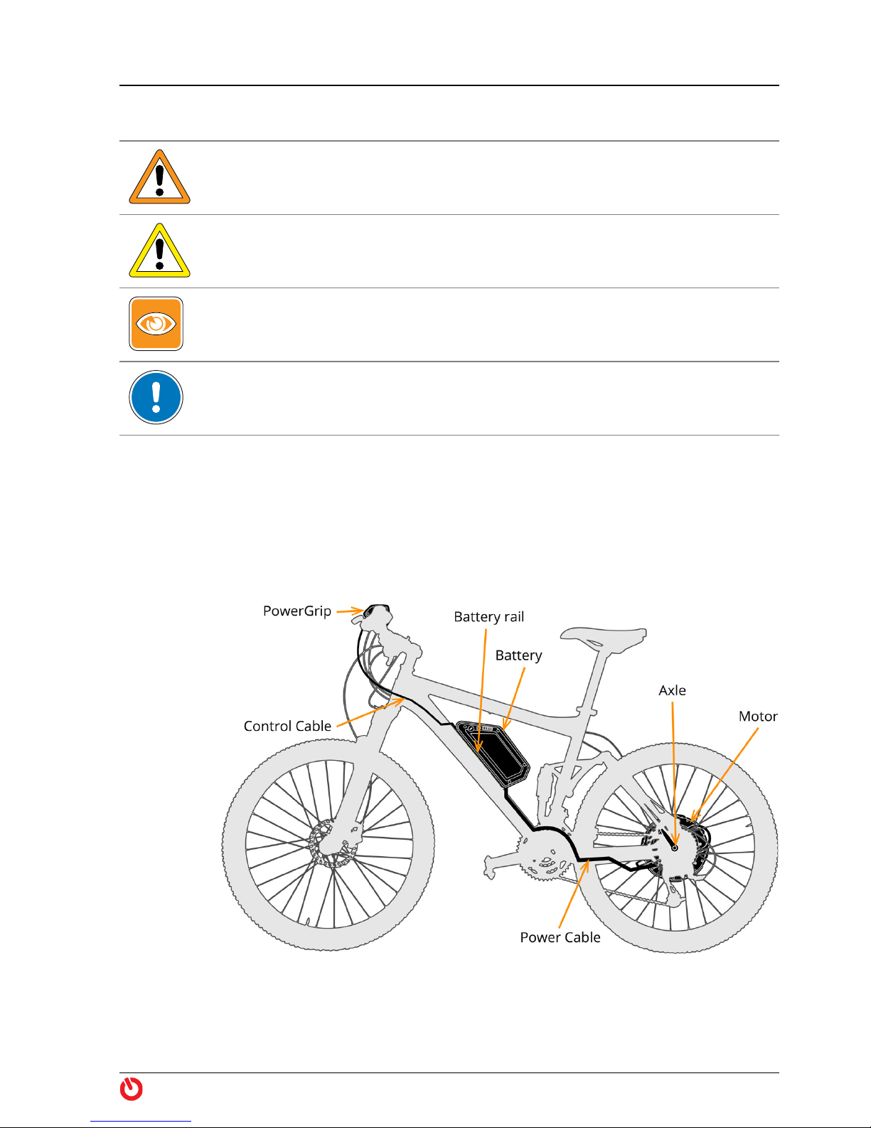
1.1 Components . . . . . . . . . . . . . . . . . . . . . . . . . . . . . . . . . . . . . . . . . . . . . . . . . . . .3
1.2 Legal Regulations . . . . . . . . . . . . . . . . . . . . . . . . . . . . . . . . . . . . . . . . . . . . . . . .4
1.3 Functional Principle . . . . . . . . . . . . . . . . . . . . . . . . . . . . . . . . . . . . . . . . . . . . . .4
1.4 Driving Modes . . . . . . . . . . . . . . . . . . . . . . . . . . . . . . . . . . . . . . . . . . . . . . . . . . .4
1.5 Handling. . . . . . . . . . . . . . . . . . . . . . . . . . . . . . . . . . . . . . . . . . . . . . . . . . . . . . . .5
1.5.1 PowerGrip . . . . . . . . . . . . . . . . . . . . . . . . . . . . . . . . . . . . . . . . . . . . . . .5
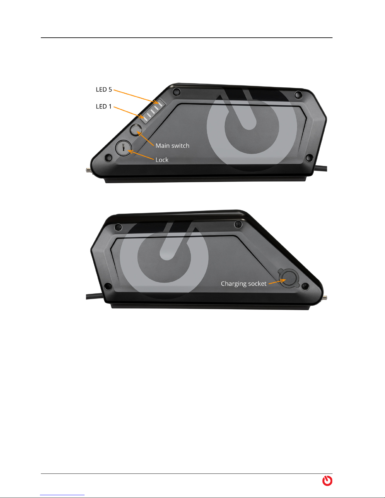
1.5.2 Battery . . . . . . . . . . . . . . . . . . . . . . . . . . . . . . . . . . . . . . . . . . . . . . . . . .6
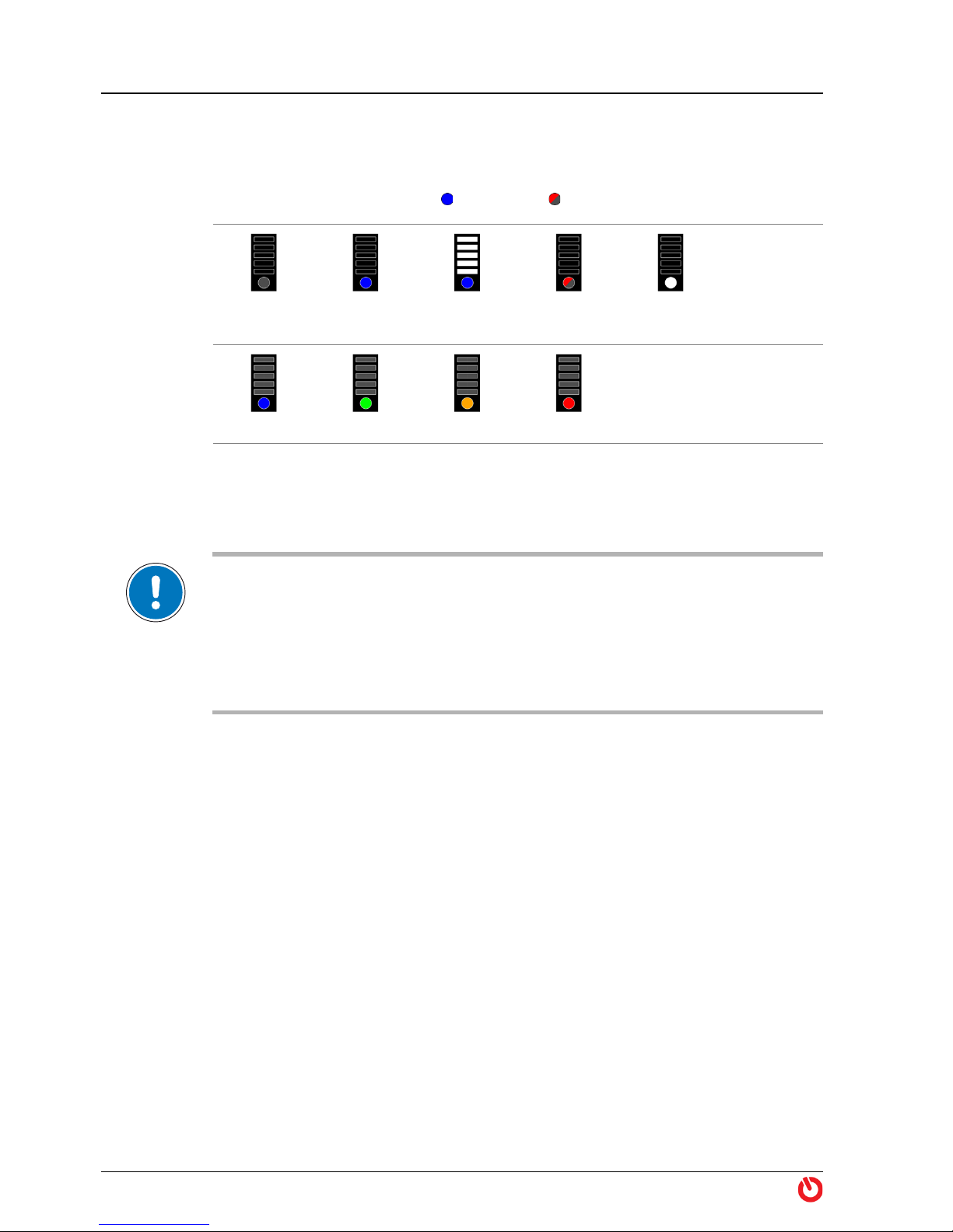
1.5.3 Displays . . . . . . . . . . . . . . . . . . . . . . . . . . . . . . . . . . . . . . . . . . . . . . . . .7
1.6 Before the Ride . . . . . . . . . . . . . . . . . . . . . . . . . . . . . . . . . . . . . . . . . . . . . . . . . .8
1.7 Riding the Bike . . . . . . . . . . . . . . . . . . . . . . . . . . . . . . . . . . . . . . . . . . . . . . . . . .9
1.7.1 Drive Performance . . . . . . . . . . . . . . . . . . . . . . . . . . . . . . . . . . . . . . . .9
1.7.2 Motor Power . . . . . . . . . . . . . . . . . . . . . . . . . . . . . . . . . . . . . . . . . . . . .9
1.7.3 Battery Capacity . . . . . . . . . . . . . . . . . . . . . . . . . . . . . . . . . . . . . . . . 10
1.8 After the Ride . . . . . . . . . . . . . . . . . . . . . . . . . . . . . . . . . . . . . . . . . . . . . . . . . 11
2Maintenance 13
2.1 Care & Maintenance. . . . . . . . . . . . . . . . . . . . . . . . . . . . . . . . . . . . . . . . . . . . 13
2.1.1 After each Ride . . . . . . . . . . . . . . . . . . . . . . . . . . . . . . . . . . . . . . . . . 13
2.1.2 Storage of the Battery . . . . . . . . . . . . . . . . . . . . . . . . . . . . . . . . . . . 14
2.1.3 Periodic Inspection . . . . . . . . . . . . . . . . . . . . . . . . . . . . . . . . . . . . . . 15
2.1.4 Replacing the rear Brake Disc . . . . . . . . . . . . . . . . . . . . . . . . . . . . . 15
2.1.5 Spare Parts. . . . . . . . . . . . . . . . . . . . . . . . . . . . . . . . . . . . . . . . . . . . . 21
2.2 Troubleshooting . . . . . . . . . . . . . . . . . . . . . . . . . . . . . . . . . . . . . . . . . . . . . . . 22
2.3 Disposal . . . . . . . . . . . . . . . . . . . . . . . . . . . . . . . . . . . . . . . . . . . . . . . . . . . . . . 23
3TechnicalData 25
WARNING!
RIDING AN ELECTRIC BIKE IS DANGEROUS!
ALWAYS USE EXTREME CAUTION WHEN USING THIS PRODUCT. MISUSE
OF THIS PRODUCT COULD RESULT IN SERIOUS INJURY OR DEATH. ONLY
USE THIS PRODUCT IF YOU ARE IN GOOD PHYSICAL HEALTH. NEVER ACT
IN A CARELESS MANNER WHEN USING THIS PRODUCT. YOU ARE
RESPONSIBLE FOR YOUR SAFETY AND THE SAFETY OF OTHERS AROUND
YOU WHEN USING THIS PRODUCT!
Contents

Operation
Components
maxon BIKEDRIVE | User Manual | rel6003 3
SYMBOLS USED
1OPERATION
1.1 Components
Figure 1 maxon BIKEDRIVE — Components
Indicates a potentially hazardous situation. Ignoring can cause serious
injury!
Indicates a possibly dangerous situation or draws attention to an unsafe
practice. Ignoring can cause injury or damage to components!
Indicates an important aspect. Ignoring can cause damage to components!
In illustrations, only the “eye” will be displayed.
Indicates an important aspect or gives important additional information.

Operation
Legal Regulations
4maxon BIKEDRIVE | User Manual | rel6003
1.2 Legal Regulations
Legislation
Inquire about the current legal requirements in your country or in your area before
putting your bike into operation.
Equipped with the BIKEDRIVE, the bike is a vehicle with motorized assistance.
Depending on the country, the vehicle is called E-Bike, Pedelec (Pedal Electric
Cycle), electric or motor-assisted bicycle, electro moped, autocycle, or similar,
and is subject to appropriate legal regulations.
Federal, State, and in some cases, city laws regulate aspects, such as, traffic
rules, permitted speed, type approval and homologation, compulsory insur-
ance, driving license, required equipment, etc.
1.3 Functional Principle
From a
standing
start in
action!
Additional power determined by the selected level from the BIKEDRIVE starts
as soon as you start pedaling. Upon reaching the maximum limited speed
(depending on your PowerGrip model), the motor automatically turns off.
You can switch off and re-activate the motorized assistance at any time. At
standstill, the motor can act as a pushing aid.
1.4 Driving Modes
Zero Motorized assistance is deactivated. You may switch to «Zero» at any time and
continue “normal cycling”. Thereby, the BIKEDRIVE behaves as if completely
switched off. It runs in internal freewheel and you will not even notice that it is
there.
Power1
Power2
Power3
You will be motor-assisted while pedaling. The torque applied by the drive will
be determined by the support level you have selected with the PowerGrip.
Boost While pedaling in the highest support level «Power3», you can continue turning
the PowerGrip to get extra performance and a torque of up to 50 Nm.
Pushing aid If you activate «Boost» at standstill, the motor will support you while pushing
the bike.

Operation
Handling
maxon BIKEDRIVE | User Manual | rel6003 5
1.5 Handling
A Word on
Safety
The BIKEDRIVE is extremely powerful! It possesses an extraordinarily high
degree of dynamics that will most likely surprise you at the beginning and it will
require some time to get used to.
Take it easy to start with and use caution on your first rides! Once you are set-
tled, you will experience the BIKEDRIVE to be total fun bearing a certain “addic-
tive potential”! ;-)
1.5.1 PowerGrip
Selecting the
driving mode
By rotating the PowerGrip you select the driving mode and, thereby, the degree
of motorized assistance (“Driving Mode” on page 7). You select the level using
four snap-in and one non-latching positions.
Each change of the selected support level is temporarily displayed by LEDs 1…5.
Following a support level change and while riding, the LEDs will show the
remaining battery level (“Charging Indicator” on page 7). The system status is
continuously displayed with LED A (“Status Indicator” on page 8).
Figure 2 PowerGrip
WARNING
Risk of injury
The BIKEDRIVE it extremely powerful and highly dynamic. Lack of habituation
to the high performance, handling, or operation can lead to serious injury!
• Be aware that the BIKEDRIVE will fundamentally change the driving behavior
of your bike — particularly in respect to aspects, such as, weight, weight distri-
bution, center of gravity, braking distance, braking response!
• Use extra caution during the “acclimatization phase” and select a low degree
of motorized assistance!
• Be aware that a changed setting at the PowerGrip will have an immediate
effect on the drive system, on speed, and on handling!

Operation
Handling
6maxon BIKEDRIVE | User Manual | rel6003
1.5.2 Battery
On the battery you will find the main switch, a lock, and displays for battery
charge and battery system status (page 7).
Figure 3 Battery BX360 ONE (left side)
Figure 4 Battery BX360 ONE (right side)
Power up To power up the BIKEDRIVE, press the main switch. During startup, all LEDs
light up. After reaching the operating condition «System ready», the LEDs will go
out for a moment. Subsequently, the charging level of the battery will be tem-
porarily displayed before the LED display will go off.
To display the battery charge level at anytime during your ride, press the main
switch.
Turn off To turn the BIKEDRIVE off, press the main switch until the LED display goes off.

Operation
Handling
maxon BIKEDRIVE | User Manual | rel6003 7
1.5.3 Displays
The PowerGrip features an LED display that will inform you about the currently
selected driving mode, the charging level of the battery, and the status of the
drive. A second LED display for the charging level is located at the battery.
Dimming To prevent glare, the brightness of the PowerGrip’s LED display will automati-
cally adapt to the ambient light.
Driving Mode
The selected support level is briefly displayed with each change. Thereafter, the
battery charge level is indicated.
Charging Indicator
The remaining capacity of the battery is displayed in 20% steps.
Zero
Neutral position — motorized assistance is turned off.
The PowerGrip engages in this position.
Power1 Turning towards you from the neutral position «Zero»
switches consecutively into levels «Power1», «Power2»,
and «Power3».
Turning away from you switches consecutively one level
back.
The PowerGrip engages in the selected position.
Power2
Power3
Boost
Turning towards you from the level «Power3» switches
to level «Boost».
The PowerGrip does not engage in this position and
bounces back to level «Power3» when released.
Charging
level
100…80% 80…60% 60…40% 40…20% 20…0%

Operation
Before the Ride
8maxon BIKEDRIVE | User Manual | rel6003
Status Indicator
The operating condition and motor temperature (in color graduation) is dis-
played.
The meaning, for example, is lights blue, flashes red.
1.6 Before the Ride
IMPORTANT!—Power up procedure
During power up procedure, the BIKEDRIVE will perform a self test and initialization.
Moving the bike contrary to the driving direction during this process can lead to mal-
function. Therefore, while power up procedure is in process,…
• do not rotate the rear wheel backwards (contrary to the driving direction),
• do not block the rear wheel,
• do not apply brakes!
1) Make sure that the battery is sufficiently charged for your planned
tour.
2) Make sure that the battery is turned off (page 6).
3) Slide battery into battery rail, let it click into place, and lock it. Remove
key.
4) Turn PowerGrip in neutral position «Zero».
5) Turn on main switch on battery.
6) After reaching the operation status «System ready» you are good to
go. Bear in mind the safety notes on page 5!
Operating
condition System
off
System
boot
System
ready
System
error
Master
halted
Motor
temperature
cold normal warm hot
“Riding the Bike” on
page 9

Operation
Riding the Bike
maxon BIKEDRIVE | User Manual | rel6003 9
1.7 Riding the Bike
1.7.1 Drive Performance
Figure 5 Slope vs. Weight/Support Level
The example in above graph reveals the following: A biker (weight 80 kg) with a
20 kg heavy 27½ inch bike can climb a 9% slope using support level «Power3»
without extra effort, just as on level terrain without any motorized assistance.
1.7.2 Motor Power
While riding, various system parameters are continuously monitored. As the
motor temperature reaches a certain limit, the motor automatically limits the
maximum output torque. You may of course continue cycling but you must
make do with reduced motorized assistance. The actual motor temperature will
be displayed via the PowerGrip’s multicolor LED A (“Status Indicator” on
page 8).
Motor warm Cause: This is no reason for concern! You are using the BIKEDRIVE for what it is
made for; motorized propulsion while pedaling.
What happens now? Just keep on going!
Depending on driving behavior, topography or usage of «Boost», heating of the
motor will possibly further increase and will, eventually, lead to the status indi-
cation «Motor hot».

Operation
Riding the Bike
10 maxon BIKEDRIVE | User Manual | rel6003
Motor hot Cause: You have pushed the BIKEDRIVE to the maximal permitted motor tem-
perature.
What happens now? Just keep on going!
The motor will automatically regulate to the highest possible torque output
without exceeding the maximum permitted motor temperature.
You can continue to use all support levels and you will be assisted by the motor
whereby, depending on the load, full torque will temporarily not be available in
«Boost» mode. The more you relieve the motor thus permitting it to cool down,
the sooner you can expect «Boost» and to return to reach full torque.
1.7.3 Battery Capacity
Among other factors, the operating range per battery charge also depends on
the following influencing factors.
How to get
the most out
of a battery
charge
• Gross weight and rolling friction: For example, additionally carried
weight, trailer, low tire pressure, grazing brakes, worn components,
headwind.
• Topography
• Ambient temperature: By principle, the battery can only deliver its
maximum capacity within given temperature limits (Table 4 on
page 27).
• Support level/start-up/acceleration/changing gears: The more you
make use of motorized assistance (thus especially at start-up, during
acceleration, and when climbing a hill), the less your distance and
operating range will be.
Use the gears as with a “normal” bike. Thereby, shift early into a lower
gear when climbing a hill.
Running
empty
You may fully discharge the battery. The internal controller ensures that the
battery does not suffer damage.
Shutdown The BIKEDRIVE switches off completely after approximately 30 minutes without
power output. To recommence the motorized ride, restart the BIKEDRIVE
(“Before the Ride” on page 8).

Operation
After the Ride
maxon BIKEDRIVE | User Manual | rel6003 11
1.8 After the Ride
If you take a
break:
Always turn the BIKEDRIVE completely off whenever you are not sitting on the
bike and protect it against theft or tampering!
1) Turn the PowerGrip in neutral position «Zero».
2) Turn the BIKEDRIVE off.
After the fun
is before the
fun!
Perform the following steps to be ready for the next ride. This will keep your
maxon BIKEDRIVE ready to deliver fun and adrenalin rushes for many years:
1) Turn the PowerGrip in neutral position «Zero».
2) Turn the BIKEDRIVE off.
3) Clean the bike (page 13).
4) Remove the battery.
5) Remove moisture from motor, PowerGrip, battery, battery rail, and
cables, if any.
6) Charge the battery (page 13)
7) Observe the instructions on battery storage (page 14).
Prepare for
transport:
1) Remove the battery and cover the battery rail to protect it from dirt
and humidity.
2) Protect the bike from dirt, dust, rain, snow, salt water, spray water. If
necessary, use transport bag or cover with tarpaulin.
3) Observe the bike manufacturer’s instructions if you intend to remove
the front and/or rear wheel for transport.
4) Observe the following remark on air transportation if you intend to
take your bike along on a flight.
Transport by Air
According to the International Air Transport Association (IATA), lithium batteries with
a capacity exceeding 100 Wh are considered as hazardous goods subject to appro-
priate conditions for air transport. Carriage on board passenger aircraft is not per-
mitted.
Note that all BIKEDRIVE batteries have a capacity of more than 100 Wh.
Check with your airline or your travel agent on means of transportation
before scheduling a flight.

Operation
After the Ride
12 maxon BIKEDRIVE | User Manual | rel6003
••page intentionally left blank••

Maintenance
Care & Maintenance
maxon BIKEDRIVE | User Manual | rel6003 13
2MAINTENANCE
The BIKEDRIVE is designed for a demanding off-road use and is extremely
sturdy. Nevertheless, please contact your authorized BIKEDRIVE dealer if any
malfunction should occur.
Please note: You are not entitled to perform any repair on the BIKEDRIVE. It
does not contain any user-serviceable parts.
After appropriate instruction by the specialized dealer you are permitted to
carry out the following described cleaning, inspection, and maintenance work.
Thereby, keep strictly to the instructions and be aware: A manipulation of the
bike that is equipped with a BIKEDRIVE carries a certain danger of getting
injured. Careless or irresponsible behavior or failure to follow the precaution-
ary measures can cause the drive to start.
2.1 Care & Maintenance
2.1.1 After each Ride
Cleaning with Water
Do not expose motor and battery to direct water spray!
1) Clean bike: Remove soiling using a damp rag.
2) Remove moisture: Rub dry motor, battery, cables, and plug connec-
tors with a soft cloth.
WARNING
Risk of injury
Work on the bike can lead to serious injury!
Turn off the BIKEDRIVE and remove the battery before you commence with any
work, such as cleaning, maintenance, or troubleshooting!
WARNING
Risk of injury
You must no longer use visibly damaged batteries. Continued use can lead to
serious injury!
• Remove the damaged battery from the battery rail!
• Do not connect the damaged battery to the battery charger!
• Discard the damaged battery in no case with normal household waste but
only to the appropriate official collection site or via your specialized dealer!

Maintenance
Care & Maintenance
14 maxon BIKEDRIVE | User Manual | rel6003
3) Check for damage: Check motor, battery, cables, and plug connectors
for external damage. Let your authorized BIKEDRIVE dealer replace
any damaged part immediately.
4) Charge battery:
a) Connect battery charger with battery.
b) Connect battery charger to power outlet (100…240 VAC, 50…60 Hz)
and switch on.
The start of the charging process is indicated by a green battery
charger LED in combination with all white battery LEDs.
During the charging process, an amber battery charger LED and,
according to the charging level, the white battery LEDs light up.
Full battery load is indicated by a green battery charger LED and
the switched off battery.
If no battery is connected to the battery charger, a red battery char-
ger LED will light up.
c) Disconnect battery from battery charger.
d) Disconnect battery charger from power plug.
5) Store battery in a cool dry place. For example, do not let the battery
in your car when it is exposed to direct sunlight since it can get
extremely hot in a very short time! Also, observe the permitted envi-
ronmental conditions (page 27)!
2.1.2 Storage of the Battery
Store the battery in a cool, dry place. For information on the maximum permit-
ted storage temperature see Table 4 on page 27.
Long-term
storage
If you are not using the battery for extended periods, store it at approximately
60% of its capacity. A permanently higher charge will accelerate the principle-
related natural aging of the battery.
WARNING
Risk of injury
Wrong charging current or penetrating humidity can damage the battery and
can lead to serious injury!
• Use only an original BIKEDRIVE battery charger to recharge the battery!
• During the charging process, protect the battery, battery charger, and plug
connectors from contact with humidity (water, dew, cleaning agents, etc.) and
observe the permitted environmental conditions (
section “3 Technical Data”
on page 25)!
• Do not carry out any cleaning or maintenance on the bike while charging is
ongoing!
• Do not leave charger and battery unattended during the charging process!

Maintenance
Care & Maintenance
maxon BIKEDRIVE | User Manual | rel6003 15
2.1.3 Periodic Inspection
In addition to the maintenance specified by the bike manufacturer, you or your
authorized BIKEDRIVE dealer must perform the following inspections.
Table 1 Maintenance Plan
2.1.4 Replacing the rear Brake Disc
2.1.4.1 Dismantling
When? What?
After heavy use Brakes: Check wear on brake discs and brake pads,
replace if necessary
Every 200 km
or
at least annually
•Rear wheel: Check on specified spoke tension
•Quick-release axle: Check on specified torque
•Screw connections: Check for firm fit
•Plug connections: Check for firm fit
Every 1000 km
or
at least annually
Battery rail: Check for firm fit
Every 6 months
Battery: Fully recharge the battery and disconnect
from battery charger. Then discharge to
approximately 60%.
IMPORTANT!
During disassembly, exposed parts can easily be damaged. Exercise caution.
Remove
cover
1) Disconnect motor plug from
Power Cable.
2) Dismantle rear wheel.
3) Loosen and remove screws
(A).
4) Carefully pull off cover (B).

Maintenance
Care & Maintenance
16 maxon BIKEDRIVE | User Manual | rel6003
Fold down
cable
Loosen
set screw
5) Carefully fold down cable (C)
by approx. 90°.
6) Loosen set screw (D) about 3
turns (do not remove!).
Remove
torque lever
IMPORTANT!
Do not damage cable.
7) Carefully pull off torque
lever (E) in axial direction
from hub by slightly weigh-
ing back and forth. Put over
cable and plug and remove.
Remove
brake disc
8) Loosen and remove screws
(H).
9) Remove spacer plate (G).
10) Carefully pull off brake disc.

Maintenance
Care & Maintenance
maxon BIKEDRIVE | User Manual | rel6003 17
2.1.4.2 Reassembly
IMPORTANT!
• During reassembly, parts can easily be damaged. Exercise caution.
• To attach the brake disc, use only the maxon «Brake Screw Kit TX25»
(519904), the originally used, or as to below specified screws.
• The screws must not axially touch the bottom of the tap. Wrong or too long
screws lead to permanent damage of the motor.
Use «Brake
Screw Kit
TX25»
or
check
dimensions
RECOMMENDATION:
Use maxon’s «Brake Screw Kit
TX25» (upper illustration).
If you decide not to use the
maxon screw kit:
Make sure that fastening screws
and washers correspond with
the indicated dimensions
(lower illustration)!
Mount
brake disc
1) Check brake disc and hub for
cleanness, clean if necessary.
2) Observe specified brake
disc’s sense of rotation.
3) Slide brake disc (F) on hub,
align radially.
4) Mount spacer plate (G).
5) Mount screws (H) from
«Brake Screw Kit TX25» (for
others, apply medium
strength threadlocker first),
lightly tighten by hand.
6) Turn brake disc against direc-
tion of travel until it strikes
against screws.
7) Tighten screws crosswise
(torque 7 Nm).

Maintenance
Care & Maintenance
18 maxon BIKEDRIVE | User Manual | rel6003
Mount
torque lever
8) Align cable cutouts of torque
lever (E) and hub.
IMPORTANT!
Do not damage cable.
9) Carefully put torque lever in
axial direction over cable
and plug, slide onto hub.
Mount
set screw
Fold up cable
10) Radially align torque lever.
11) Carefully tighten set screw
(D). Do not apply thread-
locker!
12) Carefully fold up cable (C) by
approx. 90° and insert into
groove.
Mount cover
13) Place cover (B) on torque
lever and align.
IMPORTANT!
The cable must entirely rest in
the groove. It must not protrude
nor be pinched in the separating
pane.
14) Mount screws (A) and lightly
tighten.
15) Check cover for correct fit.
16) Tighten screws crosswise
until parts fully contact.

Maintenance
Care & Maintenance
maxon BIKEDRIVE | User Manual | rel6003 19
Install rear
wheel
17) Rotate rear wheel until
torque lever points in direc-
tion of travel.
IMPORTANT!
Do not damage cable.
18) Carefully position rear wheel
in dropout ans mount as fol-
lows:
QR
• Lead axle from left through
the motor’s hollow shaft.
• Align rear wheel, hold tension
nut, and slightly tighten axle.
E-Thru
• Insert tension nut in right
dropout.
• Insert axle from left through
the motor’s hollow shaft.
• Align rear wheel, slightly
tighten axle.
Maxle / X-12
• Screw tension nut in right
dropout, tighten by hand until
stop.
• Insert axle from left through
the motor’s hollow shaft.
• Align rear wheel, slightly
tighten axle.
Mount stop-
per sleeve
19) Turn motor against direction
of travel until torque lever
strikes against frame from
below.
20) Tighten axle.

Maintenance
Care & Maintenance
20 maxon BIKEDRIVE | User Manual | rel6003
Check
settings
21) Check settings on derailleur
and rear wheel brake pads,
adjust if necessary.
22) Plug Power Cable to motor
plug and lock with bayonet
coupling.
23) Make sure that spring travel
are not restricted by the
cable.
24) Fasten Power Cable (but not
the motor plug!) to the
frame using cable ties.
25) Fasten motor cable to the
frame using «Power Cable
Strip».
Other manuals for BIKEDRIVE
3
Table of contents
Other Maxon Bicycle Accessories manuals