Maxon IDX 56 User manual

Table of Contents
IDX 56 User Manual
A-2 mmag | 2020-04 | rel9398
1 ABOUT 5
1.1 About this Document. . . . . . . . . . . . . . . . . . . . . . . . . . . . . . . . . . . . . . . . . . . . . . . 5
1.2 About the Devices. . . . . . . . . . . . . . . . . . . . . . . . . . . . . . . . . . . . . . . . . . . . . . . . . 8
1.3 About the Safety Precautions . . . . . . . . . . . . . . . . . . . . . . . . . . . . . . . . . . . . . . . 10
2 SPECIFICATIONS 13
2.1 Technical Data . . . . . . . . . . . . . . . . . . . . . . . . . . . . . . . . . . . . . . . . . . . . . . . . . . 13
2.2 Limitations of the Electronics . . . . . . . . . . . . . . . . . . . . . . . . . . . . . . . . . . . . . . . 17
2.3 Dimensional Drawings . . . . . . . . . . . . . . . . . . . . . . . . . . . . . . . . . . . . . . . . . . . . 17
2.4 Nameplate. . . . . . . . . . . . . . . . . . . . . . . . . . . . . . . . . . . . . . . . . . . . . . . . . . . . . . 18
2.5 Identification Keys. . . . . . . . . . . . . . . . . . . . . . . . . . . . . . . . . . . . . . . . . . . . . . . . 18
2.6 Standards . . . . . . . . . . . . . . . . . . . . . . . . . . . . . . . . . . . . . . . . . . . . . . . . . . . . . . 19
3 MECHANICAL INSTALLATION 21
3.1 General Rules . . . . . . . . . . . . . . . . . . . . . . . . . . . . . . . . . . . . . . . . . . . . . . . . . . . 21
3.2 Mounting Position . . . . . . . . . . . . . . . . . . . . . . . . . . . . . . . . . . . . . . . . . . . . . . . . 21
3.3 Fixation . . . . . . . . . . . . . . . . . . . . . . . . . . . . . . . . . . . . . . . . . . . . . . . . . . . . . . . . 22
3.4 Alignment and Coupling . . . . . . . . . . . . . . . . . . . . . . . . . . . . . . . . . . . . . . . . . . . 22
4 ELECTRICAL INSTALLATION 23
4.1 General Rules . . . . . . . . . . . . . . . . . . . . . . . . . . . . . . . . . . . . . . . . . . . . . . . . . . . 23
4.2 Cabling . . . . . . . . . . . . . . . . . . . . . . . . . . . . . . . . . . . . . . . . . . . . . . . . . . . . . . . . 24
4.3 Connections . . . . . . . . . . . . . . . . . . . . . . . . . . . . . . . . . . . . . . . . . . . . . . . . . . . . 26
4.3.1 CAN IN (X1) . . . . . . . . . . . . . . . . . . . . . . . . . . . . . . . . . . . . . . . . . . . . . . . . . . . . . . . . . . . . 27
4.3.2 CAN OUT (X2) . . . . . . . . . . . . . . . . . . . . . . . . . . . . . . . . . . . . . . . . . . . . . . . . . . . . . . . . . . 28
4.3.3 EtherCAT IN (X1) and EtherCAT OUT (X2) . . . . . . . . . . . . . . . . . . . . . . . . . . . . . . . . . . . . 29
TABLE OF CONTENTS
READ THIS FIRST
THESE INSTRUCTIONS ARE INTENDED FOR QUALIFIED TECHNICAL PERSONNEL. PRIOR COMMENCING WITH
ANY ACTIVITIES…
• you must carefully read and understand this manual and
• you must follow the instructions given therein.
THE IDX 56 DRIVE IS CONSIDERED AS PARTLY COMPLETED MACHINERY ACCORDING TO EU DIRECTIVE 2006/
42/EC, ARTICLE 2, CLAUSE (G) AND IS INTENDED TO BE INCORPORATED INTO OR ASSEMBLED WITH OTHER
MACHINERY OR OTHER PARTLY COMPLETED MACHINERY OR EQUIPMENT.
THEREFORE, YOU MUST NOT PUT THE DEVICE INTO SERVICE,…
• unless you have made completely sure that the other machinery fully complies with the EU directive’s requirements!
• unless the other machinery fulfills all relevant health and safety aspects!
• unless all respective interfaces have been established and fulfill the herein stated requirements!

Table of Contents
IDX 56 User Manual
mmag | 2020-04 | rel9398 A-3
4.3.4 I/O (X3) . . . . . . . . . . . . . . . . . . . . . . . . . . . . . . . . . . . . . . . . . . . . . . . . . . . . . . . . . . . . . . . . 30
4.3.5 Supply (X4) . . . . . . . . . . . . . . . . . . . . . . . . . . . . . . . . . . . . . . . . . . . . . . . . . . . . . . . . . . . . . 34
4.3.6 USB (X5) . . . . . . . . . . . . . . . . . . . . . . . . . . . . . . . . . . . . . . . . . . . . . . . . . . . . . . . . . . . . . . . 37
4.4 Status Indicators . . . . . . . . . . . . . . . . . . . . . . . . . . . . . . . . . . . . . . . . . . . . . . . . 39
4.5 Wiring Diagrams . . . . . . . . . . . . . . . . . . . . . . . . . . . . . . . . . . . . . . . . . . . . . . . . 42
5 COMMISSIONING 45
5.1 General Rules . . . . . . . . . . . . . . . . . . . . . . . . . . . . . . . . . . . . . . . . . . . . . . . . . . 45
5.2 Final Checks prior Commissioning . . . . . . . . . . . . . . . . . . . . . . . . . . . . . . . . . . 46
5.3 Parameterization and Programming . . . . . . . . . . . . . . . . . . . . . . . . . . . . . . . . . 46
6 MAINTENANCE 47
6.1 General Rules . . . . . . . . . . . . . . . . . . . . . . . . . . . . . . . . . . . . . . . . . . . . . . . . . . 47
6.2 Periodic Inspection . . . . . . . . . . . . . . . . . . . . . . . . . . . . . . . . . . . . . . . . . . . . . . 47
6.3 Long-term Storage. . . . . . . . . . . . . . . . . . . . . . . . . . . . . . . . . . . . . . . . . . . . . . . 48
6.4 Decommissioning . . . . . . . . . . . . . . . . . . . . . . . . . . . . . . . . . . . . . . . . . . . . . . . 48
6.5 Disposal . . . . . . . . . . . . . . . . . . . . . . . . . . . . . . . . . . . . . . . . . . . . . . . . . . . . . . . 48
LIST OF FIGURES 49
LIST OF TABLES 50
INDEX 51

Table of Contents
IDX 56 User Manual
A-4 mmag | 2020-04 | rel9398
••page intentionally left blank••

About
About this Document
IDX 56 User Manual
mmag | 2020-04 | rel9398 1-5
1 ABOUT
The «IDX drive» must be installed in a particular and specific way. Therefore, closely follow the described
information in given order to achieve both safe and easy installation as well as reliable operational service.
The easiest and safest way of doing
• Do not engage with any task unless you have the knowledge to do so.
• Make sure that you have read and understood the safety precautions. Observe them, keep them in mind,
and follow them at all times.
• Follow the description in given order. Work your way through the document. Do not skip nor cut short any
sections.
• Read the «General Rules» at the beginning of a chapter closely. Observe them, keep them in mind, and
follow them at all times.
1.1 About this Document
1.1.1 Intended Purpose
Use the docu-
ment to…
–stay safe,
–be fast,
–end up with set
up and ready-to-
go equipment.
The purpose of the present document is to familiarize you with the IDX drive. It will highlight the tasks for
safe and adequate installation and commissioning. Follow the described instructions …
• to avoid dangerous situations,
• to keep installation and/or commissioning time at a minimum,
• to increase reliability and service life of the described equipment.
The present document is part of a documentation set and contains performance data and specifications,
information on fulfilled standards, details on connections and pin assignment, and wiring examples. The
below overview shows the documentation hierarchy and the interrelationship of its individual parts:
Figure 1-1 Documentation structure

About
About this Document
IDX 56 User Manual
1-6 mmag | 2020-04 | rel9398
1.1.2 Target Audience
The present document is intended for trained and skilled personnel. It conveys information on how to under-
stand and fulfill the respective work and duties.
1.1.3 How to use
Throughout the document, the following notations and codes will be used.
Table 1-1 Notation used
1.1.4 Symbols and Signs
In the course of the present document, the following symbols and signs will be used.
Table 1-2 Symbols and signs
Notation Meaning
(n) refers to an item (such as part numbers, list items, etc.)
denotes “see”, “see also”, “take note of” or “go to”
Type Symbol Meaning
Safety alert
(typical)
DANGER Indicates an imminent hazardous situation. If not
avoided, it will result in death or serious injury.
WARNING Indicates a potential hazardous situation. If not
avoided, it can result in death or serious injury.
CAUTION
Indicates a probable hazardous situation or calls the
attention to unsafe practices. If not avoided, it may
result in injury.
Prohibited
action
(typical)
Indicates a dangerous action. Hence, you must not!
Mandatory
action
(typical)
Indicates a mandatory action. Hence, you must!
Information
Requirement /
Note / Remark
Indicates an activity you must perform prior continuing,
or gives information on a particular item you need to
observe.
Best practice Indicates an advice or recommendation on the easiest
and best way to further proceed.
Material
damage
Indicates information particular to possible damage of
the equipment.

About
About this Document
IDX 56 User Manual
mmag | 2020-04 | rel9398 1-7
1.1.5 Trademarks and Brand Names
For easier legibility, registered brand names are listed below and will not be further tagged with their respec-
tive trademark. It must be understood that the brands (the list below is not necessarily concluding) are pro-
tected by copyright and/or other intellectual property rights even if their legal trademarks are omitted in the
later course of this document.
Table 1-3 Brand names and trademark owners
1.1.6 Copyright
This document is protected by copyright. Any further use (including reproduction, translation, microfilming,
and other means of electronic data processing) without prior written approval is not permitted. The men-
tioned trademarks belong to their respective owners and are protected under intellectual property rights.
© 2020 maxon. All rights reserved. Subject to change without prior notice.
mmag | IDX 56 User Manual | Edition 2020-04 | DocID rel9398
Brand name Trademark owner
Adobe® Reader® © Adobe Systems Incorporated, USA-San Jose, CA
CANopen®
CiA® © CiA CAN in Automation e.V, DE-Nuremberg
EtherCAT® © EtherCAT Technology Group, DE-Nuremberg, licensed by Beckhoff Automation
GmbH, DE-Verl
Loctite® © Henkel AG & Co. KGaA, DE-Düsseldorf
NORD-LOCK® © Nord-Lock International AB, SE-Malmö
maxon motor ag
Brünigstrasse 220
CH-6072 Sachseln
+41 41 666 15 00
www.maxongroup.com

About
About the Devices
IDX 56 User Manual
1-8 mmag | 2020-04 | rel9398
1.2 About the Devices
Capabilities of the
device, included
features.
maxon's «IDX 56» are compact, high-performance, IP 65-protected, brushless DC drives with either inte-
grated positioning controller or speed controller particularly suitable for the use in harsh environmental con-
ditions. They deliver up to 0.7 Nm of continuous torque and come in a wide range of configurable options
that allow full adaption to suit specific needs.
The IDX drives are designed to be commanded and controlled as a slave node in a CANopen or EtherCAT
network. They fully integrate into the maxon EPOS4 environment and possess outstanding position control
and speed control capabilities. Latest technology, such as field-oriented control (FOC), acceleration/velocity
feed forward in combination with highest control cycle rates and a broad range of other functionalities allow
sophisticated, ease-of-use motion or speed control. The IDX drives are available in different lengths and
various winding versions:
•IDX 56 Drive with Positioning Controller
56 mm square drive with integrated positioning controller and CANopen or EtherCAT interface
•IDX 56 Drive with Speed Controller
56 mm square drive with integrated servo controller, I/O-commanded
The IDX drives come with an optionally available holding break which blocks the rotor while the drive is in
switched off state. Thereby, the break is designed as a holding brake during standstill and not as brake suit-
able for continual deceleration purposes.
For detailed information on the full range of functions, features, and usable modes, consult the additionally
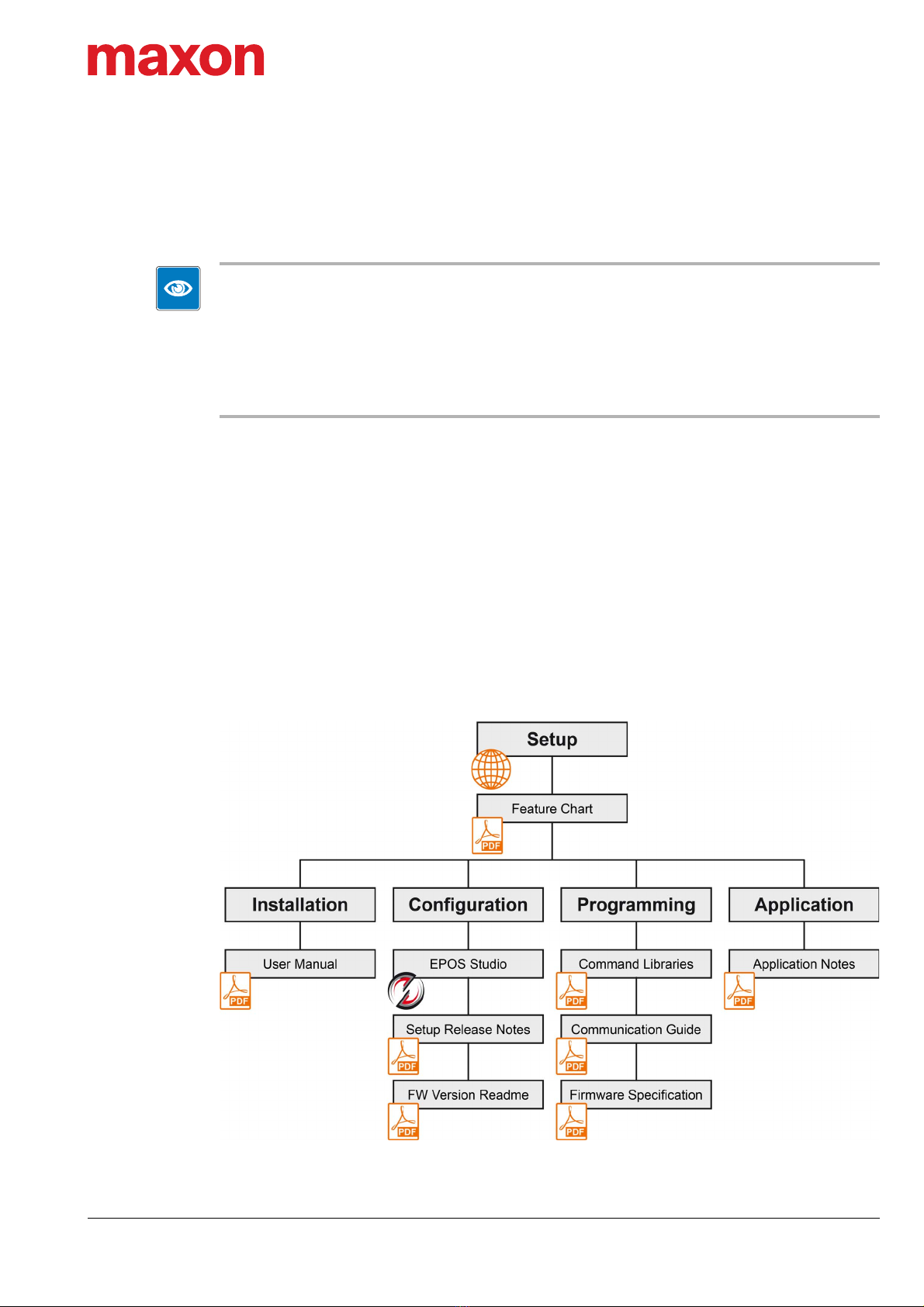
available document «IDX 56 Feature Chart».
The IDX drives are especially designed to suit high demands, such as in…
• Robotics
• Handling devices
• Equipment engineering
• Automation
• Special-purpose machinery engineering
• or similar products
The IDX drives may only be used as components in electrical equipment or machinery and may only be
commissioned as an integrated part of such equipment or machinery. Any other use is not permitted.
The IDX drives must be operated only within the limits specified in the present document.
For easier legibility, in the later course of this document naming of components will be as follows:
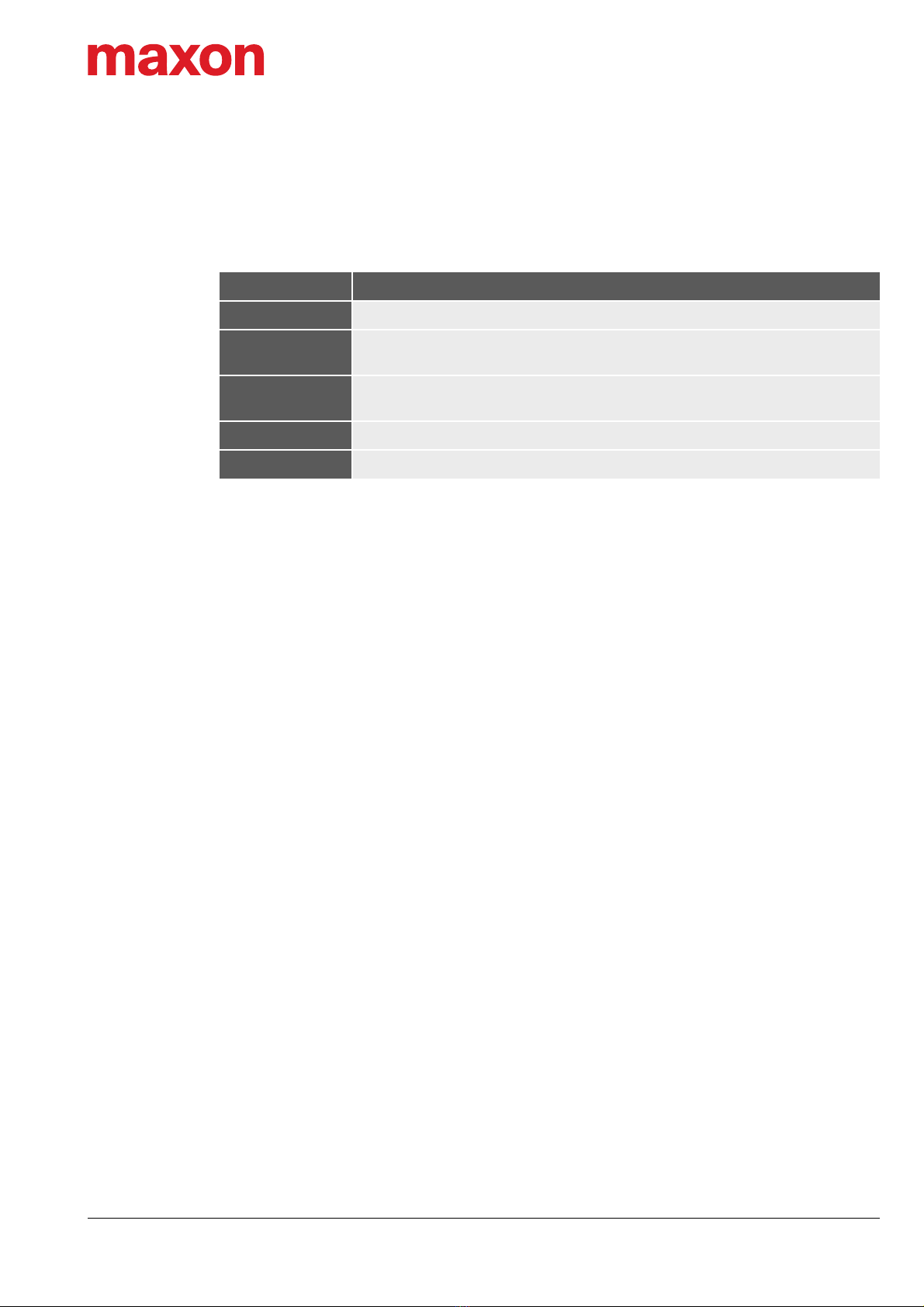
Table 1-4 Abbreviations
Short form Meaning
EPOS4 hardware and/or firmware functionalities based on maxon EPOS4 platform
IDX any type of IDX drive
IDX 56 any type of IDX 56 drive
IDX 56 CANopen IDX drive with positioning controller and CANopen interface
IDX 56 EtherCAT IDX drive with positioning controller and EtherCAT interface
IDX 56 I/O IDX drive with speed controller and I/O interface

About
About the Devices
IDX 56 User Manual
mmag | 2020-04 | rel9398 1-9
SOURCES FOR ADDITIONAL INFORMATION
Find the latest edition of the present document
and other information on IDX here:
http://idx.maxongroup.com/
Find the latest information on the EPOS4 platform
here:
http://epos.maxongroup.com/
In addition, you may wish to browse the EPOS
video library. It features video tutorials that pro-
vide easy to follow instructions on how to get
started with «EPOS Studio» and shows you tips
and tricks on how to setup communication inter-
faces, and so on. Explore on Vimeo:
https://vimeo.com/album/4646388/
If you should encounter any problems or if you
have any questions, feel free to contact the
maxon Support Center:
https://support.maxongroup.com/hc/en-us/

About
About the Safety Precautions
IDX 56 User Manual
1-10 mmag | 2020-04 | rel9398
1.3 About the Safety Precautions
Keep in mind:
Safety first! • Make sure that you have read and understood the note “READ THIS FIRST” on page A-2.
• Do not engage with any work unless you possess the stated skills (chapter “1.1.2 Target Audi-
ence” on page 1-6).
• Refer to chapter “1.1.4 Symbols and Signs” on page 1-6 to understand the subsequently used
indicators.
• Make sure that you observe any regulation with regard to health, safety, and accident prevention as
well as to environmental protection applicable in your country and at the site of implementation.
• Make sure to read and understand the «General Rules» at the beginning of a chapter closely.
Observe them, keep them in mind, and follow them at all times.
DANGER
High voltage and/or electrical shock
Touching live wires causes death or serious injuries!
• Consider any power cable as connected to live power, unless having proven the opposite!
• Make sure that neither end of cable is connected to live power!
• Make sure that power source cannot be engaged while work is in process!
• Obey lock-out/tag-out procedures!
• Make sure to securely lock any power engaging equipment against unintentional engagement and tag
it with your name!
WARNING
Draw in/pull in/entanglement hazard
Rotating shaft and drive elements attached to it can cause serious injuries!
• Stay clear of the drive’s driven end and do not touch while in operation.
• Keep clothes and other objects away from the drive’s driven end and make sure that no loose objects
can entangle or be drawn-in with any rotating part.
WARNING
Burst or break hazard
Ejected or slung away parts can cause serious injuries!
• Make sure that the produced centrifugal force at the drive’s driven end cannot cause any part to
become lose.
• Install suitable safety guards to protect the vicinity around the drive’s driven end from possibly ejected
or slung away parts or components.
CAUTION
Risk of burns and scaling
Touching hot surfaces may cause serious injuries!
• Do not touch the drive during operation or shortly thereafter.
• Allow the drive to cool down and test the temperature before you touch the casing.

About
About the Safety Precautions
IDX 56 User Manual
mmag | 2020-04 | rel9398 1-11
Requirements
• Make sure that all associated devices and components are installed according to local regulations.
• Be aware that, by principle, an electronic apparatus can not be considered fail-safe. Therefore, you must
make sure that any machine/apparatus has been fitted with independent monitoring and safety equip-
ment. If the machine/apparatus should break down, if it is operated incorrectly, if the control unit breaks
down or if the cables break or get disconnected, etc., the complete drive system must return – and be
kept – in a safe operating mode.
• Be aware that you are not entitled to perform any repair on components supplied by maxon.
Electrostatic sensitive device (ESD)
• Wear working cloth and use equipment in compliance with ESD protective measures.
• Handle device with extra care.

About
About the Safety Precautions
IDX 56 User Manual
1-12 mmag | 2020-04 | rel9398
••page intentionally left blank••

Specifications
Technical Data
IDX 56 User Manual
mmag | 2020-04 | rel9398 2-13
2 SPECIFICATIONS
2.1 Technical Data
Parameter Unit
IDX 56 M IDX 56 L
24 V 48 V 24 V 48 V
Drive data
Nominal power supply voltage [a] VDC 24 48 24 48
Nominal speed [a] rpm 4'500 4'500 2'750 3'500
Nominal torque (max. continuous
torque) mNm 424 [b]
376 [a]
516 [b]
458 [a]
794 [b]
704 [a]
778 [b]
690 [a]
Recommended speed control range —From standstill up to nominal speed
Maximum permissible drive speed rpm 6'000 6'000 6'000 5'000
Maximum torque (short-time) mNm 888
(<10 s)
1'498
(<10 s)
1'596
(<10 s)
1'997
(<10 s)
Nominal efficiency (without options) %84 87 85 87
Electrical
rating
Nominal supply voltage VCC [c] VDC 12…48
Logic supply voltage +VCVDC 12…48
Absolute supply voltage +Vmin / +Vmax VDC 10 / 60
Pulse width modulation frequency kHz 50
Sampling rate PI current controller kHz 25 (40 μs)
Sampling rate PI speed controller kHz 2.5 (400 μs)
Sampling rate PID positioning
controller kHz 2.5 (400 μs)
Sampling rate analog input kHz 2.5 (400 μs)
Motor char-
acteristics
Max. motor voltage —0.9 x +VCC
Torque constant mNm/A 39.5 62.4 66.2 83.6
Speed constant rpm/V 242 153 144 114
Speed / torque gradient rpm/
mNm 0.367 0.359 0.208 0.202
Continued on next page.

Specifications
Technical Data
IDX 56 User Manual
2-14 mmag | 2020-04 | rel9398
Mechanical
data
Dimensions (L x W x H) mm 140 x 56 x 56 140 x 56 x 56 170 x 56 x 56 170 x 56 x 56
Weight (approximate) g1'070 1'070 1'445 1'445
Mounting —Flange-mounted (flange «A» or «C» to choose from)
Rotor inertia [g] gcm2170 170 265 265
Axial play at axial load mm 0.14
Radial play Preloaded ball bearings
Max. axial load, dynamic N12
Max. radial load, 12.5 mm from flange N150
Environment
Protection class [d] —IP 65
Max. housing temperature °C 100
Operation temperature °C −20…+40
Operation altitude [f] m MSL 0...1'000
Holding
brake
(optional)
Type —Permanent magnet brake, integrated into motor casing
Fall time (release time until brake
decreases) ms 20
Rise time (engaging time until brake
is attained) ms 12
Max. permissible static torque mNm 1'000
Length mm 20 [e]
Weight kg 0.23 [e]
Inertia gcm230 [e]
Encoder
Type —Absolute single-turn encoder
Resolution —12 bit single-turn (4'096 increments)
Position resolution °m 0.09
Integral nonlinearity (INL) °m typically <1
Repeatability (Jitter) °m ± 0.1
Continued on next page.
Parameter Unit
IDX 56 M IDX 56 L
24 V 48 V 24 V 48 V

Specifications
Technical Data
IDX 56 User Manual
mmag | 2020-04 | rel9398 2-15
Interfaces
CAN
I/O —
CANopen max. 1 Mbit/s
EtherCAT —
EtherCAT
I/O —
CANopen —
EtherCAT Full duplex (100 Mbit/s) as to IEEE 802.3
100 Base T
USB 2.0 / USB 3.0 Full speed
Inputs
&
Outputs
[e]
Nominal I/O supply voltage +VI/O VDC 24
Absolute min. I/O supply +VI/O
(externally supplied) VDC 20 or open
Absolute max. I/O supply +VI/O
(externally supplied) VDC 30
I/O supply voltage +VI/O
(internally supplied) VDC 19
Digital Input 1 (general purpose)
Digital Input 2 (general purpose)
Digital Input 3 (general purpose)
Digital Input 4 (general purpose)
VDC PLC: +9…+30
Digital Output 1 (general purpose)
Digital Output 2 (general purpose) —
+VI/O / IL ≤250 mA (externally sourced, each)
IL ≤35 mA (internally sourced, combined)
(high-side switch to +VI/O)
Analog Input 1
Analog Input 2 —Resolution 12-bit, −10…+10 V, 10 kHz, differential
Status
indicators
Device status Operation (green LED) / Error (red LED)
NET status
I/O —
CANopen —
EtherCAT RUN state (green LED) / Error (red LED)
NET port
I/O —
CANopen —
EtherCAT Link activity (green LED)
Continued on next page.
Parameter Unit
IDX 56 M IDX 56 L
24 V 48 V 24 V 48 V

Specifications
Technical Data
IDX 56 User Manual
2-16 mmag | 2020-04 | rel9398
Table 2-5 Technical data
Connections
X1 IN
I/O —
CANopen Bus connector M8, male, 5 poles, B-coded
EtherCAT Bus connector M8, female, 4 poles, A-coded
X2 OUT
I/O —
CANopen Bus connector M8, female, 5 poles, B-coded
EtherCAT Bus connector M8, female, 4 poles, A-coded
X3 I/O M12, male, 12 poles, A-coded
X4 Supply M12, male, 5 poles, L-coded
X5 USB USB Type micro B, female
Parameter Unit
IDX 56 M IDX 56 L
24 V 48 V 24 V 48 V
[a] values at nominal speed and ambient temperature Ta = 40 °C
[b] values at nominal speed and ambient temperature Ta = 25 °C
[c] with optional holding brake, the minimal power supply voltage +VCC is 24 VDC
[d] the stated protection class refers to the motor housing with plugged connectors, adequate shaft sealing must be pro-
vided by the customer
[e] in addition to the drive’s mechanical data
[f] operating altitude in meters above Mean Sea Level, MSL
[g] if equipped, the inertia of the holding brake (page 2-14) must be added

Specifications
Limitations of the Electronics
IDX 56 User Manual
mmag | 2020-04 | rel9398 2-17
2.2 Limitations of the Electronics
Table 2-6 Limitations (electronics)
2.3 Dimensional Drawings
Figure 2-2 IDX 56 M | Dimensional drawing [mm]
Figure 2-3 IDX 56 L | Dimensional drawing [mm]
Protection functionality Switch-off threshold Recovery threshold
Undervoltage 8.0 V 8.5 V
Overvoltage 63 V 61 V
Overcurrent ±38 A —
Thermal overload 100 °C 90 °C

Specifications
Nameplate
IDX 56 User Manual
2-18 mmag | 2020-04 | rel9398
2.4 Nameplate
Figure 2-4 Nameplate (typical)
2.5 Identification Keys
Figure 2-5 Identifiers for drive (examples)
Figure 2-6 Identifiers for cable (examples)

Specifications
Standards
IDX 56 User Manual
mmag | 2020-04 | rel9398 2-19
2.6 Standards
The described device has been successfully tested for compliance with the below listed standards.
In practical terms, only the complete system (the fully operational equipment comprising all individual com-
ponents, such as motor, controller, power supply unit, EMC filter, cabling etc.) can undergo an EMC test to
ensure interference-free operation.
EMV compliance
The device’s compliance with the mentioned standards does not imply its compliance within the final, ready
to operate setup. In order to achieve compliance of your operational system, you must perform EMC testing
of the involved equipment as a whole.
Table 2-7 Standards
Electromagnetic compatibility
Generic
IEC/EN 61000-6-2 Immunity for industrial environments
IEC/EN 61000-6-4 Emission standard for industrial environments
Applied
IEC/EN 55011
(CISPR11)
Radio disturbance characteristics for scientific and medical
equipment
IEC/EN 61000-4-2 Electrostatic discharge immunity test 8kV/6kV
IEC/EN 61000-4-3 Radiated, radio-frequency, electromagnetic field immunity test
>10 V/m
IEC/EN 61000-4-4 Electrical fast transient/burst immunity test ±2 kV
IEC/EN 61000-4-6 Immunity to conducted disturbances, induced by radio-
frequency fields 10 Vrms
IEC/EN 61000-4-8 Power frequency magnetic field 30 A/m
Others
Environment
IEC/EN 60068-2-6 Environmental testing – Test Fc: Vibration (sinusoidal, 10…500
Hz, 20 m/s2)
MIL-STD-810F Random transport (10…500 Hz up to 2.53 grms)
IEC/EN 60529 (1991+A1:2000+A2:2013)
Degrees of protection provided by enclosures (IP Code)
Safety UL File Number Unassembled printed circuit board E76251

Specifications
Standards
IDX 56 User Manual
2-20 mmag | 2020-04 | rel9398
••page intentionally left blank••
This manual suits for next models
3
Table of contents
Other Maxon DC Drive manuals
Popular DC Drive manuals by other brands

Raymarine
Raymarine Universal IO Drive install guide

Asus
Asus Travelair AC quick start guide

Becker
Becker P5/16PRF+A1 Assembly and operating instructions

Leadshine Technology
Leadshine Technology M325 user manual

Siemens
Siemens SED2 VFD operating instructions

Aerotech
Aerotech Automation1 iXR3 Hardware manual