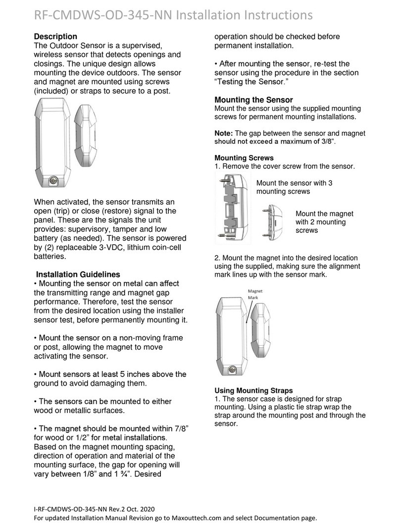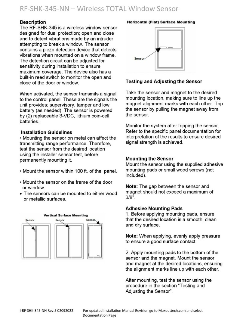
RF-SHK-319-NN Wireless TOTAL Window Sensor
I-RF-SHK-319 Rev.3 Oct. 2020 For updated Installation Manual Revision go to MaxoutTech.com and select Documentation page
2.
Apply double-sided tape to the bottom of
the sensor and the magnet. Mount the
sensor and magnet at the desired locations,
ensuring the alignment marks line up with
each other.
Programming
The following steps describe the general
guidelines for programming the sensor into
panel memory. Refer to the specific panel’s
documentation for complete programming
details.
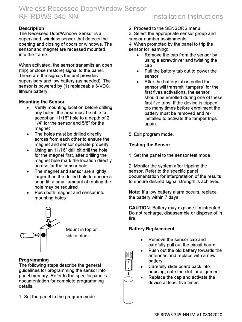
The internal magnetic reed switch and
shock zones use separate ID’s
Concord Control Panel – both ID’s are enrolled
at the same time
•Enter system programming
•Sensors
•Learn Sensor
•Trip Sensor
•Activate sensor tamper – the panel will
enroll (2) zones
•First zone enrolled is shock
•Second zone enrolled is reed switch
Simon/Zerowire – each ID is enrolled separately
•Enter system programming
•Sensors
•Trip Sensor
•Activate sensor tamper to enroll shock
•For next zone number, remove sensor
batteries, while holding the tamper re-
insert batteries, this will enroll the reed
switch
Qolsys - each ID is enrolled separately
•Enter system programming
•Sensors
•Trip Sensor
•Activate sensor tamper to enroll shock
•For next zone number, remove sensor
batteries, while holding the tamper re-
insert batteries, this will enroll the reed
switch
Note: Panel model numbers variations may
cause a ‘sensor already learned-in’ message
inhibiting the shock sensor for learning in. If this
is the case, learn in the reed switch using a
magnet to trip the reed, and learn-in the shock
zone by tapping on device to activate it.
Exit program mode.
Testing and adjusting the Sensor
1.
Set the panel to the sensor test mode.
2.
Take the sensor and magnet to the
desired mounting location, making sure to
line up their alignment marks with each
other. Trip the sensor by pulling the magnet
away from the sensor.
3.
Monitor the system after tripping the
sensor. Refer to the specific panel
documentation for interpretation of the
results to ensure desired signal strength is
achieved.
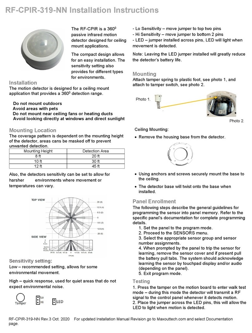
Shock LED Functionality
LED is functional only in test mode. Test
mode is entered automatically when
batteries are inserted. LED activates on
shock activation and goes out upon shock
restoral.
Test mode stays on as long as the cover is
removed.
Batteries must be removed and re-installed
to initiate test mode after expiration.
Low battery detect. LED flashes until battery
is replaced. Device sends low battery
signal to control panel.
Shock sensor sensitivity setting
An LED test mode (see above) is included
to aide in setting sensitivity to desired level
1.
Mount sensor in intended location
and tap mounting surface with
desired level of activation impact
2.
Adjust potentiometer until correct
sensitivity is obtained
The potentiometer adjusts shock sensitivity
from minimum Low (CCW) to maximum Hi
