MaxPower CT25 Owner's manual

Last update: February 2018
Manual CT25
www.max-power.com
CT25
With electronic thruster control
INSTALLATION OPERATION
MAINTENANCE
Serial No.: ------------------------------------------------------
Installation date: -------------------------------------------------
THIS MANUAL MUST BE KEPT ONBOARD AT ALL
TIMES
Via Philips 5, 20900 Monza (MI), Italy
Tel. +39 039 200 1973-936 - Fax +39 039 2004299
www.max-power.com E-mail:contact@max-power.com

Last update: February 2018
Manual CT25
Section
Title
Page
1
General installation guidelines
2
2
Tunnel
3
3
Composite motor support and drive leg
4
4
Electric Motor
5
5
Propellers
5
6
Protection grills
5
7
Electrical installation
5
8
Main power fuse
6
9
Batteries
6
10
Electronic control box
7
11
Control panel and thruster control box functions
7
12
Control panel installation
8
13
Tests
9
14
Electrical measurements
9
15
Operation
9
16
Alarms or thermal switch-off
10
17
Safety
10
18
Maintenance
10
19
Electrical installation diagram
11
20
Relay and control box connections diagram
12
21
Spare parts diagram
13
22
Spare parts list
14
23
Troubleshootingguide
15
24
Worldwide distribution network
15
25
Warranty coverage
16
26
Warranty form
18
The use of qualified marine personnel, with experience in bow thruster installation, is
strongly advised. Where possible, the boat manufacturer’s design departments, architects,
and/or shipyards should be consulted, prior to installation taking place. For any boat requiring
official classification, bodies of approval should also be consulted at the earliest opportunity.
In any case, all other bodies, governmental or otherwise, should be contacted to ensure
conformity with legal regulations relating to the boat in question.
IT IS ESSENTIAL TO READ THE FOLLOWING MANUAL
CAREFULLY
BEFORE INSTALLING THE
THRUSTER
NB : The thruster is delivered without accessories (fuse, fuse holder, control
panel).

Last update: February 2018
Manual CT25
•
The minimum acceptable tunnel position is 82 mm below the waterline
•
The tunnel is ideally positioned when the distance between the waterline
and the top of the installed tunnel is 110 mm
•
The tunnel must be installed as far forward as possible
NB: A thruster turbine installed above its ideal position towards its minimum depth will
lead to a progressive loss of performance.
Whether vertical, inclined or horizontal, it is recommendedto support the electric motor.
The electric motor generates heat when in operation. The zone in which the thruster is
installed must therefore be dry and ventilated.
The batteries used by the thruster must be charged by both the main engine's alternator
and an appropriate battery charger.
If the thruster is installed using a dedicated battery bank, this must be as close as
possible to the thruster in order to reduce voltage loss in the electric cables.
CAUTION: In no case should flammable products be stored near to the electric
components of the motor.
The propeller must be centered in the tunnel.
In no case should the propeller protrude out of the tunnel.

Manual CT25
Last update: February 2018
www.max-power.com
3
2. TUNNEL
Once the final tunnel position has been determined and all dimensions have been
checked, mark the center-point of the tunnel on both sides of the hull and drill holes of
8 –10 mm ∅on either side.
Using a metal rod, construct a compass with a 55mm radius. Insert through the holes and
trace the ellipses, as shown below.
After cutting the holes out following the elliptical guidelines, use an abrasive disc to
prepare the inside and outside surfaces of the hull for laminating (approx. 10 to 15cm
around the holes).
Position the tunnel in the hull, mark the positions of the different components, as well as
the areas that require laminating, and then remove the tunnel. It is advisable to drill the
tunnel before laminating it into position. See section 3 "Composite Motor Support and
Drive leg" for more details.
Replace the tunnel. To secure its position apply reinforced fiberglass filler to all areas,
both inside and outside, in order to entirely fill the space between the hull and the tunnel.
Laminate using a minimum of 8 layers of ISOPHTALIC RESIN alternated with mat and
roving.
In areas of difficult accessibility (i.e. under the tunnel), it is possible to only apply
reinforced filler.
Once the filler has been set on the outside, finish with a waterproof under coat, followed
by sanding and application of a waterproof finish coat.
In order to optimize the flow of water whilst sailing and to avoid turbulence due to the
tunnel, leave 1 to 4 cm of finish these with several coats of reinforced filler in order to
obtain the required hydrodynamic lines.
Once all laminating work is complete, apply a watertight barrier.

Manual CT25
Last update: February 2018
www.max-power.com
4
DO NOT LAMINATE THE AREA OF THE TUNNEL TO WHICH THE ELECTRICAL MOTOR
SUPPORT WILL BE FIXED.
3. COMPOSITE MOTOR SUPPORT AND DRIVE LEG
The propeller must be at the center of the tunnel. The motor support and the drive leg will
therefore not be centered in the tunnel.
Locate and mark the intended position of the holes for the fixing screws and the leg hub.
You can use motor’s support and leg’s gasket to mark these holes.
In some cases it will be easier to mark and drill these holes BEFORE laminating the
tunnel.
After drilling, use the gasket to verify the holes’ axes and adjust them with a round file
where necessary.
These holes must be completely clean before inserting the screws.
Position the leg, the gasket (between the leg and the tunnel) and the motor support,
and then tighten the two screws alternatively. Finally, mount the propeller to control the
general alignment.
If the general set-up is correct, remove the propeller, the leg and the gasket.

www.max-power.com
5
Last update: February 2018
Manual CT25
Apply a thin coating of silicon grease or sealing compound to both sides of the gasket
(this must be hydrocarbon and water resistant). Re-assemble all parts as before,
position and then tighten the two 6mm screws alternatively using a 5mm Allen key
(maximum torque: 12 Nm).
Check that the propeller rotate freely without resistance or friction.
It is imperative that the holes and the screws remain free of sealing compound,
otherwise there is a risk of an incorrect assembly of the parts.
Caution: do not use graphite grease.
NOTE:
The composite drive leg:
•
is pre-filled with oil and sealed for its lifetime circle
•
does not require anodes
•
must not be disassembled, even partially (terminates warranty)
4. ELECTRIC MOTOR (12 volts)
After having greased the motor’s shaft and the drive pin, place the motor on its
support. The motor should center itself and align easily when correctly mounted on its
support.
If not, drive leg, motor support and tunnel are incorrectly assembled. Most likely due to
an uneven surface on the outside radius of the GRP tunnel.
For the latter case, disassemble the motor support / drive leg assembly, sand the tunnel
so as to achieve a smooth exterior radius and repeat the previous steps.
Position the four 6 mm motor support screws, then tighten them alternatively
(maximum torque: 20 Nm).
5. PROPELLER
Insert the drive pin and propeller.
Check that the propeller turns without resistance (small resistance due to the motor is
normal).
Gradually tighten the 13 mm nut, while holding the propeller tightly with your hand
(maximum torque: 10 Nm).
Protect your hands during this operation to avoid risk of injuries caused by the edges of
propeller.
IMPORTANT: to avoid calcium deposits that could damage the seals, we
recommend that you coat the shaft and stainless steel cover with silicon grease.
6. PROTECTION GRILLS
It is possible to install protection grills; however installation of such grills will affect
thruster performance.
7. ELECTRICAL INSTALLATION
CAUTION: an incorrect electrical installation will cause rapid deterioration or even failure
of the thruster. Excessive voltage drop will cause premature wearing of the relays and
brushes. Special attention should be given to the quality, capacity and condition of your
batteries, as well as wiring sections that are used.

www.max-power.com
6
Last update: February 2018
Manual CT25
Ensure that all electrical connections are correctly tightened.
Under no circumstances any flammable products not to be stored next to
electrical components of the thruster.
It is essential to install a manual battery isolator and if possible an electric
battery isolator at the base of the thruster motor power line.
When using a manual battery isolator it must be visible, clearly marked & easily
accessible.
Thruster motor power supply:
These values are given as an indication, assuming that the batteries are charged at
100% and in charge and charging voltage should be 13.8V.
The performance data of the CT25 is measured with an approx. consumption of
250 Amps and approx. 11V at the motor’s connections.
Please refer to the characteristics given by the manufacturer of the batteries that will be
used (see section 9 “Batteries”).
Power wiring:
Measure the shortest and most direct route possible between the battery(ies) and the
electric motor; remembering to allow for both “positive and negative” wires.
Recommended cable sections:
Cable lengths
CT25 12 V
L ≤5 m (2,5 x 2)
50
mm²
5< L ≤10 m (5 x 2)
70
mm²
10 < L ≤15 m (7,5 x 2)
95
mm²
15< L ≤20 m (10 x 2)
120
mm²
For all connections, use appropriate terminals for the cable sections chosen.
It is possible to reduce the cable section to facilitate easy connection but only over a
short distance. In this case, appropriated crimp fittings should be used at the
connections.
Please consult the "Electrical installation" diagram p. 11 for more information
8. MAIN POWER FUSE
Fuse sizes for overcurrent protection are to be determined on the basis of the cable
sections in the circuit and NOT the amperage drawn by the appliance (thruster motor) in
the circuit.
Thruster
Maximum Amperage
Max Power Fuse size
CT25
250
A
125
A
9. BATTERIES
Thrusters are high amperage consumers with instantaneous demands, thus, we
recommend you use maintenance-free“starting” type batteries, with high CCA
outputs.
For
example: Exide Maxxima 900, 12V, capacity 55Ah / starting current 800CCA.

www.max-power.com
7
Last update: February 2018
Manual CT25
10. ELECTRONIC CONTROL BOX
Install a fused circuit breaker / switch in the boat's main DC distribution panel marked
BOW THRUSTER.
This circuit breaker / switch should ideally be supplied from a different battery bank to the
one used for powering the thruster.
The installer must protect the positive supply cable of the thruster’s control box by means
of a 8A fuse. The size of the power cables (red & black) depends on the length of the
cable run, the voltage drop in these cables should not exceed 5% of the nominal battery
voltage.
For safety reasons, and in order to obtain all the functions provided by the thruster
controller, an electric battery isolator needs to be installed in the thruster’s motor positive
supply cable.
Max Power advises the use of an electric battery isolator ref. 318400.
If an electric battery isolator is not used then simply seal-off the two grey wires coming
out of the control box. It is important to isolate the thruster motor power circuit by means
of a manual battery isolator after having used the thruster.
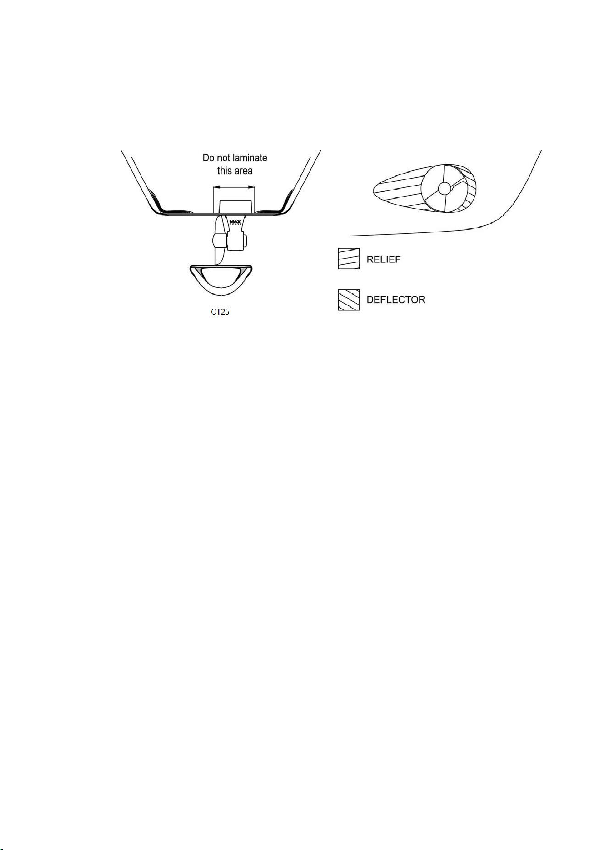
Please refer to the drawing “Relay and control box connections” p. 12 for more
detail on the wiring of the control box to the thruster.
11. CONTROL PANEL AND THRUSTER CONTROL BOX FUNCTIONS
To switch the thruster ON or OFF follow the instructions given in the diagrams on the
following page.
When switched ON the control panel will beep once and the green LED in the red push-
button will light up.
When switched OFF the control panel will beep twice and the green LED in the red push-
button will go out.
The thruster controller provides a time delay between left and right thrust in order to avoid
rapid direction changes. There is no delay when thrusting to same side.
If the thruster motor overheats, the control panel will start beeping and the green LED will
flash until the thruster motor has cooled down.
As soon as the overheating alarm sounds, only 10 seconds of usage of the thruster
remain before the unit automatically shuts down. Then, it will not be possible to switch the
thruster on until the motor has cooled down.
If the thruster has not been used for a period of thirty minutes it will automatically
switch itself off.
Before switching off automatically, the control panel will beep once followed by a second
beep a few seconds later, after which the thruster switches itself off.
In order to isolate the thruster motor power circuit, as described in the previous two
paragraphs, it is necessary to install an electric battery isolator, as advised by Max
Power.
Please consult the "Electrical installation" diagram p. 11 for more information

Manual CT25
Last update: February 2018
12. CONTROL PANEL INSTALLATION
Control panels should be protected from the natural elements while the thruster is not in
use.
Install the control panel(s) in easily accessible positions, without obstructing the main
engine and/or steering controls.
When fixing the panel with the stainless steel screws, make sure to install the pre-cut
rubber seal, as supplied with the panel, ensuring that it is in the correct place.
Only when totally finished and satisfied with the wiring and positioning of the unit,
clip-on the face panel/cover.
Please note that panels are only fully waterproof from their front side, if installed correctly.
However the area behind the dashboard should be kept dry to avoid the risk of
oxidization of the cable connector contacts.
For full control panel installation instructions, please refer to the "Installation
Guidelines" as supplied with each control panel.
www.max-power.com 8

Manual CT25
Last update: February 2018
www.max-power.com
9
13. TESTS
Activating the thruster when the boat is out of the water, is not advised under
any circumstances.
Tests must be carried out with the boat in the water, battery(ies) charged at
100% and in charge, and the engines running.
The maximum continuous operating runtime corresponds to S2-3mn norm.
However, this can be affected by the ambient temperature.
14. ELECTRICAL MEASUREMENTS
In normal “usage” mode, i.e. thrusters running, boat in the water, with fully charged
batteries under ongoing charge (alternator), electrical measurements should be made at
the following points:
At the batteries
At the battery cut-off switch
At the fuse
At the electric motor’s connections
At the power supply arriving at the thruster control box
These measurements will enable you to detect voltage drop.
NOTE: the voltage reading between the motor’s negative and positive connections
should be approximately10.5V during operation.
The cumulative effect of voltage drops at these points can severely impair the
thruster's performance.
If the voltage measurement is too low, the following assumptions need to be
checked:
Are the batteries of sufficient capacity ?
Are the batteries in good quality?
Are the batteries sufficiently charged?
Are appropriate cable sections being used?
Are the connections sufficiently tightened?
15. OPERATION
With the control system circuit breaker/ switch and manual battery isolator switched on:
Switch on the control panel, as previously described in the manual.
Push the red button or incline the joystick to the left and the boat moves to the left.
Push the green button or incline joystick to the right and the boat moves to the right.
If, during tests the boat moves in the wrong direction, change around the blue and the
brown wires on your power relay.
When maneuvering remember that the boat’s momentum continues after you release the
joystick / button, therefore remember to release the control prior to reaching your desired
position.
Attention must be paid for not use the thruster in areas where people may be
swimming or floating debris.
Maximum running time: 2-3 min (depending on ambient temperature).

Manual CT25
Last update: February 2018
10
www
.max-power.com
16. ALARMS OR THERMAL SWITCH-OFF
The thruster's electric motor is fitted with a thermal switch as standard. If the thruster
motor overheats the buzzer in the control panel will start beeping and the green LED in the
red-push button will flash until the thruster motor has cooled down again.
As soon as the overheating alarm sounds, there are 10 seconds of actual thruster use
before the unit automatically shuts down. The unit will then not be able to be switched on
again until the motor has cooled down.
17. SAFETY
Switch off means to cut the power at both the DC equipment panel (control power supply)
& the thruster battery isolator (thruster power supply) after having used the thruster.
Under no circumstances should any flammable products be stored next to the electric
components of the thruster. Care must be taken not to use the thruster in areas where
there may be people swimming or in the water close to the thruster.
CAUTION: Never involve in maintenance procedures with the thruster / thruster turbine if not
100% sure that both the control and power circuits have been isolated, except if taking
electrical measurements on the thruster motor or relay.
18. MAINTENANCE
Control panels should be protected from the natural elements while the thruster is not in
use.
The thruster requires a minimum of ongoing maintenance:
Check the condition and charge of the batteries regularly, as voltage drop is the most
frequent cause of rapid deterioration of the relay.
Carry out a regular check of all electric components: batteries, connections, power
cables.
Remove the motor and clean out dust from the motor-brushes with compressed air.
The electric motor must be kept dry and well-ventilated.
NOTE: All maintenance should be carried out by qualified and authorized personnel.
Composite drive leg and propellers:
The composite drive leg is pre-filled with oil and sealed for its lifetime circle. It does not
require the oil changing.
The composite drive leg does not require an anode.
The composite drive leg must not be disassembled, even partially (this would void the
warranty).
When the boat is out of the water, check that there are no fishing lines, plastic bags, etc.
caught in the propeller.
Paint the drive leg and propellers with antifouling (make sure that they were well
prepared and primer has been used). Always keep the propellers and tunnel clean.
To prevent the build up of calcium on drive shafts, which would damage the oil seals, cover
the drive shaft and the oil seals’ stainless steel covers with silicon grease before fitting the
propeller. This should be done on an annual basis after the cleaning of the outside of the
leg. Do not use aggressive solvents as they may damage drive leg seals.
If drive leg oil seals are found to be worn, replace the drive leg with a standard exchange
unit.
THE MAX-POWER TEAM WISHES YOU SUCCESSFUL MANOEUVRING
AND
ENJOYABLE
CRUISING

Manual CT25
Last update: February 2018
14
www
.max-power.com
22. SPARE PARTS LIST
N°
Description
Quantity
Part Number
1
Electric Motor CT 25
1
636059
2
Screws
4
-
3
Key
1
633578
4
Coupling
1
636082
5
Flange Screws
4
-
6
Motor Flange
2
Contact MAX POWER
7
Motor Support
1
636083
8
Screws
2
633557
9
Leg Gasket
1
310255
10
Driveleg CT25 (comprises n° 8, 9, 11, 13)
1
636098
11
Propeller Pin
1
636080
12
Propeller Φ110
1
35030
13
Inox Nut Φ8
1
634969
14
Fuse Holder T1
1
35017
15
Fuse 125A
1
35021
16
Electronic Controller
1
315310
17
Relay 12V
1
312921
18
Plastic Nut M4
2
312038
19
Cover
1
313734
Heat Sensor
1
311363
Extraction Handle for T1& T2
1
312882

15
www
.max-power.com
Manual CT25
Last update: February 2018
23. TROUBLESHOOTINGGUIDE
Before contacting your nearest Max Power distributor, please check the below
troubleshootingguide.
Problem
Check
The control panel does not light
up
•
Check the 6 wire connector behind the joystick
•
Check the thruster's electronic control box 6 wire
connector
•
Check the circuit breaker / switch in the boat's
main DC distribution panel
•
Check the control box's power fuse (8 A)
The relay is clicking but the motor
is not running
•
Check the motor's power fuse
•
Check the main battery isolator
•
Check the internal relay contacts
•
Check battery conditions and connections
The motor is running but the
thruster is not working
•
Check the propeller is fitted
•
Check the motor / drive leg assembly
•
Check that the tunnel is not obstructed or the
propeller blocked
The thruster lacks power
•
Check the propeller is fitted
•
Check the size of the batteries
•
Check the batteries are sufficiently charged
•
Check the connections are tightened correctly
•
Check the power cables sections
(See p. 6 : Recommended cable sections)
24. WORLDWIDE DISTRIBUTION NETWORK
To locate the nearest Max Power distributor, please consult the section
"Worldwide Distribution" on our website: www.max-power.com

Max Power
5, Via Philips Str, 20900, Monza (MI), Italy
Tel: +39 (0) 39 2001973 - 936, Fax: +39 (0) 39 2004299
Introduction
The
purpose
of this
document
is to set out the
terms
of
warranty
cover
offered
in
relation
to
products purchased
by the End User
from Max
Power or its
approved network
of
resellers.
1. Definitions
Authorized Repair Number:
The
number given
by Max Power on
reporting
a
fault with
your
thruster
Dealer:
An
authorized
Max Power sales
centre
End
User:
The boat
supplied with supplied equipment
and the
ownerthereof
Installer:
The
authorized centre responsible
for the
installation
of your
thruster
Manufacturer:
supplier
of the
equipment under warranty
Pleasure Craft:
Vessels used for
owner’s personal
use
that
have no
commercial
use (i.e
Charter
boats or work
boats)
Resellers:
Max Power
approved distributors
and
dealers
Serial Number:
Number
in
upperright
hand
corner
of
Warranty document
Supplier:
The
manufacturer
(Max
Power)
Warranty:
The
terms
and
conditions that
are
covered
by the
manufacturer
2. Period
of
Coverage
The
equipment manufactured
by the
Supplier
is
guaranteed
to be free
from defective workmanship, components
and
materials under normal
usage
conditions
for a
period
of
three
(3) years
from
the date of
purchase
by the End User. This
warranty
is
transferable
to
subsequent owners
of this
equipment during
the
period
of
coverage.
3. Warranty Registration
Register
your
purchase
now at
www.max-power.com.
(NB.
proof
of
purchase must
be kept
throughout
the
warranty period)
4. Warranty Terms
If the
material
is used for
anything other
than for
pleasure craft,
the
guarantee
is
limited
to a
six-month period.
Year
1: All
factory testing, diagnosis,repairs
and
replacements
are
performed
at no
charge
to the End User; All parts and up to two hours
of
labour
are
covered
for
repairs
and
replacements conducted
in the
field.
Year
2 & 3: All
factory testing, diagnosis,repairs
and
replacements
are
performed
at no
charge
to the End
User.
This
excludes
any
damage
or
faults occurring from normal
wear and tear on the
following items: engine,
oil seals, relay
contacts(If warranty is
registered within
the 3
month period following installation)
5. Warranty Exclusions
Damage
due to
modifications
or
installation contrary
to
published specifications
Cost of
hauling
the
boat
Damage
due to
repairs performed
by an
unauthorized service centre
Damage
due to lack of
normal maintenance services
Damage
due to
water
Parts
replaced
due to
normal
wear and
tear
Repairs
performed without knowledge
of
manufacturer (please contact dealer
to
receive
Repair
Authorization Number)
Tampering
of
equipment
by the End
User
Cost of
travel
to and
from
the job
site
Cost of
economic
loss,
including injury
to any
person, damage
to
property,
loss of
income
or
profit, communication, lodging,
inconvenience
Consequential damage
due to
failure, including
those
arising from collision with other
vessels or
objects
6. ProceduralGuidelines
PLEASE
VIEW THE TROUBLE SHOOTING LIST ON THE MANUAL OF YOUR PRODUCT TO ASCERTAIN OR SOLVE ORIGIN OF PROBLEMPRIOR TO
CONTACTING THE DEALER/INSTALLER
1.
Contact
your
dealer/installer
to
report
the
problem.
If you do not know who this is,
contact
the
nearest
Max Power
distributor
If you are in
foreign waters,
please
contact
the
nearest
Max Power
distributor
2. Ensure you have your serial
number
and
model number
to hand (top
right
hand
corner
of
warranty)
3.
Dealer/Installer
will come to site to
decipher
the cause of the
fault
4. If the cause of
fault
is due to a
manufacturing problem
the
dealer
will
contact
Max Power to
receive
Repair
Authorization Number.
5. If the
problem
is due to an
installation error
please
contact
your
installer.
IF POSSIBLE:
PLEASE
TAKE
PHOTOGRAPHS
OF THE THRUSTER TO SHOW PROBLEM
7. ServiceCenters
Please go
online www.max-power.com
to find the
authorized service station
of your
area.
The
warranty
as
outlined above
is
only applicable
to Max Power
manufactured thrusters
and
optional equipment
as used in
marine pleasure industry.
The
supplier holds
the
exclusiveright
to
test
the
product and
determine whether it
is
defective
1 / 2
Table of contents
Popular Controllers manuals by other brands

Linear Technology
Linear Technology DC1588A Demo Manual

Curtis
Curtis 1232E manual

Adaptec
Adaptec 2120S - SCSI RAID Controller Installation and user guide

Martin Audio
Martin Audio AQX - SCHEMATICS manual

Surefire
Surefire BMS-300 Installation & operation manual

Rockwell Automation
Rockwell Automation Allen-Bradley MicroLogix 1400 Series user manual