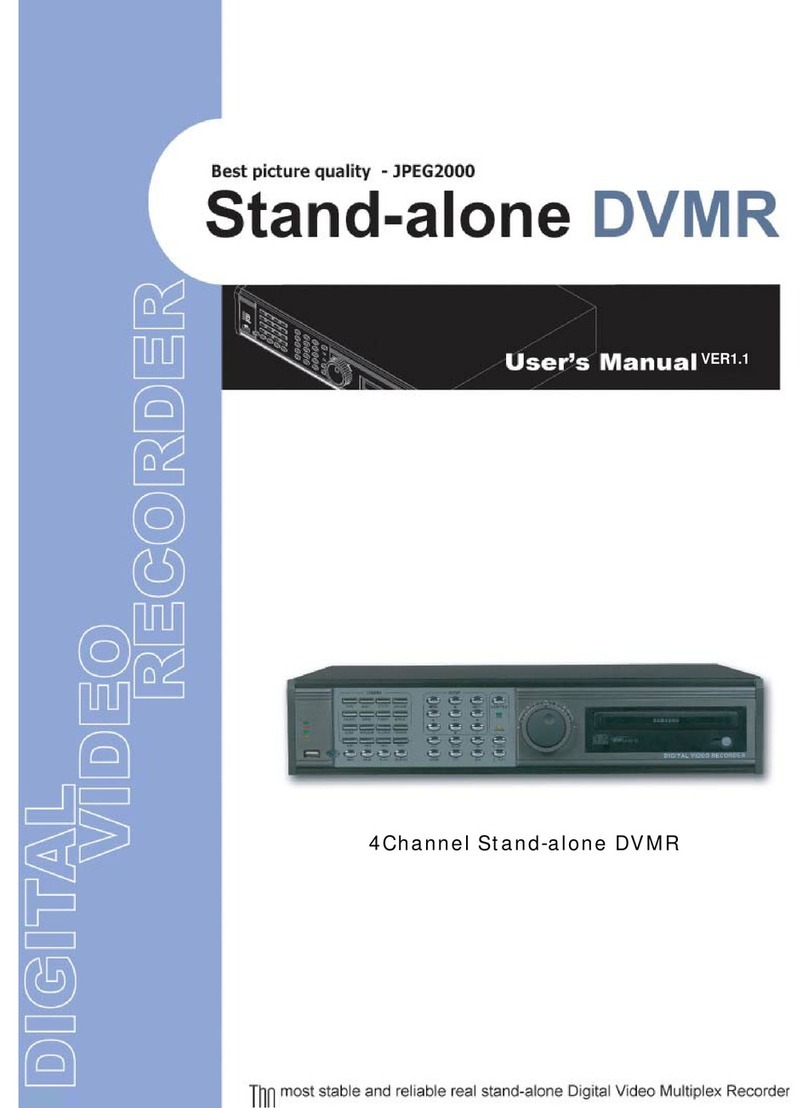
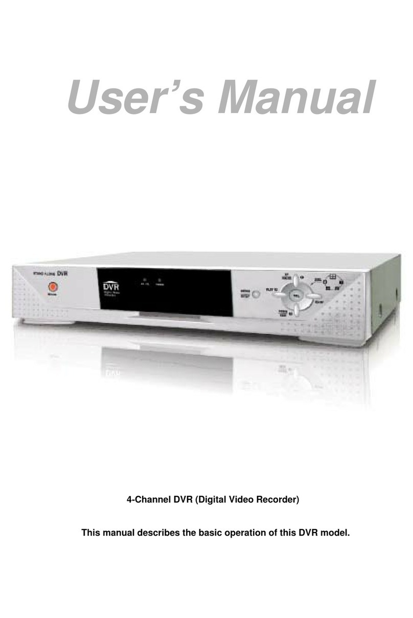
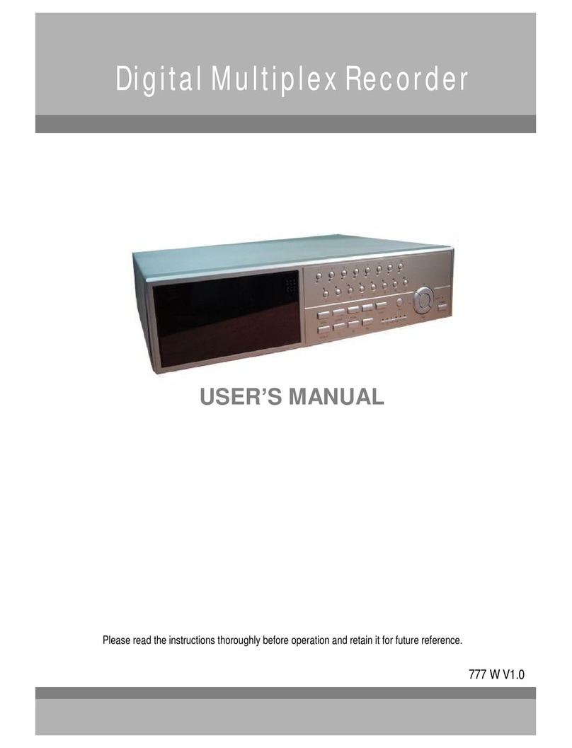
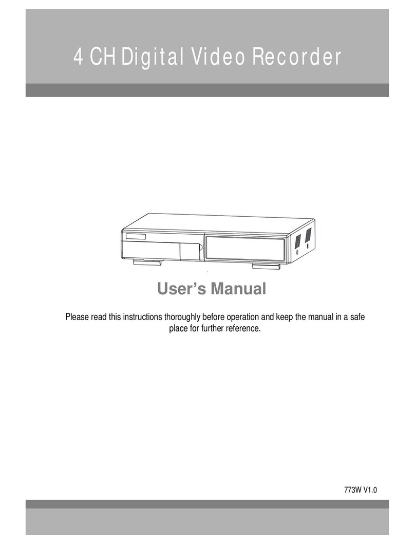
Maxtor 4 CH Digital Multiplex Recorder User manual

4CHDigitalMultiplexRecorder
User Manual
773 V 0.9
Please read this instructions thoroughly before operation and keep the manual in a safe
place for further reference.

Thelightningflash with arrowhead symbol, within an equilateraltriangle, is intended toalert
the userto the presence of uninsulated "dangerous voltage" within the product's enclosure that
maybe of sufficient magnitudeto constitute ariskof electric shockto persons.
The exclamation point within an equilateraltriangle is intended to alert theuser to the presence
of important operatingand maintenance-(servicing)instructionsin theliterature accompanying
the appliance.
All the safety and operating instructionsshould be read before operation. The improper operation maycause
permanent damage.
Please usetheprovidedadaptor (Other adaptor is not suitable for this machine).
Please lift andplace this equipment gently.
Donot exposethis equipment to open sunlight.
Donot use this equipmentnear water or in contact with water.
Donot spill liquid ofany kind on the equipment.
Please power downtheunit before unplugging.
Donot switch the Power On& Off within short periodof time (within 3 seconds).
Donot attempt to service this equipmentby yourself.
Installation should bemadeby qualified service personnel.
WARNING
1
DMR

2
What do youget
What do youget ?
?
FEATURES ---------------------------------------------------------------- ------------------------
PACKAGE CONTENT ---------------------------------------------------------------- ----------
Before Operation
Before Operation
INSTALLATION GUIDE ---------------------------------------------------------------- --------
FRONTPANEL ---------------------------------------------------------------- -------------------
BACK PANEL ---------------------------------------------------------------- ---------------------
Basic Operation
Basic Operation
STARTTHIS UNIT ---------------------------------------------------------------- ----------------
OPERATION---------------------------------------------------------------- ------------------------
Detailed Menu Setup
Detailed Menu Setup
ACCESS MENU ---------------------------------------------------------------- ------------------
MAIN MENU---------------------------------------------------------------- -----------------------
MENU OPTIONS ---------------------------------------------------------------- -----------------
MOTION DETECTION ---------------------------------------------------------------- ----------
Advanced Operation
Advanced Operation
OPERATION OPTIONS ---------------------------------------------------------------- --------
KEY LOCK ---------------------------------------------------------------- ------------------------
RS-232 PROTOCOL ---------------------------------------------------------------- ------------
Trouble Shooting ---------------------------------------------------------------- ------------------
Specifications ---------------------------------------------------------------- ----------------------
APPENDIX #1 INSTALLING THE HDD ----------------------------------------------------
APPENDIX #2 PIN CONFIGURATIONS ---------------------------------------------------
APPENDIX #3 RACK MOUNT ----------------------------------------------------------------
APPENDIX #4 RECORDING SPEED -------------------------------------------------------
DMR
TABLE OF CONTENTS
3
3
4
5
7
8
8
10
10
11
14
16
17
17
17
18
19
21
23
24

FEATURES
DVR Features
lWavelet compression format replaces Time-Lapse VCR + Multiplexer / Quad
l4 audio inputs / 2 audio outputs
lOn Screen Displayand Remote Control via Video Server & PC
lPicture-in-picture (PIP) in live
lMotion detection & motion trigger recording function
lAlarminput & output function
lVideo loss detected on each channel
lLinear Zoom(2x~4x)
lMultiplexer & Quad recording mode switching
lRecording rate up to full size 30 images/sec. or Quad size 120 images/sec.
lSupport 1 removable HDD with hot-swap capability, IDETYPE (over 250 GB)
lQuickmultiple search bydate/time, alarm, full, motion list
lSecuritypassword protection
lRS-232, RS-485 communication protocol
3
What do you get ?
Digital Multiplex Recorder(with HDD cartridge) User Manual
2 Keys for Cartridge Power Adapter and Cord
NOTE : Pleasecheck the package to makesure that you receive the complete accessories which includes the
components shown above.
Accessories pack
PACKAGE CONTENT

1. Connect camerasand monitor to the DVR.
2. Shown below is an example of connecting theDVR to your existing Observation System.
3. Install HDD (The compatibleHDD Brands are listed in thefollowing table.)
Please refer topage.22 Appendix #1 for installation instructions.
*The HDD must be installed before turningon the DMR, but if HDD is not installed, the DVR wouldbefunctionedas 4 CH multiplexer.
4
INSTALLATION GUIDE Before Operation
Manufacturer Model Capacity Rotation
HITACHI Deskstar180 GXP(120 GB) 120GB 7200 rpm
HITACHI Deskstar7K250, HDS722516VLAT20 160GB 7200rpm
HITACHI Deskstar7K250, HDS722525VLAT80 250GB 7200rpm
IBM Deskstar120GXP(80GB) 80GB 7200 rpm
IBM Deskstar120GXP(120GB) 120GB 7200 rpm
Maxtor DiamondMax536DX(60GB) 4W060H4 60GB 5400rpm
Maxtor DiamondMaxPlus9 80GB 7200 rpm
Maxtor DiamondMaxPlus9, Model#6Y120L 120GB 7200 rpm
Maxtor DiamondMaxPlus9, Model#6Y160L0 160GB 7200rpm
Maxtor MaxLine Plus Ⅱ, Model#7Y250P0 250GB 7200rpm
Seagate Barracuda ATAIV, ST380021A 80GB 7200rpm
Seagate Barracuda ATAV, ST3120023A 120GB 7200 rpm
Seagate Barracuda 7200.7Plus, ST3160023A 160GB 7200 rpm
WesternDigital CaviarWD1200BB-00CAA1 120GB 7200rpm
WesternDigital CaviarWD2000BB-00DWA0 200GB 7200rpm
WesternDigital CaviarSE WD2500JB 250GB 7200rpm
COMPATIBLE HARD DISK MODELS

1. REMOVABLE HDD CARTRIDGE & KEYHOLE
Please refer to page.22 Appendix #1.
2. LED LIGHT
The LED Light is ON under following condition.
HDD : HDD status display
HDD Full : HDD is full
ALARM : To turn off theALARM LED light, please refer topage.14 and set the
ALARM modeas OFF.
TIMER : When Timer is set as Enabled
PLAY : On Playing mode
REC : OnRecording mode
3. MENU
Press MENU to enter main menu.
4. ENTER
Press ENTER for confirmation.
5. SEARCH
Press SEARCH for searchingrecordedvideo.
6. ZOOM
Press ZOOM toenlarge the picture display.
7. /+ Picture in Picture
Press PIP button for Picture inPicture screen, and + ”can be used for detail change.
8. /- 4 channels displaymode
Press ” button for 4channels display mode, and -”can beused for detail change.
9. SLOW
To slow down the speed of playing mode.
10. POWER
Press Power toturn ON / OFF the DMR.
5
FRONT PANEL DMR

11. REC
Press REC to start recording.
12. PLAY
Press PLAY to playback recorded video.
13. PAUSE / Up
Pause: Under DMR play mode, it can pausetheaction.
UP : Under setupmode, it works as Up button.
14. STOP / Down
STOP : Under DMR Record/ Play mode, it can stop the momentaction.
DOWN : Under setupmode, it works as Downbutton.
15. REW / Left
REW : Under DMR play mode, it can play video backward atdifferentspeeds. (Press REW again toadjust
speed as 1, 2, 4, 8,16,32 times)
Left : Under setup mode,it works as Left button.
16. FF / Right
FF :It canplay video forward at high speed, and press FF again toadjust speedfrom 1, 2, 4, 8, 16, 32 times.
Right :Under setup mode, it can work as Right button.
17. CAMERA SELECT (1-4)
Press the Camera Select (1-4) to select specified camera.
6

7
1. P0WER
Please use theprovided power cord (The adaptor is embedded).
2. EXTERNAL I/O
Controlled remotely by an external device or control system like Video WebServer.
Alarm input, external I / O explanation.
3. VIDEO INPUT (1-4)
Connect to video source,suchas camera.
4. MAIN
Connect to Main monitor.
5. CALL
Connect to CALL monitor. Show the Switch Display.
When alarm trigger happens,the call monitor will show the triggered channel for a period of time.
6. AUDIO IN (1-4)
Connect to audio sources, such as a microphone.
IPS should be set to 30 (for NTSC) or 25 (for PAL)
*4 audio inputs, but can onlyrecord one input at the same time.
7. AUDIO OUT (R/L)
Connect to monitor or speaker.
IPS should be set to 30 (for NTSC) or 25 (for PAL)
*with2 mono audiooutputs from the same source.
8. FAN
REAR PANEL DMR

Connect theAC Power Cord andplug intoan electrical outlet thenpress thepower switch ON”. TheRedLED
indicator light will be ON and the DMR is in Standby mode.
1.
Press the Power button. The POWER LED will turn from red to orange,and other redLED indicators will turn ON. It
takes approximately 5 to 15 seconds to boot the system with the message: HDD Detecting ”. Onceconnected, the
POWER LED will changetogreen color, and theAlarm LED will be ON.
2.
8
Before using theDMR, please have a HDDinstalled ready, or it willbefunctioned as 4 CH multiplexer (refer to Appendix #1
for installation or removal of aHDD).
GETTINGSTARTED Basic Operation
OPERATION
RECORDING
The DMR offers avariety of recording modes, suchas record continuously, by scheduled time, andby events. You can
set up recording speedand resolution.You can setthese options by selecting MENU /RECORD before recording, please
refer to page.13.Under therecording status, if power is off accidentally, recordedvideo will stillbe storedin theHDD.
DMR will returntooriginal recording situation after power restores again.
On the screen, you will find thedate, time, HDD recording type, theamount of available GB left in the HDD memory and
theletter ” represents the methodofrecording that is occurring.
(OW : HDD Overwrite)
NOTE : 1. When the HDD is full under O/W Recording mode,previousrecorded files
will be overwritten without further warning notices.
2. If the HDD capacity is only 5GB left, it willdisplay 5GB”on the up-right screen and shows orange
color, and it will buzz for seconds; soas in 4GB, 3GB, 2GB and 1GB.If the O/W Recording mode
(NOTE 1) is on, it won’t havethe warning buzzer.
There are4 recording modes:Alarm, Motion,Timer andManual Record.
1. ALARM RECORDING
DMR is triggeredby analarm input. symbol will be shownon the triggered channel.
2. MOTION TRIGGER RECORDING
Recording is triggered by motion detection. symbol will be shown onthe triggeredchannel.
3. TIMER RECORDING
Recording is scheduled by a Timer. Itwill indicate by the symbol .
4. MANUAL RECORDING
Recording is initiated manuallyby pressing the REC button. Symbol will be shown.
2002 JAN 01 01:02:03
OW
3. Before operating theDMR, setthe system time first. (refer to page.11).
NOTE : If the HDD is not installed correctly or not installed, the HDD not found”messagewill
appear only3 seconds and then return to 4CH Multiplexer displaymode.
PLAYBACK
Press PLAY ”button, theDMR will show the last recording.
1. FAST FORWARD (F.F.) & FAST REWIND (F.R.)
Youcanincreasethe speeds of Fast Forward and Rewind on the DMR.
In the Play mode,press ””oncetoget 2X speed forward and press twice to get 4X speed,…and the maximum
speed can reach 32X.
Press ”◄”once to get 1X speed rewindand press twice to get 2X speed, …and the maximum speed can reach
32X.
2. SLOW FORWARD (S.F.) & SLOW REWIND (S.R.)
Youcanalso slow down the speeds of Forward and Rewind on theDMR.
In the Play mode, press the SLOW button and you will enter Slow mode.
Press ”SLOW ”once toget 1/2X speed forward and press ””to get 1/4X speed,…andthe slowest speedcan
reach
1/32X.
Press ”◄”once to get 1/2X speed rewindand press twice to get 1/4X speed, …and theslowest speed can reach
1/32X.
3. PAUSE
It will let you pausethe current image displayed on thescreen.
4. STOP
Press STOP ”under any circumstance,DMR will return to live monitoringmode.
5. IMAGE JOG DIAL
It will allow you to manually view video frame-by-frame, oneimage at a time.
While in PLAY mode, press PAUSE ”, it will pause the screen.
Pressing ”buttonadvances the frozenscreenone image forward.
Pressing ◄”button moves back one image.
CAMERASELECT(1-4)
Press Camera Select (1-4) to select appointed camera todisplay on full screen mode.
9

There are12 options available in the MainMenu:
TIMER ---------- Programs Specific Time to Record
CAMERA ------- CameraChannelSetup
RECORD ------- Record Mode Setup
ALARM --------- Alarm Setup
DWELL --------- Dwell time Setup
PIP --------------- Picture in PictureSetup
MOTION -------- Motion Detection Setup
DISPLAY ------- Display Mode Setup
REMOTE ------- Remote Control Setup
USER ----------- User PasswordSetup
SYSTEM ------- System Setup
EVENT --------- Event List
10
Outlined below arethebuttons used for Menu setting :
Up”and Down”:Scroll up and downor change values when anoption is selected andis blinking
Left”and Right”:Scroll sideways within amenuoption thathas beenselected
+ ”and -”:Increase and decrease thenumber or change values whenan optionis selected and is blinking
ENTER : Selects a submenu / an option under a submenu for browsing / modification
MENU : Completes modification of amenu option; exits a menu
MAINMENU
Detailed Menu Setup
(MENU)
TIMER
CAMERA
RECORD
ALARM
DWELL
PIP
MOTION
DISPLAY
REMOTE
USER
SYSTEM
EVENT

MENU OPTIONS
SYSTEM
11
1. AUDIO INPUT
To choose oneof4 channels to record.(It can only record 1 input)
2. BUZZER
Set the BUZZER ON”, it will buzzer by eventoccurrence when the settingis ON.
6. HDD OVERWRITE
To setthe HDDOVERWRITE. When theHDD is full under O/W recording mode,previous recorded files
will be overwritten withoutfurther warningnotices when the HDDOVERWRITE is ON.
7. MESSAGE LATCH
To select whether theDMR messages will disappear after 10
second or remainon screen. NO is the default setting which the
messages will disappear after 10 sec.
NOTE : Video loss, Alarm and Motion messages will be shown
thesame as Alarm Duration time.
8. DATE DISPLAY
To set the date Y/M/D, M/D/Y, D/M/Y and OFF on monitor or not.
9. DATE
To set the date shown on the DMR.
10. TIME
To set the time on the DMR.
11. CLEAR HDD
Deleteall the contents of the HDD. When youchoose YES”on this option, press ENTER”and you
will be prompted withthequestion shown: Press ”to clear HDD or press ”←”to cancel.
12. SYSTEM RESET
Resetall system settings back to factory default settings.
DMR
3. EXT ALARM
To set the EXTERNAL AUDIBLE ALARM. It will be trigged by event occurrence
when thesetting is ON.
4. VLOSS ALARM
To set theVLOSS ALARM. When the settingis ON”, the alarm will occurrence by the setting
ofBuzzer, EXT alarm or Alarm Duration.
5. MOTION ALARM
To set the MOTION AUDIBLE ALARM. When the setting is ON”, thealarm will occurrence
by the setting of Buzzer, EXT alarm or Alarm Duration.
(MENU)
TIMER
CAMERA
RECORD
ALARM
DWELL
PIP
MOTION
DISPLAY
REMOTE
USER
SYSTEM
EVENT
(SYSTEM)
AUDIO INPUT1
BUZZER ON
EXTALARM ON
VLOSS ALARM ON
MOTION ALARM ON
HDD OVERWRITE YES
MESSAGE LATCH YES
DATE DISPLAYD/M/Y
DATE 26-DEC-2003 [FRI]
TIME 22:55:34
CLEAR HDD YES
SYSTEM RESETYES

TIMER
1. DAY
Select the day,or days of the week (Mon–Fri / Sat-Sun /Daily) thatyou wish to schedule
the DMR toautomatically record.
NOTE :
1. Special Date could be changed by “+”and “-”buttons.
2. If you have selected the specific date and recording timer set from that specific day
to a newday, then the Recording Timer Schedule will be set as whole week. For
specific date of Recording Timer Schedule, it is not recommended to setEnd Time
over 23:59. Forexample:If you set Timer Schedule Day as Sunday, and START
from 11:30, but End on 00:20, then Recording Timer Schedule is set as from every
Sunday's 11:30 to nextSunday‘s 00:20. If you only want to setRecording Timer
Schedule from every Sunday 11:30 to Monday 00:20, then you should set Recording
Timer Schedule as Sunday from 11:30 to 23:59, and Monday from 00:00 to 00:20.
2. START
Select the starting time for the recording.
3. END
Select the finishing time for therecording.
4. IPS
Stands for Images Per Secondand it could let you see Record submenu
for more details.
NTSC 30、15、8、4、2、1
PAL 25、12、6、3、2、1
5. QUALITY
Select the image quality for the recording. There are four Quality settings :
BEST, HIGH, NORM and BASE.
6. MODE
There are three record mode settings :
QUAD-FRAME, QUAD-FIELD, FULL-FIELD.
7. TIMER ENABLE
After sets up the recordingtimer, you can enable
or disable timer recording function., whenTIMER
ENABLE is ON”, press menu”button then you
can see thetimer setting diagram by your setting.
(TIMER)
DAY START END IPS QLT MODE
DAILY 01:00 22:00 30BEST Q-FR
OFF 00:00 00:0030 BEST Q-FI
OFF 00:00 00:0030 BEST Q-FR
OFF 00:00 00:0030 BEST Q-FI
TIMER ENABLE : ON
(MENU)
TIMER
CAMERA
RECORD
ALARM
DWELL
PIP
MOTION
DISPLAY
REMOTE
USER
SYSTEM
EVENT
12

13
3. RECORD (REC)
Set upwhich channel youwant torecord.
ON : when alarm input is triggered, DMR will record alarming channel more frequently.
For example : when CH01 is triggered, the record methodwill become 1-2-1-3-1-4….
OFF :DMR will not record.
4. BRIGHTNESS (BR)
Have a videobright adjustment ofeach channel. The level is from 0 to63.
5. CONTRAST (CT)
Have a videocontrast adjustmentofeach channel. The level is from 0 to 63.
6. COLOR (CL)
Have a videocolor contrastadjustment of each channel. The level is from 0 to 63.
7. HUE (HUE)
Have a videohue adjustment of each channel. The level is from 0 to63.
(RECORD)
RECORD IPS 30
QUALITYNORMAL
RECORD MODE QUAD-FRAME
(MENU)
TIMER
CAMERA
RECORD
ALARM
DWELL
PIP
MOTION
DISPLAY
REMOTE
USER
SYSTEM
EVENT
RECORD
1. RECORD IPS
Select the images per second of recording. The options are
as following :
NTSC 30、15、8、4、2、1
PAL 25、12、6、3、2、1
2. QUALITY
There are four quality settings : BASIC, BEST, HIGH, NORMAL.
NOTE : Therelationship of Record time, IPS and record quality,
pleaserefer to page.26 Recording Speed.
3. RECORD MODE
There are three record mode settings : QUAD-FRAME, QUAD-FIELD,
FULL-FIELD.
CAMERA
1. TITLE
Assign a title toeach camera. Initially each title is the camera’s number.
2. ALARM
Select LOW / OFF / HIGH for alarm polarity. Thedefault valueis LOW.
18151518ONHIGHCAMERA4
18151518OFFHIGHCAMERA3
18151518OFFOFFCAMERA2
18151518ONLOWCAMERA1
HUECLCTBRRECALARMTITLE
(MENU)
TIMER
CAMERA
RECORD
ALARM
DWELL
PIP
MOTION
DISPLAY
REMOTE
USER
SYSTEM
EVENT

ALARM
1. ALARM ENABLE
To set the ALARM ENABLE. It will be triggered by event occurrence whenthe
settingis ON.
2. ALARM DURATION
Set the reactiontime which was determinedby how long the alarm mode
respondedtoa buzzer. Default settingis 10 sec. Options are 10 SEC, 15 SEC, 20
SEC, 30 SEC, 1 MIN,2 MIN, 3MIN, 5MIN, 10 MIN, 15 MIN,30 MIN, ALWAYS, AUTO.
3. REC IPS
Select the images per second of recording duringan ALARM. The options are as following:
NTSC 30、15、8、4、2、1
PAL 25、12、6、3、2、1
4. QUALITY
There are four quality settings duringan ALARM : BASE, BEST, HIGH, NORM.
5. RECORD MODE
There are three record mode settings : QUAD-FRAME, QUAD-FIELD,
FULL-FIELD.
(MENU)
TIMER
CAMERA
RECORD
ALARM
DWELL
PIP
MOTION
DISPLAY
REMOTE
USER
SYSTEM
EVENT
(ALARM)
ALARM ENABLE YES
ALARM DURATION 15 MIN
RECORD IPS 30
QUALITYNORMAL
RECORD MODE QUAD-FRAME
DWELL
1. NORM
To set up theDWELL time period that each channel auto sequentially shows oncall
monitor. Thelevel is from 1 to 15SEC or OFF.
2. ALARM
To set up theDWELL time period whenalarm input is triggered.Thelevel is from 1 to
15SEC or OFF.
(MENU)
TIMER
CAMERA
RECORD
ALARM
DWELL
PIP
MOTION
DISPLAY
REMOTE
USER
SYSTEM
EVENT
(DWELL)
NORM ALARM
CAM1 01 01
CAM2 01 01
CAM3 01 01
CAM4 01 01
PIP
1. FULL SCREEN
To set up thefull screenbackground picture display.
2. PIP SCREEN
To set up thepicture with a 1/9size screen insert”.
3. POSITION
There are six position settings : D/L, D/M, D/R, U/L, U/M, U/R.
(MENU)
TIMER
CAMERA
RECORD
ALARM
DWELL
PIP
MOTION
DISPLAY
REMOTE
USER
SYSTEM
EVENT
(PIP)
FULL SCREEN CAM 1
PIP SCREEN CAM 2
POSITION D/R
14

15
MOTION
1. SEN (Sensitivity)
Sets thesensitivity of the Pixel-based Motion Detection featurefrom 1fo70.
2. MD-NVM
Sets thenumber oftargets in which Motion must occur in order to trigger an Alarm
(from 1-99 target areas).
Note: MD-NVM cannot be less than the number of targets set in the AREA.
3. RE
Sets theReference image to which the currentscreenis compared (from 1-99).
For example,the value 64 would compare the current image to the 64th previous
screen image.
4. DET
The motiondetection oneach channel setup can beturned to
ON or OFF individually.
(MENU)
TIMER
CAMERA
RECORD
ALARM
DWELL
PIP
MOTION
DISPLAY
REMOTE
USER
SYSTEM
EVENT
(MOTION)
SEN MD-NVMRE DET
CAM1 70 03 64 ON AREA
CAM2 70 03 64 OFF AREA
CAM3 70 03 64 ON AREA
CAM4 70 03 64 ON AREA
MOTION RECORD : ON
DAYSTART END
DAILY00 : 00 00 : 00
5. AREA
Press the ENTER buttonon this option to set the Pixel-based
Motion Detection Area for each channel. Green targets
represent the Motion Detection Area(Figure 1-2),and Purple
targets represent motion currently taking place (Figure 1-3).
To modify theMotionDetection Area, usethe following controls:
+: turns theselected target ON/OFF.
▲▼◄ : navigates between targets
- :turns all targets on the screen ON/OFF
Zoom: turns all targets in the selectedrowON/OFF
6. MOTION RECORD
When theDET settingis ON”, you can set upthe MOTION RECORD function,
1. Select ON”to set up themotion trigger record: It can automatically switch to RecordMode. The motion detection will
changethe scanningsequence andshows on themonitor.
NOTE: The trigger recording time will depend on ALARM DURATION mode setting (Please refer to page.11 for ALARM DURATION) and it will
record from the last trigger time. For example, when the alarm duration setting is 1 min, the recording time is from 9:00:00 to 9:01:00. If the
motion detection trigged again at 9:00:40, the trigged recording time will from 9:00:00 to 9:00:40and 9:00:40 to 9:01:40. The total
recording time is 00:01:40.
2. Select ”OFF”: The screen still shows and if it is in recordmode, the motiondetection will change the scanning
sequence.
For example :Ifthe motion is detected on Camera #1, its recording & scanning sequence will be more frequently. The sequence
will be as 1st, 2nd, 1st, 3rd, 1st,…4th. And channel 1 will show on the screen. If 2nd cameraand 3rd camera
both motion detection are activated, they will be scanning as 2st, 3rd, 1st, 2nd, 3rd, 4th, 2nd, 3rd,1st, 2nd, 3rd,
4th …and vice versa. And CH2 & CH3 will show for a period oftime which is same as Alarm Duration time.

16
Figure 1-1
MOTION DETECTION SETUP
1
2 3 4 5 6 7 8 9 10 11 12 13 14 15 16
1
2
3
4
5
6
7
8
9
11
12
Figure 1-2
MOTION DETECTION SETTING —ROW SETUP
Figure 1-3
MOTION DETECTION TRIGGERED-TURN INTO PURPLE
Figure 1-4
BACK TO MOTION DETECTION SETTING
1
2 3 4 5 6 7 8 9 10 11 12 13 14 15 16
1
2
3
4
5
6
7
8
9
11
12
1
2 3 4 5 6 7 8 9 10 11 12 13 14 15 16
1
2
3
4
5
6
7
8
9
11
12
1
2 3 4 5 6 7 8 9 10 11 12 13 14 15 16
1
2
3
4
5
6
7
8
9
11
12
7. DAY / START / END
To setup theDAY and the START/ END time for motiontrigger recording timer setting.
DISPLAY
1. TITLE DISPLAY
To set the title shown on monitor or not.
2. OSD COLOR
Select the OSD (On screendisplay) color. Theoptions are
YELLOW, WHITE, GREEN, BLACK, BLUE, RED, PINK, CYAN.
3. BORDER TYPE
To setthe BORDER TYPE on screen display.
Theoptions are 8/4,4/2, 2/1 or OFF.
4. BORDER COLOR
Select the BORDER COLOR. Theoptions are
YELLOW, WHITE, GREEN, BLACK, BLUE, RED, PINK, CYAN.
(MENU)
TIMER
CAMERA
RECORD
ALARM
DWELL
PIP
MOTION
DISPLAY
REMOTE
USER
SYSTEM
EVENT

REMOTE
1. REMOTE MODE
Set the remotemode for connection with computer via RS-232or RS-485.
(Please refer to page. 23for RS-232 Remote Control).
2. BAUD RATE
Set the remoteprotocol transmitting baud rate. Available options are 115200,
57600, 19200, 9600, 4800, 3600,2400, 1200.
3. ID
To control different DMR by setting
remote protocol. IDnumber can beset
from 000 to255.
(MENU)
TIMER
CAMERA
RECORD
ALARM
DWELL
PIP
MOTION
DISPLAY
REMOTE
USER
SYSTEM
EVENT
(REMOTE)
REMOTE MODE RS-485
BAUD RATE 9600
ID 255
USER
1. USER
To set up theuser account for controlling. It
allows 8 users setting.
Supervisor –Control all thefunctions.
Other User –Review all functions except the
menu settingand event list
cleaning.
2. PASSWORD
To set the security password for each account.
The maximum lengthof user password is 4
characters.
(MENU)
TIMER
CAMERA
RECORD
ALARM
DWELL
PIP
MOTION
DISPLAY
REMOTE
USER
SYSTEM
EVENT
(USER)
PASSWORD
SUPERVISOR 0000
USER 1 0000
USER 2 0000
USER 3 0000
USER 4 0000
USER 5 0000
USER 6 0000
USER 7 0000
18
(DISPLAY)
TITLE DISPLAYYES
OSD COLOR YELLOW
BORDER TYPE 4/2
BORDER COLOR WHITE
LOSS SCREEN GREEN
OSD POSITION NORMAL
5. LOSS SCREEN
Retain the last picture or selectthe LOSS SCREEN color.
Theoptions are GREEN, BLACK, BLUE.
6. OSD POSITION
To setthe OSD POSITION shown on monitor.
Theoptions are NORMAL or CENTER.

17
EVENT
C1 VLOSS 26-DEC-2002 03:00:00
C2 ALARM 26-DEC-2002 03:00:00
K UNLOCKS 26-DEC-2002 03:00:00
M-HD ERR 26-DEC-2002 03:00:00
M-HD WARM 26-DEC-2002 03:00:00
PWRREST26-DEC-2002 03:00:00
PMA ERROR 26-DEC-2002 03:00:00
M-HD REPL 26-DEC-2002 03:00:00
↑+↓: CLEAN
A single page can display 16 recorded events. Press ◄”or ”to changethe
pages or press ▲+ ▼to CLEAR the EVENT record.
DISK FULL: HDD is full
PWR REST : Power restored
M-HD REMS: HDD remove
M-HD REPL: HDD replace
M-HD ERR : HDD error
M-HD WARM: HDD warning
K UNLOCKS: Key is unlock
DMA ERROR: DMA error
C1 VLOSS : Camera 1 is video loss
C2 ALARM : Camera2 has been triggeredby external I/O alarm
C3 MOTION: Camera 3has been triggered by motion detection
SYSTEM ERROR: System might fail
CAM 2 VLOSS: Channel: 2 Video loss
CAM 3 ALARM: Channel: 3 External I/O Alarm havetriggered
POWER RESTORE : Power restored
(MENU)
TIMER
CAMERA
RECORD
ALARM
DWELL
PIP
MOTION
DISPLAY
REMOTE
USER
SYSTEM
EVENT

ZOOM
Press ZOOM button toenlarge the display ofmain picture. It displays zoomed picture on main picture anda
small window inserted. The inserted window contains a movable 1/4 view size of the appointed camera. The
range is from 2X to 4X.
•Press PIP : Zoom in
•Press QUAD : Zoom out
•Press the Zoom”buttonagain to leave thezoom pointer.
•Press Camera (1-4) toselect channel.
•Press ▲▼◄ to move the zoom position.
VIDEOLOSS
Screen will display ‘LOSS”in the center ofdisplay picture, if the video inputis not connectedproperly.
SEARCH
1. LAST RECORD
Play thelast recordedpiece of video.
2. FULL LIST
List all recorded video on theHDD which sorted by time.
3. ALARM LIST
List all recorded video triggeredby an Alarm.
NOTE : If there are no Alarm in the record,the screen will
display EMPTY”.
4. MOTION LIST
List all motion triggered records.
5. TIME SEARCH
Find video recordedon aspecific datethat is entered.
19
OPERATION OPTIONS Advanced Operation
: Motion Recording
: Manual Recording
: Alarm Recording
: Timer Recording
M : Storagein Master HDD
S : Storage inSlave HDD
NOTE: It will display different color oneach recordlist
mention above.
LASTRECORD
FULL LIST
ALARM LIST
MOTION LIST
TIME SEARCH
2003-JAN-01 01:02:03 M
2003-JAN-05 05:02:03 M
2003-MAR-12 04:02:03 M
2003-APR-02 03:02:04 M
2003-MAY-01 05:02:03 M
2003-AUG-09 01:02:01 M
: PAGE UP →: PAGE DOWN
Other manuals for 4 CH Digital Multiplex Recorder
1
Table of contents
Other Maxtor DVR manuals

Maxtor
Maxtor 4 Channel Stand-alone DVMR User manual

Maxtor
Maxtor DVMR User manual

Maxtor
Maxtor 4-Channel DVR (Digital Video Recorder) User manual

Maxtor
Maxtor Built in Digital Video Recorder User manual

Maxtor
Maxtor SSA-0412 User manual

Maxtor
Maxtor CDR-04S User manual

Maxtor
Maxtor 4 CH Digital Multiplex Recorder User manual

Maxtor
Maxtor pmn User manual

Maxtor
Maxtor Standalone DVR 2007 User manual

Maxtor
Maxtor 777 W V1.0 User manual