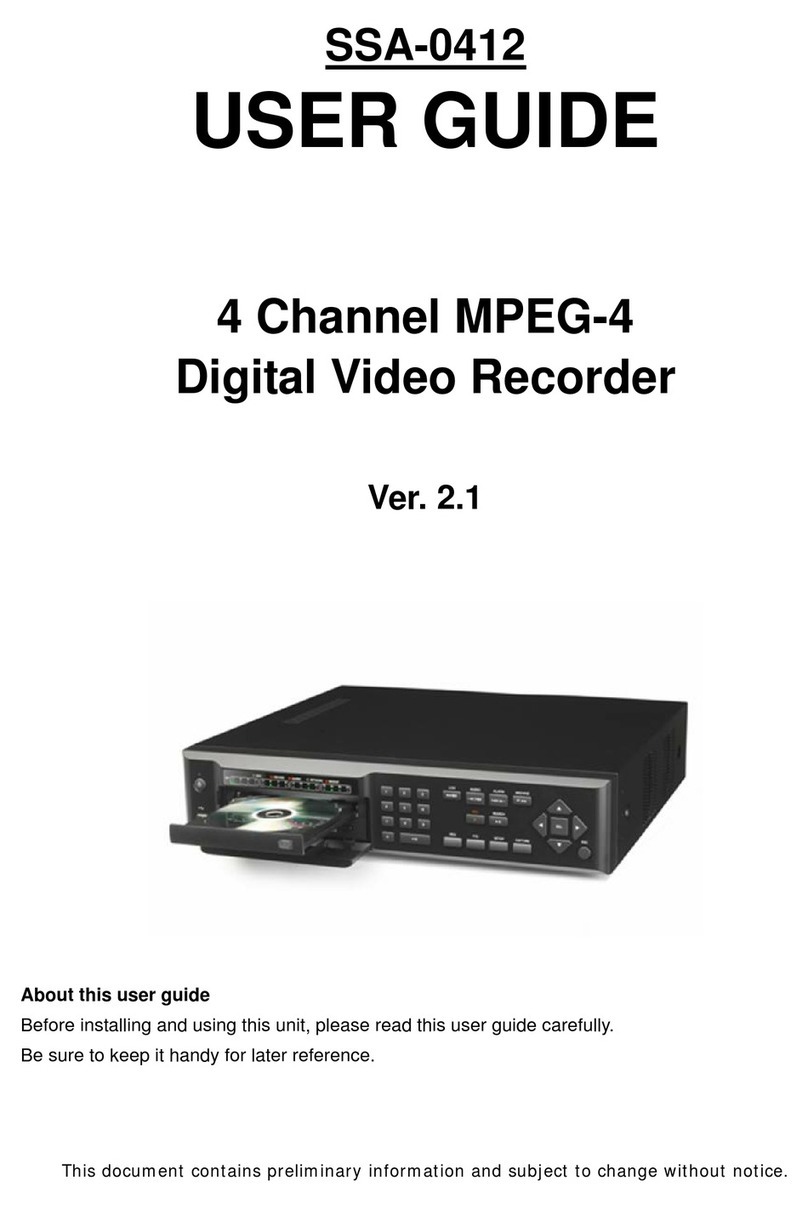
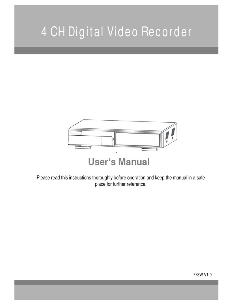
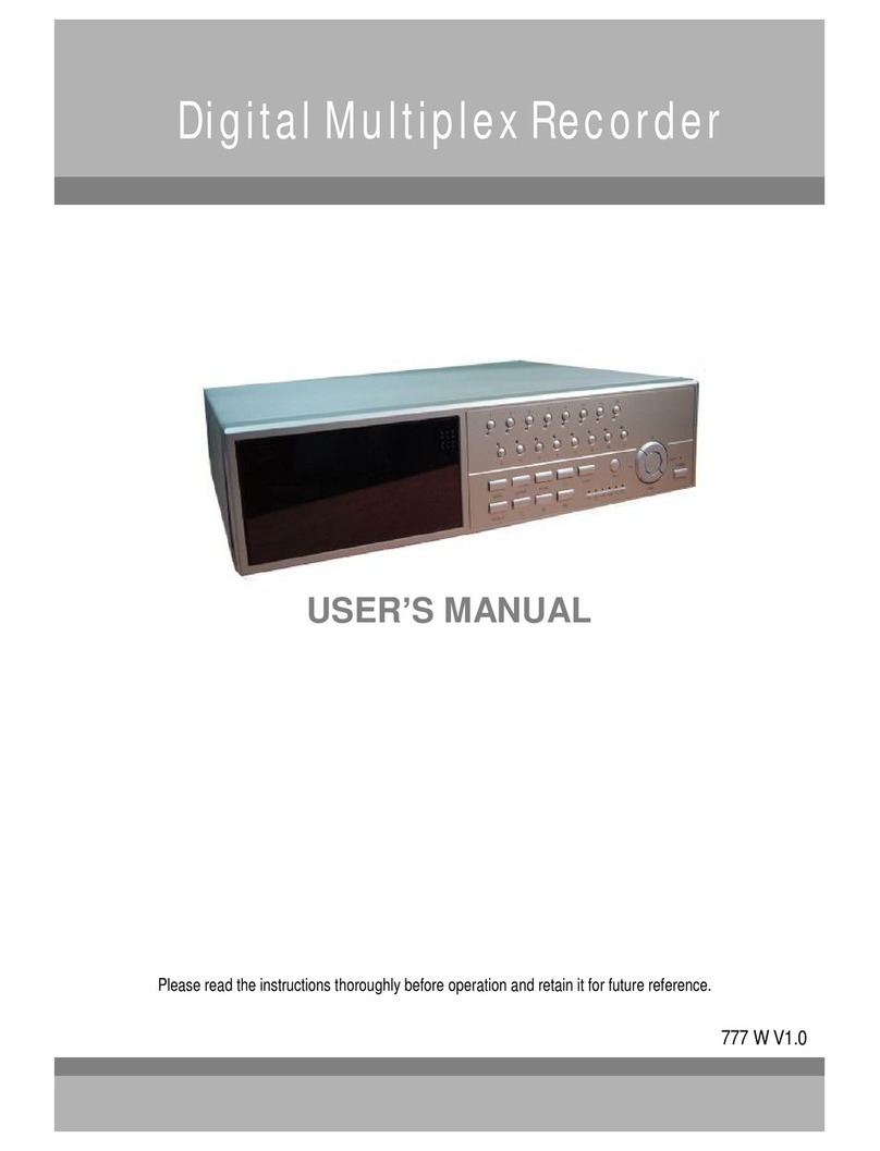
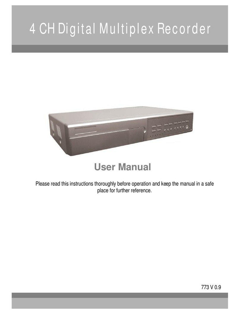
Maxtor 4 CH Digital Multiplex Recorder User manual

4CHDigitalVideoRecorder
User sManual
Pleasereadthisinstructionsthoroughlybeforeoperationandkeepthemanualinasafe
placeforfurtherreference.
771-A V 1.0

All thesafetyandoperating instructionsshouldbereadbeforeoperation.Theimproperoperation maycause
permanentdamage.
Thisadaptorisonlyforthismachine.Donotuseitfor otherelectronicproductsor itmaydamageotherproducts.
Pleaselift andplacethisequipment gently.
Donotexposethisequipmentfromdirectsunlightandkeepitawayfromsourcesofintenseheat.
Donotusethisequipmentnearwaterorincontactwithwater.
Avoiddustyorhumidplace.
DonotswitchthePowerOn&Offwithinshort period of time(within3seconds).
Donotblock theventilationholesatthetopandbottomoftheunit.
Donotattempttoservicethisequipmentbyyourself.
Installationshouldbemadebyqualifiedservicepersonnel.
Donot trytoretrievetheHDDdatabyPC.
Thelightningflashwitharrowheadsymbol, withinanequilateraltriangle, isintendedtoalert
theuser tothepresenceofuninsulated"dangerous voltage"withintheproduct'senclosurethat
maybeofsufficientmagnitudetoconstitutea riskofelectricshocktopersons.
Theexclamationpointwithinanequilateraltriangleisintendedtoalerttheuser tothepresence
ofimportantoperatingand maintenance-(servicing)instructionsintheliteratureaccompanying
theappliance.
WARNING
1

Whatdoyouget
Whatdoyouget ?
?
FEATURES----------------------------------------------------------------------------------------
PACKAGECONTENT --------------------------------------------------------------------------
BeforeOperation
BeforeOperation
INSTALLATIONGUIDE------------------------------------------------------------------------
FRONTPANEL -----------------------------------------------------------------------------------
REARPANEL-------------------------------------------------------------------------------------
Basic Operation
Basic Operation
GETTING STARTED------------------------------------------------------------------------------
OPERATION----------------------------------------------------------------------------------------
DetailedMenu Setup
DetailedMenu Setup
MAINMENU---------------------------------------------------------------------------------------
MENUOPTIONS---------------------------------------------------------------------------------
AdvancedOperation
AdvancedOperation
OPERATIONOPTIONS------------------------------------------------------------------------
KEYLOCK----------------------------------------------------------------------------------------
RS-232 PROTOCOL----------------------------------------------------------------------------
TROUBLESHOOTING---------------------------------------------------------------------------
SPECIFICATIONS---------------------------------------------------------------------------------
APPENDIX#1 –INSTALL THEHDD----------------------------------------------------------
APPENDIX#2 –REPLACETHEHDD--------------------------------------------------------
APPENDIX#3 –PINCONFIGURATIONS---------------------------------------------------
APPENDIX#4 –RECORDINGSPEED----------------------------------------------------------
APPENDIX#5 –NETWORK APPLICATION--------------------------------------------------
TABLEOFCONTENTS
3
3
4
5
7
8
8
10
10
16
17
17
17
18
19
19
20
22
23
2

FEATURES
DVR Features
Wavelet compressionformatreplacesTime-LapseVCR+Multiplexer/Quad
OnScreenDisplayandRemoteControlviaVideo Server&PC
Picture-in-picture(PIP)andPicture-on-Picture(POP) functioninlive
Alarminput&outputfunction
Videoloss detectedoneachchannel
Multiplexer&Quadrecordingmodeswitching
Recordingrateuptofull size30fields/sec. orQuad size240fields/sec.
Support1HDD,IDETYPE(over250 GB)
Multiplequick searchbydate/time,alarm,fulllist
Securitypasswordprotection
RS-232,RS-485communicationprotocol
Whatdo you get?
Warning:
1. Please check thepackagetomake surethatyou receive thecomplete components shown above.
2. Thisadaptor isDC19V 2A. Usercan find theadaptor forreplacementat acomputer shop iftheadaptor isbroken.
PACKAGE CONTENT
User’sManual
DigitalVideo Recorder
3
Accessoriespack PowerAdapterandCord
Accessoriespack

1.Connectcameras andmonitortotheDVR.
2.Shownbelowisanexampleof connectingthe DVRtoyourexistingObservation System.
3.InstallHDD(ThecompatibleHDDBrandsarelistedinthefollowingtable.)
Pleaserefer topage 19. Appendix#1forinstallationinstructions.
*The HDDmustbeinstalledbeforeturningontheDVR.IfHDDisnot installed,theDVRwouldfunctionasa4CHmultiplexer.
INSTALLATION GUIDE BeforeOperation
COMPATIBLE HARD DISK MODELS
4
ManufacturerModelCapacityRotation
HITACHIDeskstar180 GXP(120 GB)120GB7200 rpm
HITACHIDeskstar7K250, HDS722516VLAT20 160GB 7200 rpm
HITACHIDeskstar7K250, HDS722525VLAT80250GB7200 rpm
IBMDeskstar120GXP(80GB)80GB7200 rpm
IBMDeskstar120GXP(120GB)120GB7200 rpm
MaxtorDiamondMax536DX(60GB)4W060H460GB5400 rpm
MaxtorDiamondMaxPlus980GB7200 rpm
MaxtorDiamondMaxPlus9,Model#6Y120L120GB7200 rpm
MaxtorDiamondMaxPlus9,Model#6Y160L0160GB7200 rpm
Maxtor MaxLine Plus
Ⅱ
,Model#7Y250P0 250GB7200 rpm
SeagateBarracuda ATAIV,ST380021A80GB7200 rpm
SeagateBarracuda ATAV, ST3120023A120GB7200 rpm
SeagateBarracuda 7200.7 Plus,ST3160023A160GB7200 rpm
WesternDigitalCaviarWD1200BB-00CAA1120GB7200 rpm
WesternDigitalCaviarWD2000BB-00DWA0200GB7200 rpm
WesternDigitalCaviarSE WD2500JB250GB7200 rpm

FRONT PANEL
5
To slowdownthespeedofplayingmode.
SLOW
: Press “”buttonfor 4CHdisplaymodes
-:Press “-”buttoncanchangethe settinginthemenu.
/-4-channel display mode
PIP:Press “PIP”buttonforPictureinPicturescreen.
+: Press “+ ”button can changethesetting inthemenu.
/+Picture inPicture
Press “”buttonforPictureon Picturescreen.
/POP
Press SEARCH forsearchingrecordedvideo.
SEARCH
Press ENTERforconfirmation
ENTER
Press MENU toenter mainmenu.
MENU
The LEDLightisONunder followingcondition.
HDD :HDDisreadingorrecording.
HDD Full :HDDisfull
ALARM: Toturnoff theALARMLEDlight,pleaserefer topage.13and
settheALARMmodeasOFF.
TIMER: WhenTimerisEnabled
PLAY:Playing mode
REC:Recording mode
LEDLIGHT

6
DuringtheLIVEor PLAYmode,press both“ENTER”and“SEARCH”buttons
toswitchthe “NORMAL”or“SHARPNESS”display.(refer topage.9)
ENTER+SEARCH
Press theCameraSelect (1-4) toselectthechannel.
CAMERA SELECT(1-4)
Press REC tostart recording.
REC
Press PLAY toplayback recordedvideo.
PLAY
Pause:Under DVRplaymode,itcanpausetheaction.
:Undersetup mode,itworks asUpbutton.
PAUSE/
STOP:Under DVRRecord/ Playmode,it canstopthe
action.
▼:Undersetup mode,itworks asDownbutton.
STOP/ ▼
REW:Playvideofastbackward.(Press REWbutton
againtoadjust speedas1,2,4,8,16, 32times)
:Undersetupmode, it works asLeftbutton.
REW/
FF:Playvideofastforward.(Press FFbuttonagainto
adjustspeedfrom1,2,4,8,16,32times)
►:Undersetupmode, it works asRightbutton.
FF / ►

7
1. EXTERNALI/O
Controlledremotelybyan externaldeviceorcontrol systemlikeVideoWebServer.
Alarminput, externalI /Oexpansion.
2. VIDEOINPUT(1-4)
Connecttovideosource,suchascamera.
3. MAIN
ConnecttoMainmonitor.
4. CALL
ConnecttoCALLmonitor. ShowtheSwitchDisplay.
Whenalarmistriggered,thecallmonitor willshowthetriggeredchannelaccordingtothesystemsetting.
5. POWER
Pleaseusetheprovidedpowercord.
Warning:
1.Thisadaptor isonlyfor thismachine.Do notuse itfor other electronicproduct or itmay damageotherproducts.
2.Thisadaptor isDC19V 2A. User can find theadaptor forreplacementat acomputer shop iftheadaptor isbroken.
6. FAN (OPTIONAL)
Forventilation.
Note: Iftheambienttemperatureishigh or ambientventilation isbad, we suggest to install afanon therear panel.
REAR PANEL
DC19V
EXTERNALI/O
MAIN1423
IN
CALL
OUT
12 4 5
6

RECORDING
The DVRoffers3recordingmodes.ReferP.22 for advancedsettingofrecordingspeedand
resolution.Under therecordingstatus, if powerisoffaccidentally,recorded videowill stillbestored intheHDD. DVRwill
returntooriginalrecordingsettingafter powerrestoresagain.
Whileyoupress “REC”button,onthescreen, youwill findthedate,time, recordingtype,the
availableHDDspaceinGB andtheletter“”representstherecording mode.
(OW :HDDOverwrite)
NOTE:1. WhentheHDD isfullunderO/WRecordingmode,previousrecordedfiles will beoverwritten
withoutfurtherwarningnotices.
2. IftheHDD space isonly5GB left,itwilldisplay 5GB”on theup-rightscreenin
orangecolor,anditwillbuzz forseconds; soas in4GB, 3GB, 2GB and1GB.IftheO/W
Recordingmode(NOTE1) ison,itwon’thave thewarningbuzzer.
Thereare3recordingmodes:Alarm,TimerandManual Recording.
1. ALARMRECORDING
DVRistriggered byanalarm input. symbol willbeshownonthetriggered channel.(refer topage13)
2. TIMERRECORDING
RecordingisscheduledbyaTimer. Itwillindicatebythe symbol .(refer topage11)
3. MANUALRECORDING
RecordingisinitiatedmanuallybypressingtheRECbutton.Symbolwillbeshown.
1. ConnecttheAC powercordandplug intoan electrical outlet. ThePOWERLEDwillturnintoorangecolor,andother
red LEDindicatorswillturnON.It takesapproximately5to15secondstobootthesystemwiththe message:“HDD
Detecting ”.Oncesuccessfullyconnected,thePOWERLEDwill changetogreencolor, andtheAlarmLEDwillbeON.
BeforeusingtheDVR,pleasehaveaHDDinstalledready,or itwillfunctionas4CHmultiplexer(refer toAppendix#1for
installationorremovalofaHDD).
GETTING STARTED Basic Operation
OPERATION
2. BeforeoperatingtheDVR, setthesystemtimefirst. (refer topage.10).
NOTE :1.IftheHDD isnotinstalledcorrectlyornotinstalled,the HDD notfound”messagewill
appearfor3secondsandthenreturnto4CH Multiplexerdisplay mode.
2.Toswitchthesystem, pullouttheAC powercord,beforeyoureconnect thepower,
press FF”toNTSCsystemor REW”toPALsystem andthenreconnect theAC power
cord, theDVRwillauto-detectthesystem.
8
2002 –JAN –01 01:02:03
OW
(OW: HDDOverwrite)
PLAYBACK
Press “PLAY ”button, theDVR will showthe lastrecording.
1. FASTFORWARD (F.F.)&FASTREWIND (F.R.)
Youcanincreasethespeed ofFastForwardandRewindonthe DVR.
InthePlaymode,press “”oncetoget2Xspeedforwardand press twicetoget 4Xspeed,…andthemaximum
speedcan reach32X.
Press “◄”oncetoget1Xspeedrewindandpress twicetoget2Xspeed,…and themaximum speedcanreach
32X.
2. SLOWFORWARD (S.F.)& SLOWREWIND (S.R.)
Youcanalsoslowdownthe speedofForwardandRewind ontheDVR.
InthePlaymode,press theSLOWbuttonandyouwillenterSlowmode.
Press “SLOW ”oncetoget1/2Xspeedforwardandpress“”toget1/4Xspeed,…andtheslowestspeedcan
reach1/32X.
Press “◄”oncetoget1/2Xspeedrewindandpress twicetoget1/4X speed,…andtheslowestspeed canreach
1/32X.
3. PAUSE
Youcanpausethe playbackandtheimagewill bedisplayed onthe screen.
4. STOP
Press “STOP ”buttonunderanycircumstance,DVRwillreturntolivemonitoringmode.
5. IMAGE JOG DIAL
It willallowyoutomanuallyviewvideoframe-by-frame,oneimage atatime.
WhileinPLAYmode,press“PAUSE ”,it willpausethescreen.
Press “”buttonadvancesthefrozen screenoneimageforward.
Press “◄”buttonmovesback oneimage.
Note: DuringtheLIVE orPLAYmode,press both ENTER”andSEARCH”buttonstoswitchthe NORMAL”or
SHARPNESS”display.
CAMERASELECT(1-4)
Press CameraSelect(1-4)toselectthecameratodisplayinfull screen.
9

10
Thereare11optionsavailableintheMainMenu:
TIMER ----------Program Timer Recording
CAMERA -------CameraSetup
RECORD -------RecordingModeSetup
ALARM ---------Alarm Setup
DWELL ---------Dwell timeSetup
PIP ---------------PictureinPictureSetup
DISPLAY -------DisplayMode Setup
REMOTE -------RemoteControlSetup
USER -----------UserPasswordSetup
SYSTEM -------SystemSetup
EVENT ---------EventList
OutlinedbelowarethebuttonsusedforMenu setting:
”and ▼”:Scroll upanddownwithinamenuoption
◄”and ”:Scroll sidewayswithinamenuoption thathasbeenselected
+ ”and -”:Increaseanddecreasethenumberorchangevalueswhenan optionisselectedandisblinking
ENTER: Selectasubmenu/anoptionunderasubmenuforbrowsing/modification
MENU: Completemodification ofamenu option;exitamenu
MAINMENU
(MENU)
TIMER
CAMERA
RECORD
ALARM
DWELL
PIP
DISPLAY
REMOTE
USER
SYSTEM
EVENT
DetailedMenu Setup
(MENU)
TIMER
CAMERA
RECORD
ALARM
DWELL
PIP
DISPLAY
REMOTE
USER
SYSTEM
EVENT
MENUOPTIONS
SYSTEM
4. KEYMUTE
To settheKEY MUTE.Whenthe settingis“YES”,therewillbenosoundwhenyoupress anykey.
5. HDD OVERWRITE
TosettheHDDOVERWRITE.WhentheHDDisfullunderO/W recording mode,previouslyrecorded
fileswillbeoverwrittenwithoutfurther warningnoticeswhenthe HDDOVERWRITEisON.
1. BUZZER
Setthe BUZZ “ON”, it will buzz byeventoccurrence.
2. EXTALARM
TosettheEXTALARM. It willbe trigged byeventoccurrencewhen thesetting isON.
3. VLOSSALARM
To settheVLOSSALARM.When thesettingis“ON”,the alarm willstart bythesetting
ofBuzzer, EXTalarmorAlarmDuration.

11
(SYSTEM)
BUZZERON
EXT ALARMON
VLOSSALARMON
KEYMUTEYES
HDD OVERWRITEYES
MESSAGELATCHYES
DATEDISPLAYD/M/Y
DATE26-DEC-2003 [FRI]
TIME22:55:34
CLEARHDD YES
SYSTEMRESETYES
6.MESSAGE LATCH
To selectwhether theDVRmessageswilldisappearafter 10
secondsorremainon screen.NOisthedefault settingwhichthe
messageswill disappearafter10sec.
NOTE:Videoloss,andAlarm messageswillbeshown
the sameasAlarmDuration time.
7. DATEDISPLAY
To setthe dateY/M/D,M/D/Y,D/M/YandOFFonmonitorornot.
8. DATE
To setthe dateontheDVR.
9. TIME
To setthe timeonthe DVR.
10. CLEAR HDD
Deleteall thecontentsofthe HDD.Whenyouchoose“YES”onthisoption,press “ENTER”andyou
willbepromptedwiththequestionshown:Press“”toclear HDDorpress ”←”tocancel.
11. SYSTEMRESET
Resetallsystemtothefactorydefault settings.Select“YES”and press “ENTER”button.
TIMER
1. DAY
Selecttheday,or days oftheweek(Mon–Fri/ Sat-Sun/Daily) thatyouwishtoschedule
theDVRtoautomaticallyrecord.
NOTE :
1.Changethedateby “+”and “-”buttons.
2.If youhaveselectedthedateand Timer recordingsetfromthatspecificday
toanewday,thenthe Timer Recording Schedulewill be set as wholeweek.
For specificdateof Timer Recording Schedule,itisnotrecommendedtoset
EndingTimeover23:59.For example: If youset TimerScheduleDay asSunday,
andSTARTfrom 11:30,butEndon00:20,thenRecordingTimer Scheduleis
setas from everySunday's11:30tonext Sunday‘s00:20.If you onlywanttoset
RecordingTimer Schedulefrom everySunday11:30 toMonday00:20,thenyou
shouldsetRecording TimerScheduleas Sundayfrom11:30to23:59,andMonday
from00:00to00:20.
3.It isnotsuggestedthat userspress “STOP”buttonorrestartthesystemduringsetting
time.Indoing so, therecordingwillstop,anduserscanresumerecording by pressing
“ENTER”+ “MENU”.
(MENU)
TIMER
CAMERA
RECORD
ALARM
DWELL
PIP
DISPLAY
REMOTE
USER
SYSTEM
EVENT

2. START
Setthe timetostarttherecording.
3. END
Setthe timetoendtherecording.
4. IPS (IMAGESPERSECOND)
NTSC-30、15、8、4、2、1
PAL-25、12、6、3、2、1
5. QUALITY
Select thequalityof recordingimage:BEST, HIGH,NORM andBASE.
6. MODE
Therearethree recordingmodesettings:
QUAD-FRAME,QUAD-FIELD,MULTIPLEX.
NOTE:Toensurethebest recordingquality,we don’tsuggest
theusersswitchadifferentrecordingmodeduring
theperiodofrecording.
7. TIMER ENABLE
WhenTIMERENABLEis “YES”, press “menu”button,you
canseethetimerdiagramaccordingtoyoursetting.
(TIMER)
DAY STARTENDIPSQLT MODE
DAILY01:0022:0030BEST Q-FR
OFF 00:0000:0030BEST Q-FI
OFF 00:0000:0030BEST Q-FR
OFF 00:0000:0030BEST MUX
OFF 00:0000:0030BEST Q-FI
TIMERENABLE: YES
12
CAMERA
1. TITLE
Assign atitletoeachcamera. Initiallyeachtitleisthecamera’snumber.
(Max:8characters)
2. ALARM
SelectLOW /OFF/HIGH foralarmpolarity. The default valueisLOW.
(MENU)
TIMER
CAMERA
RECORD
ALARM
DWELL
PIP
DISPLAY
REMOTE
USER
SYSTEM
EVENT
TITLE
18
151518
ON
HIGH
CAMERA04
18
1515
18OFF
HIGH
CAMERA03
18
15
15
18
OFF
OFF
CAMERA02
181515
18
ON
LOW
CAMERA01
HUE
CLCT
BR
REC
ALARM (CAMERA)

(RECORD)
RECORD IPS30
QUALITYNORMAL
RECORD MODEQUAD-FRAME
13
3. REC(RECORD)
Setupwhichchannel youwanttorecord.
ON : when alarminputistriggered,DVR will recordalarmingchannelmorefrequently.
Forexample:whenCH01istriggered,therecordmethodwillbecome1-2-1-3-1-4….
OFF : DVR will notrecord.
4. BR (BRIGHTNESS)
Adjust thebrightnessofeachchannel. Thelevelisfrom0to63.
5. CT(CONTRAST)
Adjust thecontrastofeachchannel. Thelevel isfrom0to63.
6. CL(COLOR)
Adjust thecolor ofeachchannel. Thelevel isfrom 0to63.
7. HUE(HUE)
Adjust thehueofeachchannel. Thelevelisfrom0to63.
(MENU)
TIMER
CAMERA
RECORD
ALARM
DWELL
PIP
DISPLAY
REMOTE
USER
SYSTEM
EVENT
RECORD
1. RECORD IPS
Select therecordingspeed.Theoptionsare
asfollowing:
NTSC-30、15、8、4、2、1
PAL-25、12、6、3、2、1
2. QUALITY
Therearefourqualitysettings:BEST,HIGH, NORMAL,BASIC.
NOTE:TherelationshipofRecordtime, IPSandRecordquality,
please refertopage.22 RecordingSpeed.
3. RECORD MODE
Therearethree recordingsettings:QUAD-FRAME,QUAD-FIELD,
MULTIPLEX.
ALARM
1. ALARMENABLE
Alarmwillbetriggeredbyeventoccurrencewhenthesettingis
YES.
2. ALARMDURATION
Setthe reactiontimeofthealarmmoderespondstoabuzzer.
Default settingis10Sec.Optionsare10Sec,15Sec,20Sec,
30Sec,1MIN,2MIN,3MIN,5MIN, 10MIN,15MIN,30MIN,
ALWAYS,AUTO.
NOTE:1. Videoloss, and Alarmmessages will beshownthesame as AlarmDuration time.
2. Whenthesetting isAUTO, thealarmduration time isaccordingto thesetting ofthe
externalalarmdevice.
3. During ALARM DURATION’Ssetting time, userscanrestartALARM function by
pressing both ENTER”+ STOP”buttons.
(MENU)
TIMER
CAMERA
RECORD
ALARM
DWELL
PIP
DISPLAY
REMOTE
USER
SYSTEM
EVENT

(DWELL)
NORMALARM
CAM10101
CAM20101
CAM30101
CAM40101
3. REC IPS
Select theimagespersecondofrecordingduringanALARM.Theoptionsareasfollowing:
NTSC-30、15、8、4、2、1
PAL-25、12、6、3、2、1
4. QUALITY
TherearefourrecordingqualitysettingsduringanALARM:
BASIC,BEST,HIGH,NORMAL.
5. RECORD MODE
Therearethree recordingsettings:QUAD-FRAME,QUAD-FIELD,
MULTIPLEX.
(ALARM)
ALARMENABLEYES
ALARMDURATION15MIN
RECORD IPS30
QUALITYNORMAL
RECORD MODEQUAD-FRAME
DWELL
1. NORM
TosetuptheDWELLtimeperiodthateachchannelautosequentiallyshowsoncall
monitor. Thelevelisfrom1to15Secor OFF.
2. ALARM
TosetuptheDWELLtimeperiodwhenalarm inputistriggered.The levelisfrom1to
15Secor OFF.
(MENU)
TIMER
CAMERA
RECORD
ALARM
DWELL
PIP
DISPLAY
REMOTE
USER
SYSTEM
EVENT
PIP
1. FULL SCREEN
Tosetupthefull screenbackgroundpicturedisplay.
2. PIPSCREEN
Tosetupthepicturewitha1/9sizescreen“insert”.
3. POSITION
Therearesixpositionsettings:D/L, D/M,D/R,U/L,U/M,U/R.
(MENU)
TIMER
CAMERA
RECORD
ALARM
DWELL
PIP
DISPLAY
REMOTE
USER
SYSTEM
EVENT
(PIP)
FULL SCREENCAM1
PIPSCREENCAM 2
POSITIOND/R
14
DISPLAY
1. TITLE DISPLAY
Tosetthetitleshown onmonitorornot.
2. OSDCOLOR
Select theOSD(OnScreenDisplay)color. Theoptionsare
YELLOW,GREEN, CYAN,BLUE,PINK,GRAY,WHITE, RED.

(MENU)
TIMER
CAMERA
RECORD
ALARM
DWELL
PIP
DISPLAY
REMOTE
USER
SYSTEM
EVENT
(MENU)
TIMER
CAMERA
RECORD
ALARM
DWELL
PIP
DISPLAY
REMOTE
USER
SYSTEM
EVENT
REMOTE
1. REMOTEMODE
Setthe remotemodeforconnectionwithcomputerviaRS-232orRS-485.
(Pleaserefer topage.20&21for RS-232&RS-485RemoteControl).
2. BAUD RATE
Setthe remoteprotocoltransmittingbaudrate. Availableoptionsare115200,
57600,19200,9600,4800,3600,2400,1200.
3. ID
To control differentDVRbysetting
remoteprotocol.IDnumbercanbeset
from000to255. (REMOTE)
REMOTEMODERS-485
BAUD RATE9600
ID255
USER
1. USER
Tosetuptheuseraccountforcontrolling.It
allows8userssetting.
Supervisor –Controlall thefunctions.
OtherUsers –Viewallfunctionsexcept the
menusetting.
2. PASSWORD
Tosetthesecuritypasswordfor eachaccount.
The maximumlengthofuser’spasswordis4
characters.
NOTE:ToswitchtodifferentUSER, press
ENTER”+ MENU”buttonsto KEY
LOCK”andthenenterthedifferentuser’s
passwordtoUNLOCK.
(USER)
PASSWORD
SUPERVISOR0000
USER 10000
USER 20000
USER 30000
USER 40000
USER 50000
USER 60000
USER 70000
15
(DISPLAY)
TITLEDISPLAYYES
OSDCOLORYELLOW
LOSSSCREENGREEN
TIMEPOSITIONNORMAL
3. LOSSSCREEN
RetainthelastpictureorselecttheLOSSSCREENcolor.
The optionsareGREEN, BLACK,BLUEand RETAIN.
4. TIMEPOSITION
Toset theOSD POSITIONshownonmonitor.
TheoptionsareNORMALor CENTER.
(MENU)
TIMER
CAMERA
RECORD
ALARM
DWELL
PIP
DISPLAY
REMOTE
USER
SYSTEM
EVENT

(MENU)
TIMER
CAMERA
RECORD
ALARM
DWELL
PIP
DISPLAY
REMOTE
USER
SYSTEM
EVENT
16
EVENT
C1 VLOSS26-DEC-200203:00:00
C2 ALARM26-DEC-2002 03:00:00
KUNLOCKS26-DEC-200203:00:00
M-HD ERR 26-DEC-2002 03:00:00
M-HD WARM26-DEC-200203:00:00
PWRREST26-DEC-200203:00:00
DMA ERROR26-DEC-2002 03:00:00
M-HD REPL26-DEC-200203:00:00
↑+↓: CLEAR
Asinglepagecan display16recordedevents.Press“◄”or “”tochangethe
pagesor press “▲”+ “▼”toCLEAR theEVENTrecord.
DISKFULL:HDD isfull
PWRREST : Powerrestored
M-HDREMS:HDDremoval
M-HDREPL:HDDreplace
M-HDERR: HDDerror
M-HDWARM:HDDwarning
KUNLOCKS: Keyisunlock
DMAERROR:DMAerror(Direct MemoryAccess)
C1 VLOSS: VideolossonCh1
C2 ALARM: Channel 2hasbeentriggered byexternalI/Oalarm
SYSTEMERROR:Systemfail
POWERRESTORE: Powerrestored
VIDEOLOSS
Screen will display “VLOSS”inthecenter ofdisplaypicture,ifthevideo inputisnotconnectedproperly.
SEARCH
1. LASTRECORD
Playthelastrecorded pieceof video.
2. FULL LIST
Listall recordedvideo ontheHDDwhichsorted bytime.
3. ALARMLIST
Listall recordedvideo triggeredbyAlarm.
NOTE: IftherearenoAlarmintherecord,thescreenwill
display “EMPTY”.
4. TIMESEARCH
Enter thespecifictime/date.
OPERATIONOPTIONS
LAST RECORD
FULLLIST
ALARMLIST
TIMESEARCH
2003-JAN-01 01:02:03 M
2003-JAN-05 05:02:03 M
2003-MAR-12 04:02:03M
2003-APR-02 03:02:04M
2003-MAY-0105:02:03 M
2003-AUG-0901:02:01 M
:PAGEUP→:PAGEDOWN
:ManualRecording
:AlarmRecording
:Timer Recording
M:StorageinMasterHDD
S:StorageinSlaveHDD
NOTE: Itwilldisplaydifferentcoloroneachrecordlist
mentionabove.
Advanced Operation

RS-232REMOTE PROTOCOL
17
KEY LOCK
Foradvancedsecurity,youcan“Lock”thebuttonsonyourDVR.Key-Lock preventsotherpeoplefromusingthesystem.
Press ENTERand MENU at thesametimetoenableKeyLock.
Press ENTERand MENU at thesametimeandkeyinpassword(Default:0000), thenpress“ENTER“todisableKeyLock.
NOTE:ToswitchtodifferentUSER,press ENTER”+ MENU”buttonsto KEYLOCK”andthenenterthedifferentuser’s
passwordtoUNLOCK.
You canusethePCkeyboardtosimulateDVRkeypad.
DATA: REMOTE PROTOCOLusing8bitdata、1start bit、1stopbit
FUNCTIONCODEASCIIFUNCTIONCODEASCII
KEY_MENU0x4DMKEY_PLAY0x50P
KEY_SEARCH0x73sKEY_DOWN0x4EN
KEY_ENTER0x0DENTERKEY_RIGHT0x52R
KEY_QUAD0x51QKEY_KEY_LOCK0x4BK
KEY_POP0x5AZKEY_CH10x311
KEY_PIP0x70pKEY_CH20x322
KEY_SLOW0x53SKEY_CH30x333
KEY_REC0x72rKEY_CH40x344
KEY_LEFT0x4CL
TIMERRECPROCEED
0X54T
KEY_UP0x55U
TROUBLESHOOTING
Whenmalfunctionoccurs,itmaynotbeseriousandcanbecorrectedeasily.Thefollowingtabledescribesthemost
commonproblemswiththeirsolutions.Pleasereadthoroughlybeforecallingyour DVRdealer.
PROBLEMSOLUTION
l
Checkpowercordconnections.
l
Confirmthatthereispowerat theoutlet.
l
Checkifit isunderKeyLock mode.
l
Press "MENU" &"ENTER" toexistKeyLock mode.
Norecordedvideo l
CheckiftheHDD isinstalled properly.
TimerRecordenabledoesnot
working l
CheckiftheTimeEnableisset toYES
l
Checkcameravideo cableand connections.
l
Checkmonitorvideo cableand connections.
l
Confirmthatthecamerahaspower.
l
Checkcameralenssetting.
Nolivevideo
Nopower
Notworkingwhenpress any
button
Toswitchthesystem, press “FF”toNTSCsystemand
“REW”toPALsystem.(RefertoPage 8"Getting Started").
NTSC&PALSystem switch

Videoformat NTSC/EIA orPAL/CCIR
Hard diskstorage IDE type, UDMA66, supported250GB HDD
Record mode Manual / Alarm/ Timer
Camera Input Signal Compositevideosignal 1Vp-p75ΩBNC, 4channels
Main Monitor Output Compositevideosignal 1Vp-p75ΩBNC
Call MonitorOutput Compositevideosignal 1Vp-p75ΩBNC
VideoLossDetection Yes
RefreshRate Up to240fields/sec. forNTSC/ 200fields/sec. forPAL
Recording Rate Multiplex: Up to30fields/sec. for NTSC/ 25fields/sec. for PAL
Quad-field: Upto120fields/sec. for NTSC/ 100fields/sec. forPAL*
Quad-frame: Upto240fields/sec. for NTSC/ 200fields/sec. forPAL**
DwellTime Programmable(1~15Sec)
PictureinPicture Yes (Movable)
KeyLock Yes
Camera Title 8letters
VideoAdjustable Hue/ Color/ Contrast/ BrightnessAdjustable
Alarm Input TTLinput, Hi(5V), Low (GND)
Alarm Output COM./N.O/N.C
RemoteControl RS-232orRS-485
Time DisplayFormat YY/MM/DD, DD/MM/YY, MM/DD/YY, OFF
PowerSource DC 19V
PowerConsumption <32W
Operation Temperature 10~40℃
RS-232C / RS-485(bps) 115200、57600、19200、9600、4800、3600、2400、1200
Dimension(mm) 343(W)x223(L)x59(H)
NetWeight 1.5kgs
SPECIFICATIONS
18
Specificationsaresubjecttochange withoutnotice.
*NTSC:4CHx30IPS =120 fields/sec,PAL: 4CHx25IPS =100fields/sec
**NTSC:4CHx60IPS=240fields/sec,PAL:4CHx50IPS=200fields/sec

Followthesestepscarefullyinordertoensurecorrect installation.
19
APPENDIX #1 INSTALL THE HDD
Step1Removethelidand unscrewthe screwsfromHDD bracket module.
Step2InserttheHDD intotheHDD bracket andscrew thefourscrews.
The bottomsideispowerside aschart shows(refertotheFig1).
Step3Connect the HDD powercabletotheHDD (refertotheFig. 2).
Step4Attachthe HDD connectortothe 40-pinpinhead, andscrewthe HDD and
the DVRmachinetogether(refertotheFig. 3).
Step5 Pullthesidesof the lid apart slightlyandpushthe liddown.
Note: DonottrytoretrievetheHDD data byPC. ThevideofilecannotbereadbyPC,
operationonPCwoulddamagetheFATtableoftheharddisk.
Step1Removethelid.
Step2 Unscrewthe screwsand takeouttheHDD fromDVRmachinecarefully
(refertotheFig3).
Step3RemovetheHDD powercablefromthe HDD (refertotheFig.2).
Step4Unscrewthe fourscrewsconnected theharddrivetothebracketand removethe
HDD bracket module.Repeatthosestepsaccording tothe “Installthe HDD”section for
resettinganotherHDD (refertotheFig1).
Step5Pullthesidesof the lid apart slightlyandpushthe liddown.
Note:WhenHDD worksforaperiodoftime,thesurface temperaturewill behigh, please notice it.
APPENDIX #2 REPLACETHE HDD
Followthesestepscarefullyinordertoensurecorrect installation.
Fig.1Fig.2Fig.3
HDDPower CableHDDPower Cable
HDDBracket
Other manuals for 4 CH Digital Multiplex Recorder
1
Table of contents
Other Maxtor DVR manuals

Maxtor
Maxtor CDR-04S User manual

Maxtor
Maxtor Built in Digital Video Recorder User manual

Maxtor
Maxtor 16 Channel Digital Video Recorder User manual

Maxtor
Maxtor 4-Channel DVR (Digital Video Recorder) User manual

Maxtor
Maxtor DVMR User manual

Maxtor
Maxtor 4Channel Stand-alone DVMR User manual

Maxtor
Maxtor 773W V1.0 User manual

Maxtor
Maxtor 16Channel Stand Alone DVR User manual

Maxtor
Maxtor pmn User manual

Maxtor
Maxtor AVE MVDR-5000 User manual