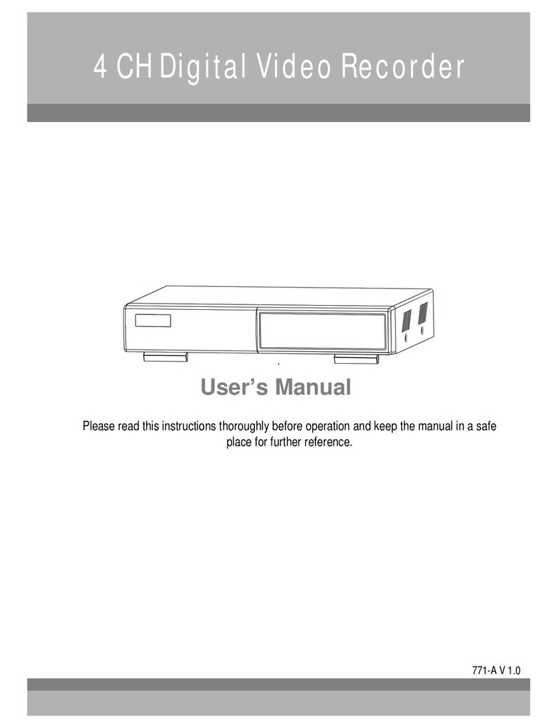
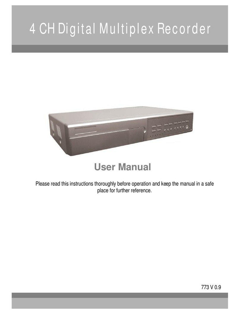
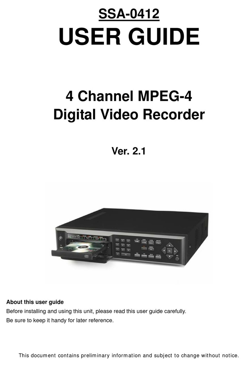
Maxtor 773W V1.0 User manual

4CHDigitalVideoRecorder
User sManual
773WV1.0
Please read this instructionsthoroughly before operation and keep the manualin a safe
place forfurtherreference.

Thelightning flashwitharrowheadsymbol,withinanequilateral
triangle, isintendedtoalert theusertothepresenceofuninsulated
"dangerousvoltage" withintheproduct'senclosurethat maybeof
sufficient magnitudetoconstitutearisk of electricshock topersons.
Thisadaptorisonlyforthismachine.
Donot useit forotherelectronicproductsoritwilldamage otherproducts.
Pleaselift andplacethisequipment gently.
Donot exposethisequipmenttodirectsunlight.
Donot usethisequipmentnearwaterorin contact withwater.
Donotspillliquid ofanykind on the equipment.
Pleasepowerdownthe unit beforeunplugging.
Donot block the ventilationholesat thetop andbottomof theunit.
DonotswitchthePowerOn&Off within shortperiod of time
(within 3seconds).
Installation should be made byqualified servicepersonnel.
All thesafetyand operating instructionsshouldbereadbeforeoperation.
Improperoperationsmay cause permanent damage.
Theexclamation pointwithinanequilateraltriangleisintendedtoalertthe
usertothepresenceof importantoperatingandmaintenance-(servicing)
instructionsinthe literatureaccompanying theappliance.
WARNING

Whatdoyouget ?
FEATURES ---------------------------------------------------------------------------------------
PACKAGECONTENT -------------------------------------------------------------------------
BeforeOperation
INSTALLATIONGUIDE ------------------------------------------------------------------------
FRONTPANEL ------------------------------------------------------------------------------------
REAR PANEL -------------------------------------------------------------------------------------
BasicOperation
GETTINGSTARTED -----------------------------------------------------------------------------
OPERATION ---------------------------------------------------------------------------------------
DetailedMenuSetup
MAINMENU---------------------------------------------------------------------------------------
MENUOPTIONS ---------------------------------------------------------------------------------
Networksettingguide
HARDWARECONNECTIONATSERVERSITE-------------------------------------------
STATICIPSETTING ------------------------------------------------------------------------------
DYNAMICIPSETTING ----------------------------------------------------------------------------
SOFTWAREOPERATIONATCLIENTSITE -----------------------------------------------
PLAYBACK OPERATION -----------------------------------------------------------------------
ADVANCESETTING -----------------------------------------------------------------------------
CONNECTVIDEOWEBSERVERVIAIEBROWSER -----------------------------------
AdvancedOperation
OPERATIONOPTIONS ------------------------------------------------------------------------
KEY LOCK ----------------------------------------------------------------------------------------
TROUBLESHOOTING ---------------------------------------------------------------------------
SPECIFICATIONS --------------------------------------------------------------------------------
APPENDIX#1 INSTALL THEHDD -----------------------------------------------------------
APPENDIX#2 REPLACETHEHDD ---------------------------------------------------------
APPENDIX#3 PINCONFIGURATIONS ----------------------------------------------------
APPENDIX#4 RECORDINGSPEED ---------------------------------------------------------
TABLEOFCONTENTS
1
1
2
3
5
6
6
8
8
17
18
22
34
36
37
40
42
43
43
44
45
46
47
49

FEATURES
DVRFeatures
Remotecontrol via internet
Waveletcompression formatreplacesTime-LapseVCR + Multiplexer/ Quad
4audio inputs/ 2audiooutputs
OnScreen Displayand RemoteControlvia PC
Connectvideo webservervia IEbrowser
Autosending message bye-mailorFTPwhen therehavealarm.
Autorecording when therehavealarm.
Picture-in-Picture(PIP)and Picture-on-Picture(POP)function in live,LinearZoom(2x~4x)
Motion detection&motion triggerrecording function (16*12detection point)
Alarminput&output function(COM/ NO/ NC )
Recording rateup tofull size30 fields/sec. orquad size240 fields/sec.
Multiple quicksearchbydate/time/alarm/full/motion list
Support IDEHDD capacitymorethan 400G.
Securitypasswordprotection
PACKAGECONTENT
1
Warning:
1. Please check thepackagetomake surethatyou receive thecompleteaccessories whichincludes thecomponentsshownabove.
2.ThisadaptorissuitedforDC19V2Ause.Ifitisdamaged,userscanfindreplacementadaptoreasilyinthelocalitywiththis
specification.
Accessoriespack PowerAdapterand Cord
Accessoriespack
2Keys
User’sManualDigitalVideoRecorder(withHDD cartridge)
CD-ROM
What doyou get?

1. Connectcameras and monitorto theDVR.
2. Shownbelowisanexampleof connecting theDVRto yourexisting Observation System.
3. Install HDD (ThecompatibleHDD brandsarelistedinthefollowing table.)
Pleaserefertopage.45Appendix#1forinstallation instructions.
Note:TheHDDmustbeinstalledbeforeturningontheDVR.IfHDD isnotinstalled, theDVRwouldfunctionas a4CH multiplexer.
INSTALLATIONGUIDE
COMPATIBLEHARD DISKMODELS
2
NOTE:Fornon-stop long-timerecording, wesuggesthaving twoHDDforrecording toensuregood reliabilityofHDD.
Manufacturer Model Capacity Rotation
HITACHI Deskstar180GXP(120GB) 120GB 7200 rpm
HITACHI Deskstar7K250, HDS722516VLAT20 160GB 7200 rpm
HITACHI Deskstar7K250, HDS722525VLAT80 250GB 7200 rpm
HITACHI Deskstar7K400, HDS724040KLAT80 400GB 7200 rpm
IBM Deskstar120GXP(80GB) 80GB 7200 rpm
IBM Deskstar120GXP(120GB) 120GB 7200 rpm
Maxtor DiamondMax536DX(60GB)4W060H4 60GB 5400 rpm
Maxtor DiamondMaxPlus9 80GB 7200 rpm
Maxtor DiamondMaxPlus9, Model#6Y120L 120GB 7200 rpm
Maxtor DiamondMaxPlus9, Model#6Y160L0 160GB 7200 rpm
Maxtor MaxLine Plus Ⅱ, Model#7Y250P0 250GB 7200 rpm
Seagate BarracudaATAIV,ST380021A 80GB 7200 rpm
Seagate BarracudaATAV, ST3120023A 120GB 7200 rpm
Seagate Barracuda7200.7Plus, ST3160023A 160GB 7200 rpm
WesternDigital CaviarWD1200BB-00CAA1 120GB 7200 rpm
WesternDigital CaviarWD2000BB-00DWA0 200GB 7200 rpm
BeforeOperation

/+ PICTUREINPICTURE
Press “ ” button for4CH displaymodesand press twicetoenter
POP(PictureOnPicture)function.
-: Press “-”button canchange the setting inthe menu.
FRONTPANEL
3
1 2
PressPowertoturnON/ OFF the DVR.
POWER
SLOW
PIP: Press “ ” button forPictureinPicturescreen.
+: Press“+”button canchange the setting in the menu.
Press ZOOMbuttontoenlarge the picturedisplay.
ZOOM
PressSEARCH button forsearching recorded video.
SEARCH
PressENTER button forconfirmation.
ENTER
Press MENU buttontoentermainmenu.
MENU
The LEDLightisONunderthefollowing conditions.
HDD : HDD isreading orrecording.
HDD Full: HDD isfull
ALARM: Toturnoff theALARMLEDlight, pleasereferto
page.12and setthe ALARMmode asOFF.
TIMER: When TimerisEnabled
PLAY : Playingmode
REC: Recording mode
2. CONTROLPANEL
LEDLIGHT
Toslowdownthespeed of playing mode.
1. REMOVABLEHDD CARTRIDGE
&KEYHOLE Pleaserefertopage.44Appendix#2.
/-4CHANNELSDISPLAYMODE

4
FF:Playvideofast forward. (PressFF button againtoadjustspeed
as1,2, 4, 8,16, 32times)
: Undersetupmode,it worksasRightbutton.
FF /
REW/ ◄REW:Playvideofast backward. (PressREWbutton again toadjust
speed as1,2, 4, 8,16, 32times)
◄: Undersetupmode,it works asLeftbutton.
STOP/ STOP: UnderDVRRecording/ Playing mode,it can stop theaction.
: Undersetup mode, it worksasDownbutton.
PAUSE / ▲Pause: UnderDVRplaying mode, itcanmakethe action pause.
▲: Undersetup mode, it worksasUpbutton.
PLAY Press “PLAY”button toplayback recorded video.
REC Press “REC”tostart recording.
CAMERA SELECT(1-4) PresstheCameraSelect (1-4)toselectthe camera.

1. LAN
Connect DVRby LANcable.
2. EXTERNAL I/O
Controlled remotelybyan externaldeviceorcontrolsystemsuchasVideoWeb ServerorPC.
Alarminput, externalI / Oexpansion.
3. VIDEOINPUT (1-4)
Connect tovideo source,suchascamera.
4. CALL
Connect toCALLmonitor. Showthe SwitchDisplay.
When the alarmistriggered, the callmonitorwillshowthetriggeredchannelforaperiod of time.
5. MAIN
Connect toMain monitor.
6. AUDIOIN(1-4)
Connect toaudiosources,suchasamicrophone.
IPS shouldbesetto30 (forNTSC)or25 (forPAL)
*4audioinputs, butcanonlyrecordoneinputatthesametime.
7. AUDIOOUT
Connect tomonitororspeaker.
IPS shouldbesetto30 (forNTSC)or25 (forPAL)
*with2monoaudiooutputsfrom thesamesource.
8. FAN
Forventilation, do not blocktheopening.
9. POWER
Pleaseusethe providedpowercord.
Warning:
1. Thisadaptorisonlyforthismachine. Donotuse itforotherelectronicproductoritwilldamageotherproducts.
2. ThisadaptorissuitedforDC19V2Ause Ifitisdamaged, usercanfind replacementadaptoreasilyinthelocalitywiththis
specification.
5
REARPANEL

RECORDING
The DVRoffers4recordingmodes,varietyof recording modes. Refertop.11 foradvanced setting of recording speedand
resolution.Underthe recording status,ifpowerisoff accidentally,therecordedvideo will still be stored inthe HDD.And
the DVRwillreturntooriginalrecordingsettingafterthe powerrestoresagain.
Onthe screen, you willfindthe date, time, HDD recordingtype,theavailablespaceof HDD (in GB)leftand thesymbol
“ ” representsthe recording mode.
NOTE:1. UnderO/Wrecording mode,previouslyrecordedfiles will be
automaticallyoverwrittenwithout furtherwarning notices, whenthe
HDD isfull.
2. IftheHDD capacityisonly5GBleft, itwilldisplay “5GB”on theup-right
screenandshowsorangecolor,and itwill buzz forseconds;soas in4GB, 3GB, 2GBand 1GB. Ifthe
O/WRecording mode(NOTE1)ison, itwon’thave thewarning buzzer.
Thereare4recording modes:Alarm, Motion, Timerand ManualRecording.
1. ALARMRECORDING
DVRistriggeredbyan alarminput. symbol willbeshownon the triggered channel. (refertopage12)
2. MOTIONTRIGGERRECORDING
Recordingistriggered bymotion detection.symbol willbe shownon the triggered channel. (refertopage13)
3. TIMERRECORDING
Recordingisscheduled byaTimer. It will indicatebythesymbol. (refertopage9)
4. MANUALRECORDING
Recordingisinitiatedmanuallybypressing theRECbutton.Symbol will beshown.
Connect the ACpowercordand plugintoan electrical outlet. The Red LEDindicatorlight willbe ONand the DVRis
in standbymode.
1.
PressthePowerbutton. The POWERLEDwillturnfromredtoorange, and otherred LEDindicatorswillturnON. It
takesapproximately5to15secondstoboot the system withthemessage : “HDD Detecting ”. Onceconnected, the
POWERLEDwill change togreen color, and the AlarmLEDwill beON.
2.
Beforeusing theDVR, pleasehaveaHDD installed ready,oritwillfunction as4CH multiplexer(refertoAppendix#1and
Appendix#2forinstallationorremovalof aHDD).
GETTINGSTARTED
OPERATION
2002 –JAN –0101:02:03
OW
3. Beforeoperating theDVR, setsthe systemtimefirst.(refertopage.9).
NOTE:1.IftheHDD isnotinstalledcorrectlyornotinstalled,the “HDDnotfound”messagewill appear for3seconds
and thenreturnto4CHMultiplexerdisplaymode.
2.To switchthesystem, you needtoturnoffthepowerand pull outtheACpowercordbefore reconnecting the
power.Andafterpressing “POWER”+ “FF”toNTSCsystemor “POWER”+ “REW”toPALsystemand
reconnecttheACpowercord, thesystem oftheDVRwill beswitched.
6
(OW: HDD Overwrite)
BasicOperation
PLAYBACK
Press “PLAY ”button, the DVRwill showthe lastrecording.
1. FAST FORWARD(F.F.)&FAST REWIND(F.R.)
You can increasethespeed of Fast Forwardand Rewind onthe DVR.
InthePlaymode, press “”oncetoget2Xspeed forwardand presstwicetoget 4Xspeed,…and themaximum
speed can reach32X.
Press “◄”oncetoget 1Xspeed rewind and presstwicetoget 2Xspeed, …and the maximum speed can reach
32X.
2. SLOWFORWARD(S.F.)&SLOWREWIND(S.R.)
You can alsoslowdownthe speed of ForwardandRewind on the DVR.
Inthe Playmode, pressthe SLOWbutton and youwill enterSlowmode.
Press ”SLOW ”oncetoget 1/2Xspeed forwardand press “”toget 1/4Xspeed,…and the slowestspeedcan
reach1/32X.
Press “◄”oncetoget 1/2Xspeed rewind and presstwicetoget1/4Xspeed, …and the slowestspeedcanreach
1/32X.
3. PAUSE
You can makethe playbackpauseand the image willbe displayedon the screen.
4. STOP
Press “STOP ”button underanycircumstance, the DVRwillreturntolivemonitoringmode.
5. IMAGEJOG DIAL
It will allowyou tomanuallyviewvideo frame-by-frame, oneimageat atime.
While in PLAY mode, press “PAUSE ”, andthe screen willpause.
Press “”button advancesthefrozen screen one image forward.
Press “◄”button movesback one image.
Note:During theLIVE orPLAYmode, press “ENTER”+ “SEARCH”buttonsatthesametimetoswitchthe “NORMAL”and
“SHARPNESS”display.
6. SHARPNESS
When in playmode,press “ENTER+ SEARCH”toswitchthe sharpness(normal orsharpness)
CAMERASELECT(1-4)
PressCameraSelect (1-4)toselect thecameratodisplayin fullscreen.
7

8
Thereare12 optionsavailableinthe Main Menu:
TIMER ----------Program TimerRecording
CAMERA -------CameraSetup
RECORD -------Recording ModeSetup
ALARM ---------AlarmSetup
DWELL ---------DwelltimeSetup
PIP ---------------Picturein PictureSetup
MOTION --------MotionDetectionSetup
DISPLAY -------DisplayModeSetup
NETWORK -----NetworkSetup
USER -----------UserPasswordSetup
SYSTEM-------SystemSetup
EVENT ---------EventList
Outlined belowarethe buttonsused forMenu setting :
“▲”and “”:Scrollup and downwithinamenu option.
“◄”and “”:Scrollsidewayswithin amenu option that hasbeen selected.
“+ ”and “-”:Increaseand decreasethe numberorchange valueswhenan optionisselectedand isblinking.
ENTER: Select asubmenu / anoption underasubmenuforbrowsing/ modification.
MENU : Completemodification of amenu option;exit amenu.
MAINMENU
(MENU)
TIMER
CAMERA
RECORD
ALARM
DWELL
PIP
MOTION
DISPLAY
NETWORK
USER
SYSTEM
EVENT
MENUOPTIONS
SYSTEM
1. AUDIOINPUT
Tochooseone of 4channelstorecord.(It canonlyrecord1inputat thesametime)
2. BUZZER
Set theBUZZER “ON”,it will buzzerbyevent occurrencewhenthesetting isON.
3. EXTALARM
Toset theEXTALARM. It willbe triggedbyevent occurrencewhenthe setting isON.
4. VLOSSALARM
Toset theVLOSS ALARM. Whenthe setting is “ON”, the alarmwillstart bythe setting
of Buzzer, EXTalarmorAlarmDuration.
5. MOTIONALARM
Toset theMOTIONALARM.When the setting is “ON”, the alarmwillstart
bythe setting ofBuzzer, EXTalarmorAlarmDuration.
(MENU)
TIMER
CAMERA
RECORD
ALARM
DWELL
PIP
MOTION
DISPLAY
NETWORK
USER
SYSTEM
EVENT
6. KEYMUTE
Toset theKEY MUTE.When the setting is “YES”,therewillbe no soundwhen you pressanykey.
7. HDDOVERWRITE
Toset theHDD OVERWRITE. Whenthe HDD isfull underO/Wrecording mode, previouslyrecorded
fileswill be overwritten without furtherwarningnoticesif theHDD OVERWRITEisON.
DetailedMenu Setup

8. MESSAGELATCH
Toselect whetherthe DVRmessageswilldisappearafter10
secondsorremain on screen.NOisthe default settingwhichthe
messageswilldisappearafter10sec.
NOTE:Videoloss, Alarmand Motionmessages will beshown
like theAlarmDurationtime.
9. DATEDISPLAY
Toset thedateY/M/D, M/D/Y,D/M/YorOFF onthe monitor.
10. DATE
Toset thedateon the DVR.
11. TIME
Toset thetime onthe DVR.
12. CLEARHDD
Deleteallthecontentsof the HDD. When you choose “YES”on thisoption,press “ENTER”and you
willbepromptedwiththe question shown:Press “”toclearHDD orpress ”←”tocancel.
13. SYSTEMRESET
Resetallsystemsettingsbacktofactorydefault settings.Select “YES”and press “ENTER”button.
(SYSTEM)
AUDIOINPUT1
BUZZERON
EXTALARMON
VLOSS ALARMON
MOTIONALARMON
KEYMUTEYES
HDD OVERWRITEYES
MESSAGELATCH YES
DATEDISPLAYD/M/Y
DATE26-DEC-2003 [FRI]
TIME22:55:34
CLEARHDD YES
SYSTEMRESETYES
9
TIMER
1. DAY
Selectthe day, ordaysof the week(Mon–Fri/ Sat-Sun / Daily)thatyou wishtoschedule
the DVRtoautomaticallyrecord.
NOTE:
1. Date could be changed by “+”and “-”buttons.
2. Ifyouhave selected the date and Timer recordingset from that specificday
to anew day, thenthe Timer Recording Schedulewill be set as wholeweek.
For specific date of Timer Recording Schedule, itis not recommended toset Ending
Time over 23:59. For example: If youset Timer ScheduleDayas Sunday, and
STARTfrom11:30, but End on00:20, thenRecording Timer Scheduleis setas from
everySunday's 11:30 to next Sunday‘s 00:20. Ifyou only want to set Recording
Timer Schedule fromevery Sunday11:30 to Monday00:20, thenyoushouldset
Recording Timer Scheduleas Sundayfrom11:30 to 23:59, andMonday from00:00
to 00:20.
3. Itis not suggested that users press “STOP”buttonor restart the systemduring setting
time. Indoingso, the recordingwill stop, and userscanresume recording bypressing
“ENTER”+ “MENU”.

2. START
Set thetime tostart therecording.
3. END
Set thetime toend the recording.
4. IPS(IMAGEPERSECOND)
NTSC-30、15、8、4、2、1
PAL-25、12、6、3、2、1
5. QUALITY
Selectthe qualityof recordingimage: BEST, HIGH, NORMandBASIC.
6. MODE
Therearethree recording mode settings:
QUAD-FRAME, QUAD-FIELD, MULTIPLEX.
NOTE:To selecttheappropriaterecordingmodebefore
youstartrecording.Wedon’tsuggestuserstochange
thedifferentrecording modeduring recording
toensurethebestrecording quality.
7. TIMERENABLE
When TIMERENABLEis “YES”, press “menu”button, and you
canseethe timerdiagram accordingtoyoursetting.
(TIMER)
DAY STARTEND IPS QLTMODE
DAILY01:0022:0030BESTQ-FR
OFF 00:0000:0030BESTQ-FI
OFF 00:0000:0030BESTQ-FR
OFF 00:0000:0030BESTMUX
OFF 00:0000:0030BESTQ-FI
TIMERENABLE: YES
10
CAMERA
1. TITLE
Assign atitle toeachcamera. Initiallyeachtitleisthecamera’snumber.
2. ALARM
SelectLOW/ OFF /HIGHforalarmpolarity. The defaultvalue isLOW.
TITLE
18151518ONHIGHCAMERA04
18151518
OFF
HIGHCAMERA03
18151518
OFF
OFF
CAMERA02
18151518ONLOW
CAMERA01
HUE
CLCT
BR
REC
ALARM (CAMERA)

11
3. REC(RECORD)
Set up whichchannel you want torecord.
ON : when alarminputistriggered, DVRwillrecordalarming channel morefrequently.
Forexample : when CH01 istriggered, the recordmethodwill become 1-2-1-3-1-4….
OFF : DVRwill not record.
4. BR(BRIGHTNESS)
Adjustthe brightnessof eachchannel.The level isfrom0to63.
5. CT (CONTRAST)
Adjustthe contrastof eachchannel.The level isfrom0to63.
6. CL (COLOR)
Adjustthe colorof eachchannel. Thelevelisfrom0to63.
7. HUE(HUE)
Adjustthe hueof eachchannel. The levelisfrom 0to63.
RECORD
1. RECORDIPS
Selectthe recordingspeed. The optionsare
asfollowing :
NTSC-30、15、8、4、2、1
PAL-25、12、6、3、2、1
2. QUALITY
Therearefourqualitysettings: BASIC, BEST, HIGH, NORMAL.
NOTE:Please referto page.49APPENDIX#4 recording speedfortherelationshipofrecording time, IPS
and recording quality.
3. RECORDMODE
Therearethree recording settings: QUAD-FRAME, QUAD-FIELD,MULTIPLEX.
NOTE:To selecttheappropriaterecordingmodebefore
youstartrecording.Wedon’tsuggesttochange
thedifferentrecording modeduring therecording
toensurethebestrecording quality.
(RECORD)
RECORDIPS 30
QUALITYNORMAL
RECORDMODEQUAD-FRAME

12
(PIP)
FULLSCREENCAM1
PIPSCREENCAM2
POSITIOND/R
(DWELL)
NORMALARM
CAM1 0101
CAM2 0101
CAM3 0101
CAM4 0101
3. RECIPS
Selectthe imagespersecondof recording during an ALARM.
The optionsareasfollowing:
NTSC-30、15、8、4、2、1
PAL-25、12、6、3、2、1
4. QUALITY
Therearefourqualitysettingsduringan alarm.
ALARM: BASIC, BEST, HIGH, NORMAL.
5. RECORDMODE
Therearethree recording settings: QUAD-FRAME, QUAD-FIELD,
MULTIPLEX.
DWELL
1. NORM
Toset upthe DWELL timeperiod that eachchannel autosequentiallyshowson call
monitor. The levelisfrom 1to15SecorOFF.
2. ALARM
Toset up the DWELL timeperiod when alarminput istriggered.
The level isfrom1to15 SecorOFF.
PIP
1. FULL SCREEN
Toset up the fullscreenbackgroundpicturedisplay.
2. PIPSCREEN
Toset up the picturewitha1/9sizescreen “insert”.
3. POSITION
Therearesixposition settings: D/L, D/M, D/R, U/L, U/M,U/R.
(ALARM)
ALARMENABLEYES
ALARMDURATION15MIN
RECORDIPS 30
QUALITYNORMAL
RECORDMODEQUAD-FRAME
ALARM
1. ALARMENABLE
Alarmwillbetriggered byevent occurrencewhen the setting isYES.
2. ALARMDURATION
Set thereaction timewhichwasdeterminedbyhowlong thealarmmode
respondedtoabuzzer.Default setting is10sec. Optionsare10 Sec, 15Sec, 20
Sec, 30 Sec,1MIN, 2MIN, 3MIN, 5MIN, 10 MIN, 15MIN,30MIN, ALWAYS, AUTO.
NOTE:1.Videoloss,Alarmand Motionmessages isshownlike theAlarm Duration timeis.
2.Whenthesetting isAUTO,thealarm duration timeisbasedonthesetting oftheexternal
alarmdevice.
3.DuringALARMDURATION’Ssetting time, userscanrestartALARM/MOTIONfunction by
pressing both “ENTER”+ “STOP”buttons.

3. RE(REFERENCE)
Set theReferenceimage towhichthecurrentscreen iscompared (from 1-99).
Forexample, thevalue64 would comparethe current imagetothe64th previous
screenimage. The highervalue mayincreasethe sensitivity.
4. DET(DETECTION)
The motion detectionon eachchannelcan be turned tobe
ONorOFF individually.
MOTION
1. SEN(SENSITIVITY)
Setsthe sensitivityof the pixel-based Motion Detection featurefrom1to99.
The highestsensitivitysettingis01,the lowestsensitivitysettingis99.
The default setting is70.
2. MD-NUM(MOTIONDETECTIONNUMBER)
Setsthe numberoftargetsofthe motion detectiontooccurinordertotriggeran Alarm
(from1-99targetareas).
Note: MD-NUMcannot beless thanthenumberof targetssetinthe AREA.
5. AREA
Press the ENTERbutton onthisoption toset the Pixel-based
MotionDetectionArea foreachchannel. Red targetsrepresent
wherethetargetis(Figure1-1). Green targetsrepresentthe
MotionDetectionArea(Figure1-2), and Purple targetsrepresent
motioncurrentlytaking place(Figure1-3). Afterstopping thedetection,
the colorof target willbe green (Figure1-4).
Tomodifythe Motion Detection Area, usethe following controls:
ZOOM: turnthe selected target ON/OFF.
▲ ◄ :navigatesbetweentargets
-: turnsalltargetsonthescreen ON/OFF
+ : turnalltargetsinthe selected rowON/OFF
Note:Whenthe “DET”(DETECTION)settingis “ON”,you mustsetthemotion detection
areaoritwon’tbetriggered.
(MOTION)
SEN MD-NUMRE DET
CAM1 70 03 64 ON AREA
CAM2 70 03 64 OFF AREA
CAM3 70 03 64 ON AREA
CAM4 70 03 64 ON AREA
MOTION RECORD : ON
DAYSTARTEND
DAILY 00 : 00 00 : 00
13

14
Figure1-2
MOTIONDETECTIONSETTING —ROWSETUP
Figure1-1
MOTIONDETECTIONSETUP
12345678910 11 12 13 14 15 16
1
2
3
4
5
6
7
8
9
11
12
12345678910 11 12 13 14 15 16
1
2
3
4
5
6
7
8
9
11
12
Figure1-3
MOTIONDETECTIONTRIGGERED-TURN INTOPURPLE
Figure1-4
BACK TOMOTIONDETECTIONSETTING
12345678910 11 12 13 14 15 16
1
2
3
4
5
6
7
8
9
11
12
12345678910 11 12 13 14 15 16
1
2
3
4
5
6
7
8
9
11
12
6. MOTIONRECORD
When theDETsetting is “ON”,you can setup theMOTIONRECORD function,
1. Select “ON”toset up themotion triggerrecording: It can automaticallyswitchtoRecordMode. The motion
detection will change thescanningsequenceand showon themonitor.
NOTE: The triggeredrecording timeisbased on ALARMDURATIONmode setting (Pleaserefertopage.12 forALARMDURATION)and itwill
recordfromthe lasttriggered time. Forexample, when the alarmduration setting is1min,the recording timeisfrom9:00:00 to9:01:00.If
the motion detection istrigged againat 9:00:40,the trigged recordingtimewill be from9:00:00 to9:00:40 and 9:00:40 to9:01:40. The total
recordingtimeis00:01:40.
2. Select ”OFF”: The screen stillshowsandifitisin recording mode,the motion detectionwill change the
scanning sequence.
Forexample : If the motionisdetected onCamera#1, itsrecording &scanning sequencewill be morefrequently. Thesequence
will be as1st, 2nd,1st, 3rd,1st, …4th. Andchannel1will showonthe screen. If themotiondetectionof2nd
cameraand3rdcameraarebothactivated, theywill be scanningas2nd,3rd,1st,2nd, 3rd,4th,2nd,3rd,1st, 2nd,3rd,
4th …andviceversa. AndCH2&CH3will showforaperiod oftimewhichisjust liketheAlarmDurationtime.

15
DISPLAY
1. TITLEDISPLAY
Toset thetitle shownonmonitorornot.
2. OSDCOLOR
Selectthe OSD(OnScreenDisplay)color.The optionsare
YELLOW,GREEN, CYAN, BLUE, PINK, GRAY, WHITE, RED.
(DISPLAY)
TITLEDISPLAY YES
OSDCOLORYELLOW
LOSS SCREENGREEN
TIMEPOSITIONNORMAL
3. LOSSSCREEN
Retainthe last pictureorselect the LOSSSCREENcolor.
The optionsareGREEN, BLACK, BLUEandRETAIN.
4. TIMEPOSITION
Toset theOSDPOSITIONshownon monitor.
The optionsareNORMALorCENTER.
7. DAY/ START / END
Tosetup the DAY and the START/ END time formotion triggerrecordingtimersetting.
NETWORK
1. SERVERIP
Toset thethe IPaddress
2. GATEWAY
Toset thegateway
3. NETMASK
Toset the netmask
4. DNS
Toset the DNS
5. WEBPORT
Toset the webport
(NETWORK)
SERVERIP061.062.147.111
GATEWAY061.062.147.254
NETMASK 255.255.255.000
DNS168.095.001.001
WEB PORT00080
RESETDEFAULTNO
6.RESETDEFAULT
Gobacktodefaultsetting YES/NO

USER
1. USER
Toset up the useraccountforcontrolling. It
allows8userssetting.
Supervisor –Controlall the functions.
OtherUsers –Viewallfunctionsexcept the
menu setting and eventlist
cleaning.
2. PASSWORD
Toset the securitypasswordforeachaccount.
The maximumlengthof user’spasswordis4
characters.
NOTE:To switchtodifferentUSER, press
“ENTER”+ “MENU”buttonsto “KEY
LOCK”and thenenterthedifferentuser’s
passwordtoUNLOCK.
(USER)
PASSWORD
SUPERVISOR0000
USER 10000
USER 20000
USER 30000
USER 40000
USER 50000
USER 60000
USER 70000
16
EVENT
C1VLOSS 26-DEC-200203:00:00
C2ALARM26-DEC-2002 03:00:00
KUNLOCKS 26-DEC-2002 03:00:00
M-HDERR 26-DEC-2002 03:00:00
M-HDWARM26-DEC-2002 03:00:00
PWRREST26-DEC-2002 03:00:00
DMAERROR26-DEC-2002 03:00:00
M-HD REPL26-DEC-2002 03:00:00
↑+↓: CLEAR
Asingle pagecan display16recorded events. Press “◄”or “”tochangethe
pagesorpress “▲”+ “▼”toCLEARthe EVENTrecord.
DISK FULL: HDD isfull
PWRREST: Powerrestored
M-HD REMS: HDD remove
M-HD REPL: HDD replace
M-HD ERR : HDD error
M-HD WARM: HDD warming
KUNLOCKS: Keyunlock
DMAERROR: DMAerror
C1VLOSS : Thevideoof Channel 1islost
C2ALARM: Channel2hasbeen triggered byexternal I/Oalarm
C3MOTION: Channel3hasbeen triggered bymotion detection
SYSTEMERROR: Systemmight fail
POWERRESTORE: Powerrestored

17
HardwareCONNECTION
ATSERVERSITE NetworkSettingGuide
Table of contents
Other Maxtor DVR manuals

Maxtor
Maxtor 4 CH Digital Multiplex Recorder User manual

Maxtor
Maxtor 16 Channel Digital Video Recorder User manual

Maxtor
Maxtor 777 W V1.0 User manual

Maxtor
Maxtor 4 Channel Stand-alone DVMR User manual

Maxtor
Maxtor DVMR User manual

Maxtor
Maxtor 4-Channel DVR (Digital Video Recorder) User manual

Maxtor
Maxtor Digital Video Recorder CBC V 0.4 User manual

Maxtor
Maxtor Built in Digital Video Recorder User manual

Maxtor
Maxtor 4 CH Digital Multiplex Recorder User manual

Maxtor
Maxtor 16Channel Stand Alone DVR User manual