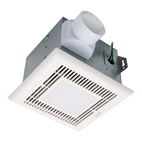
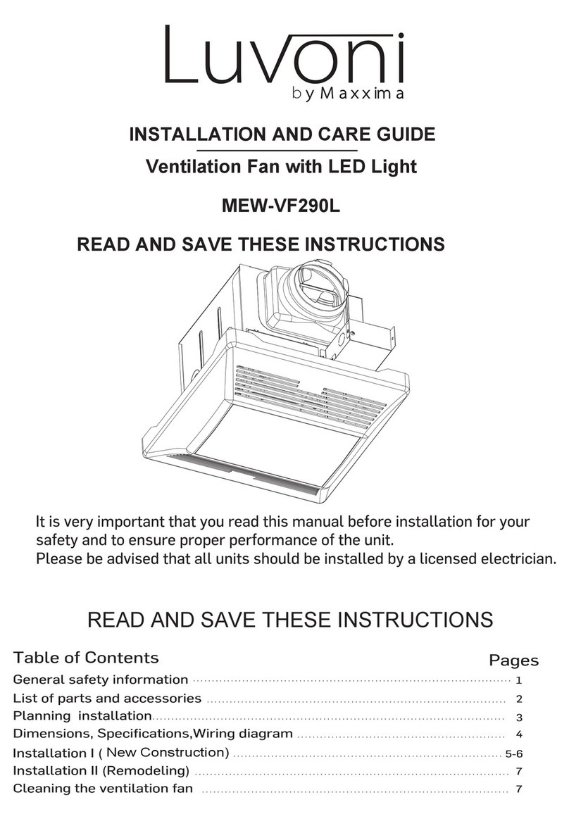
Maxxima Luvoni MEW-VF170 Assembly instructions

Table of contents
General information and parts
.................................................................. 2
Description, sizes and wiring diagram
................................................... 3
Specifications and dimensions ................................................................. 4
General safety information and warnings
............................................. 5
Installation I (new construction)................................................................... 6
Installation II (remodeling)............................................................................ 7
Maintenance and limited warranty
.......................................................... 8
READ AND SAVE THESE INSTRUCTIONS
Please read these instructions carefully before installing, operating or servicing the fan.
Failure to comply with the instructions contained herein could result in personal injury
or property damage. We recommend that you keep this guide for future reference.
1
Ventilation Fan with LED Light
MEW-VF170 & MEW-VF190
READ AND SAVE THESE INSTRUCTIONS
INSTALLATION AND CARE GUIDE

General information
Please read the entire instruction guide prior to installing this fan.
Parts supplied
PART NAME APPEARANCE QUANTITY
Grille1
Long wood screws 8
Short screws 4
Suspension brackets I
2
Suspension brackets II
2
2

3
Description
This product is designed with a built-in thermal cut-off for safety and long life of the motor.
Sizes
Wiring diagram
12 5/8” (32.07 cm)
9
” (23 cm)
12 3/16” (31 cm)
9
” (23 cm)
12 5/8” (32.07 cm)
8 ” (20.3 cm)
4” (10.16 cm)
3/4” (1.9 cm)
Capacitor for long
life of motor
Motor
Black wire
120 V AC 60 Hz
to switch
to neutral
to ground
White wire
Green wire
Junction box
Automatic terminal switch

4
Specifications
Model V HZ DUCT
DIAMETER
NOISE
(SONE)
POWER SPEED
(RPM)
AIR DELIVER AT
0.1” WG (CFM)
MEW-VF170 120 60 4”
(10.16 cm)
0.5 19 W 1000 70 CFM
Dimensions
CEILING
OPENING L
CEILING
OPENING W
CEILING
OPENING D
HOUSING
DIMENSION L
HOUSING
DIMENSION W
HOUSING
DIMENSION D
9.4”
(24 cm)
9.4 ”
(24 cm)
8.23”
(20.9 cm)
9 ”
(23 cm)
9 ”
(23 cm)
7.6”
(19.3 cm)
Note: Be careful to cut the hole exactly because if it is too big, the grille will not hide it.
MEW-VF190 120 60 4”
(10.16 cm)
0.8 24 W 1000 90 CFM

5
General safety information and warnings
1. Electric service supply must be 120 V 60 Hz
2. Follow all local safety and electrical codes as well as Canadian Electrical Code and CSST.
3. This unit must be properly grounded.
4. Always disconnect the power supply prior to servicing the fan, motor or junction box.
5. Do not bend or kink the power wires.
6. Do not install where the room air temperature will exceed 104ºF (40ºC).
7. This ventilation fan is approved for use in a ceiling over a bathtub or shower when installed
on a ground-fault circuit interrupter (GFCI) protected circuit. Do not use fan over a bathtub
or shower that is not approved for that application and marked accordingly.
8. Do not use to exhaust hazardous or explosive vapors.
9. Do not install in a cooking area.
10. Use this unit in the manner intended by the manufacturer.
11. Installation work must be carried out by a qualified person, in accordance to all local
and safety codes, including the rules for fire-rated constructions.
12. Exercise care not to damage existing wiring when cutting or drilling into walls or ceilings.
13. Fans should always be vented to the exterior and in compliance with local codes.
Do not vent exhaust air in spaces within walls, ceiling, attic, crawl space or garage.
14. Do not use this fan with any solid state control device.
15. Prior to service or cleaning, shut off the power supply at the panel and lock to prevent
the power from being turned on. If the panel cannot be locked, clearly mark the panel with
a warning tag to prevent the power from being turned on.
16.Duct work should be installed in a straight line with minimal bends.
18.The switch should not be accessible from inside of bathtub or shower.
19.The fan is to be mounted at least 7 feet (2.1 m) above the floor.
17.Duct work size must be a minimum of the discharge and should not be reduced.
Reducing the duct size can increase fan noise.

6
Installation I (new construction)
1. For ideal ventilation use, hold the body
of the fan with the exhaust side facing
the desired duct direction.
2. Place the body of the fan in between
joists in designated area.
3. If convenient to secure unit to the joist
(otherwise go to step 4), place the unit
against joist and push the fan to the
proper depth and use long screws
(Fig. C).
4. Add the provided brackets (Fig. D)
to the sides that are not connected
to the joists.
5. If the brackets are too short to reach the
joist, use the extensions provided (Fig. E).
6. Attach the duct to the exhaust outlet
of the fan. Secure with duct tape
(Fig. F)
and make sure there is no air leak. Make
sure there are no sharp bends in the duct
line (Fig. G). For 90 degrees angles, use
smooth curves or break into two smaller
angles or curves (Fig. H).
NOTE
For safety and efficiency of the ventilation system,
avoid sharp angles and loose support.
Fig. A
Fig. B
Fig. C
Fig. D
Fig. E
Fig. F
Secure with
duct tape
Fig. G
Wrong
support
Fig. H
Right support
& angle

7
7. Electrical installation:
Wires from the power supply to the unit should not be smaller than size 14 AWG.
The ground wire must be connected to the green wire in junction box, the neutral wire
to the white wire and the hot wire to the black wire.
Installation II (remodeling)
1. In case there is a ventilation unit with the same dimensions in the ceiling,
proceed as follows:
Remove the old unit;
Check the existing duct work and electrical wiring;
Install the unit as described in Installation I.
2. In case you want to make a new opening in existing ceiling:
Find the best location for the ventilation purpose;
Make sure that :
the chosen place has easy access
to exterior air outlet (wall cap or roof
jack) and there will not be a need
for sharp angles or very long duct;
the chosen place for the duct work will
not interfere with any other existing
duct work in the building;
there is no electrical wiring or
any pipes behind the chosen place;
Open the optimal place.
Be careful to
cut the hole exactly. If the hole is too
big, the fan grille will not hide it;
Make the strong support beams for
the unit (make sure it is strong enough
for the weight of the unit);
Provide the duct system and electrical wiring;
Follow the instructions on Installation I.
Ceiling
4 long screws
I-joist
8. Grille installation:
Pinch the mounting springs on the grille and insert them into the narrow
rectangular slots inside the fan. Push grille up towards the ceiling.
Turn power on at the breaker box after installation.
Grille
Mounting
spring

Maintenance
Cleaning the fan
Routine maintenance should be done at least once a year and
should be as follows:
1. Remove cover grille;
2. Wash with lukewarm water and a mild detergent and clean the
grille in a sink and dry with a cloth;
3. Remove dust and dirt from the fan housing with a vacuum cleaner;
4. Dry the body with a cloth or paper towel;
5. Replace the grille.
CAUTION
Never use solvents, thinner or harsh chemical
for cleaning the fan. Do not allow water to enter
the motor. Do not immerse resin parts in water
over 140ºF (60ºC).
Three Year Warranty:
Maxxima extends a 3 year limited warranty to the original purchase that the products
listed are free from defects in material and/or workmanship only. Maxxima will replace
any warrantied product to the original consumer/purchaser if the product fails because of
defects due to workmanship and/or materials within the limited warranty period. Limited
warranty is not transferable and applies to the original installation of the Maxxima product.
This offer does not constitute in any way a product guarantee and Maxxima does not
hereby assume any obligation whatsoever beyond sending a free replacement product.
Vacuum
8
This manual suits for next models
1
Table of contents
Other Maxxima Fan manuals