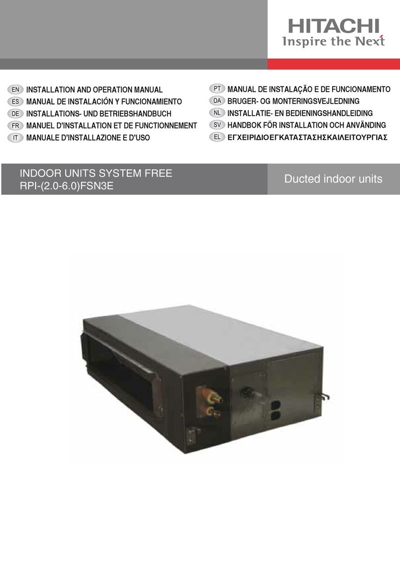
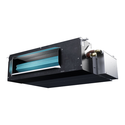
Hitachi RPI-0.4FSN5E User manual

INDOOR UNITS SYSTEM FREE
RPI-(0.4-6.0)FSN5E
INSTALLATION AND OPERATION MANUAL
MANUAL DE INSTALACIÓN Y FUNCIONAMIENTO
INSTALLATIONS- UND BETRIEBSHANDBUCH
MANUEL D’INSTALLATION ET DE FONCTIONNEMENT
MANUALE D’INSTALLAZIONE E D’USO
MANUAL DE INSTALAÇÃO E DE FUNCIONAMENTO
INSTALLATIONS- OG BETJENINGSVEJLEDNING
INSTALLATIE- EN BEDIENINGSHANDLEIDING
INSTALLATION- OCH DRIFTHANDBOK
ΕΓΧΕΙΡΙΔΙΟ ΕΓΚΑΤΑΣΤΑΣΗΣ ΚΑΙ ΛΕΙΤΟΥΡΓΙΑΣ
Ducted indoor units


English
Specications in this manual are subject to change without notice in order that HITACHI may bring the latest innovations
to their customers.
Whilst every effort is made to ensure that all specications are correct, printing errors are beyond HITACHI’s control;
HITACHI cannot be held responsible for these errors.
Español
Las especicaciones de este manual están sujetas a cambios sin previo aviso a n de que HITACHI pueda ofrecer las
últimas innovaciones a sus clientes.
A pesar de que se hacen todos los esfuerzos posibles para asegurarse de que las especicaciones sean correctas, los
errores de impresión están fuera del control de HITACHI, a quien no se hará responsable de ellos.
Deutsch
Bei den technischen Angaben in diesem Handbuch sind Änderungen vorbehalten, damit HITACHI seinen Kunden die
jeweils neuesten Innovationen präsentieren kann.
Sämtliche Anstrengungen wurden unternommen, um sicherzustellen, dass alle technischen Informationen ohne Fehler
veröffentlicht worden sind. Für Druckfehler kann HITACHI jedoch keine Verantwortung übernehmen, da sie außerhalb
ihrer Kontrolle liegen.
Français
Les caractéristiques publiées dans ce manuel peuvent être modiées sans préavis, HITACHI souhaitant pouvoir toujours
offrir à ses clients les dernières innovations.
Bien que tous les efforts sont faits pour assurer l’exactitude des caractéristiques, les erreurs d’impression sont hors du
contrôle de HITACHI qui ne pourrait en être tenu responsable.
Italiano
Le speciche di questo manuale sono soggette a modica senza preavviso afnché HITACHI possa offrire ai propri
clienti le ultime novità.
Sebbene sia stata posta la massima cura nel garantire la correttezza dei dati, HITACHI non è responsabile per eventuali
errori di stampa che esulano dal proprio controllo.
Português
As especicações apresentadas neste manual estão sujeitas a alterações sem aviso prévio, de modo a que a HITACHI
possa oferecer aos seus clientes, da forma mais expedita possível, as inovações mais recentes.
Apesar de serem feitos todos os esforços para assegurar que todas as especicações apresentadas são correctas,
quaisquer erros de impressão estão fora do controlo da HITACHI, que não pode ser responsabilizada por estes erros
eventuais.
Dansk
Specikationerne i denne vejledning kan ændres uden varsel, for at HITACHI kan bringe de nyeste innovationer ud til
kunderne.
På trods af alle anstrengelser for at sikre at alle specikationerne er korrekte, har HITACHI ikke kontrol over trykfejl, og
HITACHI kan ikke holdes ansvarlig herfor.
Nederlands
De specicaties in deze handleiding kunnen worden gewijzigd zonder verdere kennisgeving zodat HITACHI zijn klanten
kan voorzien van de nieuwste innovaties.
Iedere poging wordt ondernomen om te zorgen dat alle specicaties juist zijn. Voorkomende drukfouten kunnen echter
niet door HITACHI worden gecontroleerd, waardoor HITACHI niet aansprakelijk kan worden gesteld voor deze fouten.
Svenska
Specikationerna i den här handboken kan ändras utan föregående meddelande för att HITACHI ska kunna leverera de
senaste innovationerna till kunderna.
Vi på HITACHI gör allt vi kan för att se till att alla specikationer stämmer, men vi har ingen kontroll över tryckfel och kan
därför inte hållas ansvariga för den typen av fel.
Eλλhnika
Οι προδιαγραφές του εγχειριδίου μπορούν να αλλάξουν χωρίς προειδοποίηση, προκειμένου η HITACHI να παρέχει τις
τελευταίες καινοτομίες στους πελάτες της.
Αν και έχει γίνει κάθε προσπάθεια προκειμένου να εξασφαλιστεί ότι οι προδιαγραφές είναι σωστές, η HITACHI δεν
μπορεί να ελέγξει τα τυπογραφικά λάθη και, ως εκ τούτου, δεν φέρει καμία ευθύνη για αυτά τα λάθη.

!ATTENTION
• Thisproductshallnotbemixedwithgeneralhousewasteattheendofitslifeanditshallberetiredaccordingtotheappro-
priatedlocalornationalregulationsinaenvironmentallycorrectway.
• Duetotherefrigerant,oilandothercomponentscontainedinAirConditioner,itsdismantlingmustbedonebyaprofession-
alinstalleraccordingtotheapplicableregulations.Contacttothecorrespondingauthoritiesformoreinformation.
!ATENCIÓN
• Ésteproductonosedebeeliminarconlabasuradomésticaalnaldesuvidaútilysedebedesechardemanerarespetuosaconelmedio
ambientedeacuerdoconlosreglamentoslocalesonacionalesaplicables.
• Debidoalrefrigerante,elaceiteyotroscomponentescontenidosenelsistemadeaireacondicionado,sudesmontajedeberealizarloun
instaladorprofesionaldeacuerdoconlanormativaaplicable.Paraobtenermásinformación,póngaseencontactoconlasautoridades
competentes.
!ACHTUNG
• DassIhrProduktamEndeseinerBetriebsdauernichtindenallgemeinenHausmüllgeworfenwerdendarf,sondernentsprechendden
geltendenörtlichenundnationalenBestimmungenaufumweltfreundlicheWeiseentsorgtwerdenmuss.
• AufgrunddesKältemittels,desÖlsundandererinderKlimaanlageenthaltenerKomponentenmussdieDemontagevoneinemFach-
mannentsprechenddengeltendenVorschriftendurchgeführtwerden.FürweitereInformationensetzenSiesichbittemitdenentsprech-
endenBehördeninVerbindung.
!ADVERTISSEMENT
• Nedoitpasêtremélangéauxorduresménagèresordinairesàlandesavieutileetqu’ildoitêtreéliminéconformémentàlaréglemen-
tationlocaleounationale,dansleplusstrictrespectdel’environnement.
• Enraisondufrigorigène,del’huileetdesautrescomposantsqueleclimatiseurcontient,sondémontagedoitêtreréaliséparuninstalla-
teurprofessionnelconformémentauxréglementationsenvigueur.
!AVVERTENZE
• IndicazioniperilcorrettosmaltimentodelprodottoaisensidellaDirettivaEuropea2002/96/ECeDlgs25luglio2005n.151
• Ilsimbolodelcassonettobarratoriportatosull’apparecchiaturaindicacheilprodottoallanedellapropriavitautiledeveessereraccolto
separatamentedaglialtririuti.
• L’utentedovrà,pertanto,conferirel’apparecchiaturagiuntaanevitaagliidoneicentridiraccoltadifferenziatadeiriutielettronicied
elettrotecnici,oppurericonsegnarlaalrivenditorealmomentodell’acquistodiunanuovaapparecchiaturaditipoequivalente.
• L’adeguataraccoltadifferenziatadelleapparecchiaturedismesse,perilloroavvioalriciclaggio,altrattamentoedallosmaltimentoam-
bientalmentecompatibile,contribuisceadevitarepossibilieffettinegativisull’ambienteesullasaluteefavorisceilriciclodeimaterialidi
cuiècompostal’apparecchiatura.
• Nontentatedismontareilsistemaol’unitàdasolipoichèciòpotrebbecausareeffettidannosisullavostrasaluteosull’ambiente.
• Vogliatecontattarel’installatore,ilrivenditore,oleautoritàlocaliperulterioriinformazioni.
• Losmaltimentoabusivodelprodottodapartedell’utentepuòcomportarel’applicazionedellesanzioniamministrativedicuiall’articolo50
eseguentidelD.Lgs.n.22/1997.
!CUIDADO
• Oseuprodutonãodevesermisturadocomosdesperdíciosdomésticosdecaráctergeralnonaldasuaduraçãoequedeveserelimi-
nadodeacordocomosregulamentoslocaisounacionaisadequadosdeumaformacorrectaparaomeioambiente.
• Devidoaorefrigerante,aoóleoeaoutroscomponentescontidosnoArcondicionado,adesmontagemdeveserrealizadaporuminsta-
ladorprossionaldeacordocomosregulamentosaplicáveis.Contacteasautoridadescorrespondentesparaobtermaisinformações.
!ADVASEL!
• Atproduktetikkemåsmidesudsammenmedalmindeligthusholdningsaffald,menskalbortskaffesioverensstemmelsemeddegæl-
dendelokaleellernationalereglerpåenmiljømæssigkorrektmåde.
• Daklimaanlæggetindeholderkølemiddel,oliesamtandrekomponenter,skalafmonteringforetagesafenfagmandioverensstemmelse
meddegældendebestemmelser.Kontaktdepågældendemyndighederforatfåyderligereoplysninger.
!VOORZICHTIG
• Dithoudtindatuwproductnietwordtgemengdmetgewoonhuisvuilwanneeruhetwegdoetendathetwordtgescheidenopeenmilieu-
vriendelijkemaniervolgensdegeldigeplaatselijkeenlandelijkereguleringen.
• Vanwegehetkoelmiddel,deolieenandereonderdelenindeairconditionermoethetapparaatvolgensdegeldigereguleringdooreen
professioneleinstallateuruitelkaargehaaldworden.Neemcontactopmetdebetreffendeoverheidsdienstvoormeerinformatie.
!FÖRSIKTIGHET
• Detinnebärattprodukteninteskaslängastillsammansmedvanligthushållsavfallutankasseraspåettmiljövänligtsättienlighetmed
gällandelokalellernationelllagstiftning.
• Luftkonditioneringsaggregatetinnehållerkylmedium,oljaochandrakomponenter,vilketgörattdetmåstedemonterasavenfackmani
enlighetmedtillämpligaregelverk.Takontaktmedansvarigmyndighetomduvillhamerinformation.
!ΠΡΟΣΟΧΗ
• Σημαίνειότιτοπροϊόνδενθαπρέπεινααναμιχθείμεταδιάφοραοικιακάαπορρίμματαστοτέλοςτουκύκλουζωήςτουκαιθαπρέπεινα
αποσυρθείσύμφωναμετουςκατάλληλουςτοπικούςήεθνικούςκανονισμούςκαιμετρόποφιλικόπροςτοπεριβάλλον.
• Λόγωτουψυκτικού,τουλαδιούκαιάλλωνστοιχείωνπουπεριέχονταιστοκλιματιστικό,ηαποσυναρμολόγησήτουπρέπειναγίνειαπό
επαγγελματία τεχνικό και σύμφωνα με τους ισχύοντες κανονισμούς. Για περισσότερες λεπτομέρειες, επικοινωνήστε με τις αντίστοιχες
αρχές.

EN English Original Version
ES Español Versión traducida
DE Deutsch Übersetzte Version
FR Français Version traduite
IT Italiano Versione tradotta
PT Português Versão traduzidal
DA Dansk Oversat version
NL Nederlands Vertaalde versie
SV Svenska Översatt version
EL Ελληνικα Μεταφρασμένη έκδοση
INDEX
1 GENERAL INFORMATION
2 NAME OF PARTS
3 UNITS INSTALLATION
4 REFRIGERANT PIPING CONNECTION
5 DRAIN PIPING
6 ELECTRICAL WIRING
ÍNDICE
1 INFORMACIÓN GENERAL
2 COMPONENTES
3 INSTALACIÓN DE LAS UNIDADES
4 CONEXIÓN DE LAS TUBERÍAS DE REFRIGERANTE
5 TUBERÍA DE DESAGÜE
6 CABLEADO ELÉCTRICO
INHALTSVERZEICHNIS
1 ALLGEMEINE INFORMATIONEN
2 TEILEBEZEICHNUNG
3 GERÄTEINSTALLATION
4 KÄLTEMITTELLEITUNGS-ANSCHLUSS
5 ABFLUSSLEITUNGEN
6 KABELANSCHLUSS
INDEX
1 INFORMATIONS GÉNÉRALES
2 NOMENCLATURE DES PIÈCES
3 INSTALLATION DES UNITÉS
4 CONNEXION DES TUYAUTERIES FRIGORIFIQUES
5 TUYAU D'ÉVACUATION
6 CÂBLAGE ÉLECTRIQUE
INDICE
1 INFORMAZIONI GENERALI
2 NOME DEI COMPONENTI
3 INSTALLAZIONE DELLE UNITÀ
4 COLLEGAMENTO DELLA LINEA REFRIGERANTE
5 LINEA DI DRENAGGIO
6 COLLEGAMENTI ELETTRICI
ÍNDICE
1 INFORMAÇÃO GERAL
2 NOME DAS PEÇAS
3 INSTALAÇÃO DAS UNIDADES
4 LIGAÇÃO DOS TUBOS DE REFRIGERANTE
5 TUBAGEM DE DESCARGA
6 LIGAÇÕES ELÉTRICAS
INDHOLDSFORTEGNELSE
1 GENEREL INFORMATION
2 NAVN PÅ DELE
3 INSTALLATION AF ENHEDER
4 TILSLUTNING AF KØLERØR
5 AFLØBSRØR
6 ELEKTRISK LEDNINGSFØRING
INHOUDSOPGAVE
1 ALGEMENE INFORMATIE
2 NAMEN VAN ONDERDELEN
3 DE UNITS INSTALLEREN
4 DE KOELMIDDELLEIDINGEN AANSLUITEN
5 AFVOERLEIDING
6 ELEKTRISCHE BEDRADING
INNEHÅLLSFÖRTECKNING
1 ALLMÄN INFORMATION
2 DELARNAS NAMN
3 INSTALLATION AV ENHETER
4 ANSLUTNING FÖR KYLRÖR
5 DRÄNERINGSRÖR
6 ELEKTRISK ANSLUTNING
ΕΥΡΕΤΗΡΙΟ
1 ΓΕΝΙΚΕΣ ΠΛΗΡΟΦΟΡΙΕΣ
2 ΟΝΟΜΑΤΑ ΕΞΑΡΤΗΜΑΤΩΝ
3 ΕΓΚΑΤΑΣΤΑΣΗ ΜΟΝΑΔΩΝ
4 ΣΥΝΔΕΣΗ ΣΩΛΗΝΩΣΗΣ ΨΥΚΤΙΚΟΥ
5 ΣΩΛΗΝΩΣΕΙΣ ΑΠΟΧΕΤΕΥΣΗΣ
6 ΗΛΕΚΤΡΙΚΗ ΚΑΛΩΔΙΩΣΗ


ENGLISH
GENERAL INFORMATION
PMML0385 rev.0 - 07/20171
1 GENERAL INFORMATION
1.1 GENERAL NOTES
No part of this publication may be reproduced, copied, led
or transmitted in any shape or form without the permission of
Johnson Controls-Hitachi Air Conditioning Spain, S.A.U.
Within the policy of continuous improvement of its products,
Johnson Controls-Hitachi Air Conditioning Spain, S.A.U.
reserves the right to make changes at any time without prior
notication and without being compelled to introducing them into
products subsequently sold. This document may therefore have
been subject to amendments during the life of the product.
HITACHI makes every effort to offer correct, up-to-date
documentation. Despite this, printing errors cannot be controlled
by HITACHI and are not its responsibility.
As a result, some of the images or data used to illustrate this
document may not refer to specic models. No claims will be
accepted based on the data, illustrations and descriptions
included in this manual.
No type of modication must be made to the equipment without
prior, written authorisation from the manufacturer.
1.2 PRODUCT GUIDE
1.2.1 Prior check
?NOTE
Check, depending on the name of the model, the type of air conditioning
system tted, the abbreviated code and reference in this instruction
manual. This Installation and Operating Manual only refers to
RPI-(0.4-6.0)FSN5E units.
Check, in accordance with the Installation and Operating
Manuals included with the outdoor and indoor units, that all the
information necessary for the correct installation of the system is
included. If this is not the case, please contact your distributor.
1.2.2 Classication of indoor unit models
Unit type (indoor unit): RPI
Position-separating hyphen (xed)
Capacity (HP): (0.4-6.0)
FS: SYSTEM FREE
N: R410A refrigerant
5: Series
E : Made in Europe
XXX – XX FS N 5 E
1.3 SAFETY
1.3.1 Symbols used
During normal air conditioning system design work or unit
installation, greater attention must be paid in certain situations
requiring particular care in order to avoid injuries and damage to
the unit, the installation or the building or property.
Situations that jeopardise the safety of those in the surrounding
area or that put the unit itself at risk will be clearly indicated in
this manual.
To indicate these situations, a series of special symbols will be
used to clearly identify these situations.
Pay close attention to these symbols and to the messages
following them, as your safety and that of others depends on it.
!DANGER
• The text following this symbol contains information and
instructionsrelatingdirectlytoyoursafetyandphysicalwellbeing.
• Nottakingtheseinstructionsintoaccountcouldleadtoserious,
very serious or even fatal injuries to you and others in the
proximitiesoftheunit.
In the texts following the danger symbol you can also nd
information on safe procedures during unit installation.
!CAUTION
• The text following this symbol contains information and
instructions relating directly to your safety and physical
wellbeing.
• Nottakingtheseinstructionsintoaccountcouldleadtominor
injuriestoyouandothersintheproximitiesoftheunit.
• Not taking these instructions into account could lead to unit
damage.
In the texts following the caution symbol you can also nd
information on safe procedures during unit installation.
?NOTE
• The text following this symbol contains information or instructions that
may be of use or that require a more thorough explanation.
• Instructions regarding inspections to be made on unit parts or systems
may also be included.

GENERAL INFORMATION
PMML0385 rev.0 - 07/2017
2
1.3.2 Additional information about safety
!DANGER
• HITACHIisnotabletoforeseeallthecircumstanceswhichmay
resultinapotentialdanger.
• Donotpourwaterintheindoororoutdoorunit.Theseproducts
arettedwithelectriccomponents.Ifwatercomesintocontact
with electric components, this will cause a serious electric
shock.
• Donothandleoradjustthesafetydevicesinsidetheindoorand
outdoorunits.Thehandlingoradjustmentofthesedevicesmay
resultinseriousaccident.
• Donotopentheservicecoveroraccesspaneloftheindoorand
outdoorunitswithoutdisconnectingthemainsupply.
• In the event of re, switch off the mains, put out the re
immediatelyandcontactyourservicesupplier.
• Checkthattheearthcableiscorrectlyconnected.
• Connecttheunittoacircuitbreakerofthespeciedcapacity.
!CAUTION
• Refrigerant leaks may hinder respiration as the gas displaces the air
in the room.
• Fit the indoor unit, the outdoor unit, the remote control and the cable
at a minimum of 3 metres away from sources of strong radiation from
electromagnetic waves, such as medical equipment.
• Do not use sprays, such as insecticides, varnishes or enamels or any
other inammable gas within a metre of the system.
• If the circuit breaker or supply fuse of the unit comes on frequently,
stop the system and contact the service suppler.
• Do not carry out maintenance or inspection work yourself. This work
must be carried out by qualied service personnel with suitable tools
and resources for the work.
• Do not place any foreign material (branches, sticks, etc.) in the air
inlet or outlet of the unit. These units are tted with high speed fans
and contact with any object is dangerous.
• This appliance must be used only by adult and capable people,
having received the technical information or instructions to handle this
appliance properly and safely.
• Children should be supervised to ensure that they do not play with
the appliance.
?NOTE
• The air in the room should be renewed and the room ventilated every
3 or 4 hours.
• The system tter and specialist shall provide anti-leak safety in
accordance with local regulations.
1.4 PURPOSE OF THIS MANUAL
This air conditioner has been designed for standard air
conditioning for human beings. For use in other applications,
please contact your HITACHI dealer or service contractor
The air conditioning system should only be installed by qualied
personnel, with the necessary resources, tools and equipment,
who are familiar with the safety procedures required to
successfully carry out the installation.
The supplementary information about the purchased products
is supplied in a CD-ROM, which can be found bundled with the
outdoor unit. In case that the CD-ROM is missing or it is not
readable, please contact your HITACHI dealer or distributor.
PLEASE READ THE MANUAL AND THE FILES ON THE
CD-ROM CAREFULLY BEFORE STARTING WORK ON THE
INSTALLATION OF THE AIR CONDITIONING SYSTEM.
Failure to observe the instructions for installation, use and
operation described in this documentation may result in
operating failure including potentially serious faults, or even the
destruction of the air conditioning system.
It is assumed that the air conditioning system will be installed
and maintained by responsible personnel trained for the
purpose. If this is not the case, the customer should include all
the safety, caution and operating signs in the native language of
the personnel responsible.
Do not install the unit in the following places, as this may lead to
a re, deformities, rusting or faults:
• Places where oil is present (including oil for machinery).
• Places with a high concentration of sulphurous gas, such as
spas.
• Places where ammable gases may be generated or
circulate.
• Places with a saline, acidic or alkaline atmosphere.
Do not install the unit in places where silicon gas is present. Any
silicon gas deposited on the surface of the heat exchanger will
repel water. As a result, the condensate water will splash out
of the collection tray and into the electrical box. Water leaks or
electrical faults may eventually be caused.
Do not install the unit in a place where the current of expelled
air directly affects animals or plants as they could be adversely
affected.
ENGLISH
NAME OF PARTS
PMML0385 rev.0 - 07/2017
3
2 NAME OF PARTS
RPI-0.4FSN5E
No. Part name
1 Fan casing
2 Fan
3 Fan motor
4Heat exchanger
5 Header
6Expansion valve
7Air lter
8 Refrigerant gas pipe connection
9 Refrigerant liquid pipe connection
10 Electrical control box
11 Air inlet
12 Air outlet
13 Drain pump
14 Drain pipe connection
15 Filter xing tabs (upper side)
16 Filter xing tabs (lower side)

NAME OF PARTS
PMML0385 rev.0 - 07/2017
4
RPI-(0.6-1.5)FSN5E
No. Part name
1 Fan casing
2 Fan
3 Fan motor
4Heat exchanger
5 Header
6Expansion valve
7Air lter
8 Refrigerant gas pipe connection
9 Refrigerant liquid pipe connection
10 Electrical control box
11 Air inlet
12 Air outlet
13 Drain pump
14 Drain pipe connection
15 Filter xing tabs (upper side)
16 Filter xing tabs (lower side)

ENGLISH
NAME OF PARTS
PMML0385 rev.0 - 07/2017
5
RPI-(2.0-3.0)FSN5E
No. Part name
1 Fan casing
2 Fan
3 Fan motor
4Heat exchanger
5 Header
6Expansion valve
7Air lter
8 Refrigerant gas pipe connection
9 Refrigerant liquid pipe connection
10 Electrical control box
11 Air inlet
12 Air outlet
13 Drain pump
14 Drain pipe connection
15 Filter xing tabs (upper side)
16 Filter xing tabs (lower side)

NAME OF PARTS
PMML0385 rev.0 - 07/2017
6
RPI-(4.0-6.0)FSN5E
No. Part name
1 Fan casing
2 Fan
3 Fan motor
4Heat exchanger
5 Header
6Expansion valve
7Air lter
8 Refrigerant gas pipe connection
9 Refrigerant liquid pipe connection
10 Electrical control box
11 Air inlet
12 Air outlet
13 Drain pump
14 Drain pipe connection
15 Filter xing tabs (upper side)
16 Filter xing tabs (lower side)

ENGLISH
UNITS INSTALLATION
PMML0385 rev.0 - 07/2017
7
3 UNITS INSTALLATION
!DANGER
• Checktoensurethattheaccessoriesarepackedwiththeindoor
unit.
• Donotinstalltheindoorunitsoutdoors.Ifinstalledoutdoors,an
electrichazardorelectricleakagewilloccur.
• Considertheairdistributionfromeachindoorunittothespace
ofthe room,andselect asuitablelocation so thatuniform air
temperatureintheroomcanbeobtained.Itisrecommendedthat
theindoorunitsbeinstalled2.3to3metersfromtheoorlevel.If
theunitisinstalledhigherthan3meters,itisalsorecommended
that a fan be utilised to obtain uniform air temperature in the
room.
• Avoid obstacles which may hamper the air intake or the air
dischargeow.
• Payattentiontothefollowingpointswhentheindoorunitsare
installedinahospitalorotherplaceswherethereareelectronic
wavesfrommedicalequipment,etc.
• Do not install the indoor units where electromagnetic wave is
directly radiated to the electrical box, remote control cable or
remotecontrolswitch.
• Installtheindoorunitsandcomponentsasfaraspracticalorat
least3metersfromtheelectromagneticwaveradiator.
• Prepareasteelboxandinstalltheremotecontrolswitchin it.
Prepareasteelconduittubeandwiretheremotecontrolcablein
it.Thenconnectthegroundwirewiththeboxandtube.
• Installanoiselterwhenthepowersupplyemitsharmfulnoises.
• Thisunitisexclusivenonelectricalheatertypeindoorunit.Itis
prohibitedtoinstallaelectricalheaterintheeld.
• Mount suspension bolts using M10 (W3/8) as size, as shown
below:
• Donotputanyforeignmaterialintotheindoorunitandcheckto
ensurethatnoneexistintheindoorunitbeforetheinstallation
andtestrunning.Otherwiseareorfailure,etc.,mayoccur.
!CAUTION
• Do not install the indoor units in a ammable environment to avoid a
re or an explosion.
• Check to ensure that the ceiling slab is strong enough. If not strong
enough, the indoor unit may fall down on you.
• Do not install the indoor units, outdoor unit, remote control switch and
cable within approximately 3 meters of strong electromagnetic wave
radiators such as medical equipment.
• Do not install the indoor units in a machinery shop or kitchen where
vapor from oil or mist ows to the indoor units. The oil will deposit on
the heat exchanger, thereby reducing the indoor unit performance,
and may deform. In the worst case, the oil damages the plastic parts
of the indoor unit.
• To avoid any corrosive action to the heat exchangers, do not install
the indoor units in an acid or alkaline environment.
• When lifting or moving the indoor unit, use appropriate slings to avoid
damage and be careful not to damage the insulation material on units
surface.
I-Beam
Suspension Bolts
(W3/8 or M10)
For Concrete
Slab 150~160mm
Sling Bolt
(W3/8 or M10)
Square
washers
Wooden Bar
(60 mm to 90 mm Square)
Steel
Concrete Nuts
Anchor Bolt
Wooden Beam
3.1 UNIT INSTALLATION
3.1.1 Installation
Install the indoor unit with a proper clearance around it paying careful attention of installation direction for the piping, wiring and
maintenance working space, as shown below.
Service Space
RPI-0.4FSN5E RPI-(0.6-1.5)FSN5E
(mm)

UNITS INSTALLATION
PMML0385 rev.0 - 07/2017
8
RPI-(2.0-3.0)FSN5E
RPI-(4.0-6.0)FSN5E
Mounting the suspension bolts
-Using the dimension shown above select the nal
location and installation direction of the Indoor Unit
paying careful attention to the space for the piping, wiring
and maintenance.
-Install the sling bolts, M10 or greater are also
recommended, and suspend the indoor unit using the
following steps:
1 Hook suspension bracket to the nut and washer of each sling
bolt, as shown, starting from one side.
2 After check the nut and washer are correctly xes by the
retainers of the suspension bracket, hook the suspension
bracket of the other side to nut and washer.
Left side
Suspension
bolt
Suspension
bracket
Inlet air
Washer
Nut
Right side
Washer
Nut
Drain pan level
FRONT VIEW
Condensate drain connection
-Make sure that the foundation is at, taking into account
the maximum foundation gradient.
-The unit should be installed so that one side of the unit
is slightly (approximately 5 mm) lower than the other
side, in order to avoid the incorrect position of the drain
discharge.
Tighten the nuts of the suspension bolts with the suspension
brackets after adjustment is completed. Special plastic paint
must be applied to the bolts and nuts in order to prevent them
from loosening.
?NOTE
Keep the unit as well as relevant equipment covered with the vinyl cover
during installation work.

ENGLISH
UNITS INSTALLATION
PMML0385 rev.0 - 07/2017
9
3.1.2 Connecting eld supply duct and suction air lter servicing
Field Supply Duct installation
Fix the Flexible Air Duct to External Faces of unit anges (the unit is equipped with factory supply anges for this purpose).
It is recommended to use a Flexible eld supply Duct portion in order to avoid any abnormal sound vibration.
RPI units are supplied with standard Air Filter at the suction side. This lter is provided for the cases in which no Suction Duct is
applied (or it is very short).
Standard air lter
(factory-supplied)
Air lter (factory-supplied or
adapted factory one)
Fig. 1
Fig. 2
It is recommended the following indications depending on the installation.
-Keep the standard Air Filter in case of no Suction Duct is applied (g.1)
-In case of applying Suction Duct, it is recommended to apply Air Filter at the inlet point of Suction Duct, removing the
standard Air Filter of the unit (g. 2)
Suction air lter servicing
Do not remove this
screw
1 Remove the stay support (4 screws) from the unit.
2 Remove the cover.
3 The lter is held by a tab (2x) in the cover. The lter must be gently pushed in order to make it come off from the tab.
4 To put the lter back in place, pass the lter through the lateral guides and t it in the upper tabs. Then push the lter in order to
insert it in the bottom tabs.

UNITS INSTALLATION
PMML0385 rev.0 - 07/2017
10
Air inlet direction change
Inlet air
direction
Inlet cover
Bottom cover
Optional inlet air direction
Change inlet
cover side
For RPI-(2.0-6.0)FSN5E units, Air inlet direction could be modied by changing inlet cover direction as shown in the diagram.
For RPI-(0.4-1.5)FSN5E units the air inlet direction can be modied by adding and optional accessory specically designed for this
purpose.
3.1.3 Fan performance curve
These units provide three options for the installation: High static pressure, standard static pressure or Low static pressure conditions
in each particular installation, as shown below Fan Performance Curve.
RPI-0.4FSN5E RPI-0.6FSN5E
External static pressure (Pa)
Air ow (m3/min) Air ow (m3/min)

ENGLISH
UNITS INSTALLATION
PMML0385 rev.0 - 07/2017
11
RPI-(0.8-1.0)FSN5E RPI-1.5FSN5E
External static pressure (Pa)
Air ow (m3/min) Air ow (m3/min)
RPI-2.0FSN5E RPI-2.5FSN5E
External static pressure (Pa)
Air ow (m3/min) Air ow (m3/min)
RPI-3.0FSN5E RPI-4.0FSN5E
External static pressure (Pa)
Air ow (m3/min) Air ow (m3/min)
RPI-5.0FSN5E RPI-6.0FSN5E
External static pressure (Pa)
Air ow (m3/min) Air ow (m3/min)

REFRIGERANT PIPING CONNECTION
PMML0385 rev.0 - 07/2017
12
Fan speed availability according to the selected external static pressure
According to the selected of External Static Pressure conguration (through the optional function C5) the fan speed available in the
Remote Control Switch are the ones show as example in the following pictures.
External Static Pressure (Pa)
High static pressure (SP-01)
External Static Pressure (Pa)
Standard static pressure (SP-00)
External Static Pressure (Pa)
Low static pressure (SP-02)
Air ow (m³/min) Air ow (m³/min) Air ow (m³/min)
?NOTE
"High H" speed available only with PC-ARFPE remote control switch.
3.1.4 Static pressure setting
RPI units have been provided by three Static Pressure levels regulation depending on the installation requirements.
High Static Pressure, Standard Static Pressure (Factory setting) and Low Static Pressure conditions are available.
Static Pressure setting shall be made from the Remote Control Switch. For changing to High and Low Static Pressure level, refer to
Installation and Operation Manual remote control.
4 REFRIGERANT PIPING CONNECTION
Position of piping connection is the following: mm (±2)
RPI-(0.4-1.5)FSN5E
Liquid piping connection
Gas piping connection
Drain pipe
connection
RPI-(2.0-6.0)FSN5E
Liquid piping connection
Gas piping connection
2.0 - 3.0 HP 4.0 - 6.0 HP
a192 198
b167 173
c132 138
Drain pipe
connection
4.1 SIZE OF PIPING CONNECTION
Piping size
mm (in)
Model RPI 0.4-1.5 2.0 2.5/3.0 4.0-6.0
Gas piping Ø 12.7
(1/2”)
Ø 15.88
(5/8”)
Ø 15.88
(5/8”)
Ø 15.88
(5/8”)
mm (in)
Model RPI 0.4-1.5 2.0 2.5/3.0 4.0-6.0
Liquid
piping
Ø 6.35
(1/4”)
Ø 6.35
(1/4”)
Ø 9.52
(3/8”)
Ø 9.52
(3/8”)

ENGLISH
DRAIN PIPING
PMML0385 rev.0 - 07/2017
13
5 DRAIN PIPING
5.1 GENERAL
?NOTE
Install drainage in accordance with national and local codes.
!CAUTION
• Do not create an upper-slope or rise for the drain piping, since drain
water will ow back to the unit and leakage to the room will occur
when the unit operation is stopped.
• Do not connect the drain pipe with sanitary or sewage piping or any
other drainage piping.
• When the common drain piping is connected with other indoor units,
the connected position of each indoor unit must be higher than the
common piping. The pipe size of the common drain pipe must be
large enough according to the unit size and number of unit.
Common drain piping
1/25~1/100 Down Slope
• Drain piping will require insulating if the drain is installed in a location
where condensation forming on the outside of drain pipe may drop
and cause damage. The insulation for the drain pipe must be selected
to insure vapor sealing and prevent condensation forming.
• Drain trap should be installed next to indoor unit. This trap must be
designed to good practice and be checked with water (charged)
and tested for correct ow. Do not tie or clamp the drain pipe and
refrigerant pipe together.
After performing drain piping work and electrical wiring, check to
ensure that water ows smoothly as in the following procedure:
Checking with drain-up mechanism and oat
switch
-Switch ON the power supply.
-Pour approximately 1.8 liters of water into the drain pan.
Then oat switch stops the system automatically. In this
operations the drain pump do not stops.
-Check to ensure that the water ows smoothly or whether
no water leakage occurs. When water cannot be found
at the end of the drain piping, pour another approximately
1.8 liters of water into the drain pan.
-Switch OFF the power supply after.
?NOTE
Pay attention to the thickness of the insulation when the left side piping is
performed. If it is too thick, piping can not be installed in the unit.
5.2 DRAIN PIPE CONNECTION
1 Prepare a polyvinyl chloride pipe with a 32 mm outer
diameter.
2 Fasten the tubing to the drain hose with an adhesive and
the clamp. The drain piping must be performed with a down-
slope pitch of 1/25 to 1/100.
Gradient of Drain piping
Max.
850 mm
1/25~1/100
down slope
3 Insulate the drain pipe after connecting the drain hose.
Insulation (eld-supplied)
Side Unit
1/25~1/100
down slope
Polyvinyl chloride tube
(eld-supplied)
Clamp Drain
piping

ELECTRICAL WIRING
PMML0385 rev.0 - 07/2017
14
6 ELECTRICAL WIRING
6.1 ELECTRICAL WIRING CONNECTION FOR INDOOR UNIT
6.1.1 Electrical box location
The service panel for the fan motor of the indoor unit is provided at the bottom side of the unit, and the service panel for the
electrical box is provided at the right side of the unit as shown below.
RPI-(0.4-1.5)FSN5E
Wiring
connection
Liquid pipe
Gas pipe Drain hose
Electrical
box
RPI-(2.0-6.0)FSN5E
Wiring
connection
Liquid pipe
Gas pipe Drain hose
Electrical
box
6.1.2 Electrical wiring installation
1 Open the bottom side Service Panel
2 Cut out the centre of the rubber bushing in the wiring
connection hole of the unit showed above and of the
electrical box shown below.
3 Connect the power supply and ground wires to the terminals
in the electrical box as shown below.
4 Connect the wires between the indoor unit and the outdoor
unit to the terminals 1 and 2 in the electrical box.
5 Connect the cable of the Remote Control Switch to the
terminals A and B in electrical box.
6 Tightly x the wires with the cord clamp inside the indoor
units.
7 Seal the wiring connection hole after running the cables
with the seal material (cover plate) to protect the unit from
condensed water and insects.
!CAUTION
Use twisted shielded pair cable or shield pair cable for transmission wires
between the indoor and the outdoor units, and connect the shielded part
to the earth screw in the electrical box of the indoor unit as shown in the
gure.
6.1.3 Electrical box layout
RPI-(0.4-1.5)FSN5E
PCB
TB
This manual suits for next models
7
Table of contents
Languages:
Other Hitachi Fan manuals

Hitachi
Hitachi UF 18DSL User manual

Hitachi
Hitachi P-AP56NAM User manual

Hitachi
Hitachi RPIM-0.8FSN2E User manual

Hitachi
Hitachi ESP-T2000R User manual

Hitachi
Hitachi airCore 700 Instruction Manual

Hitachi
Hitachi RPI-1.5FSRE User manual

Hitachi
Hitachi HEF-110M User manual

Hitachi
Hitachi E-52XN2 User manual

Hitachi
Hitachi KPI User manual

Hitachi
Hitachi RCIM-0.4FSRE User manual