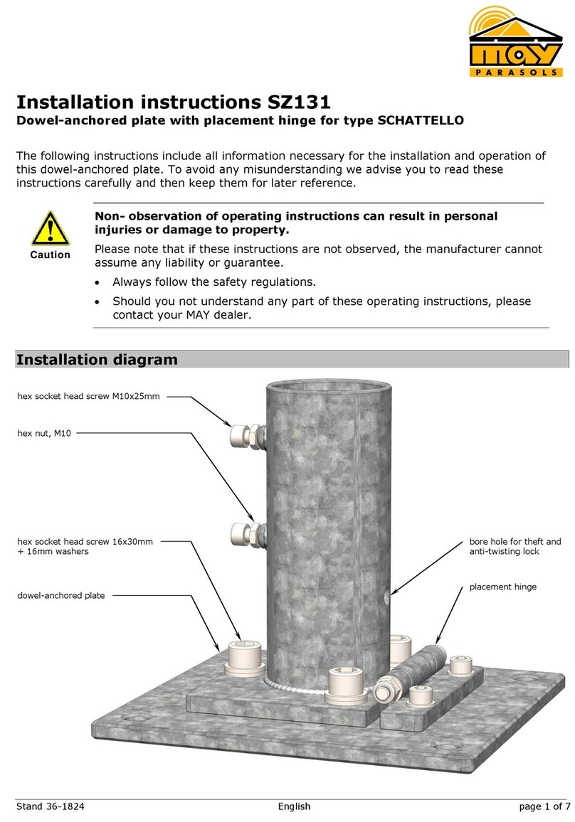
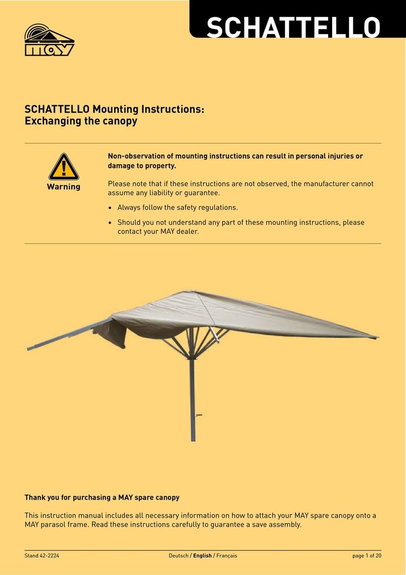
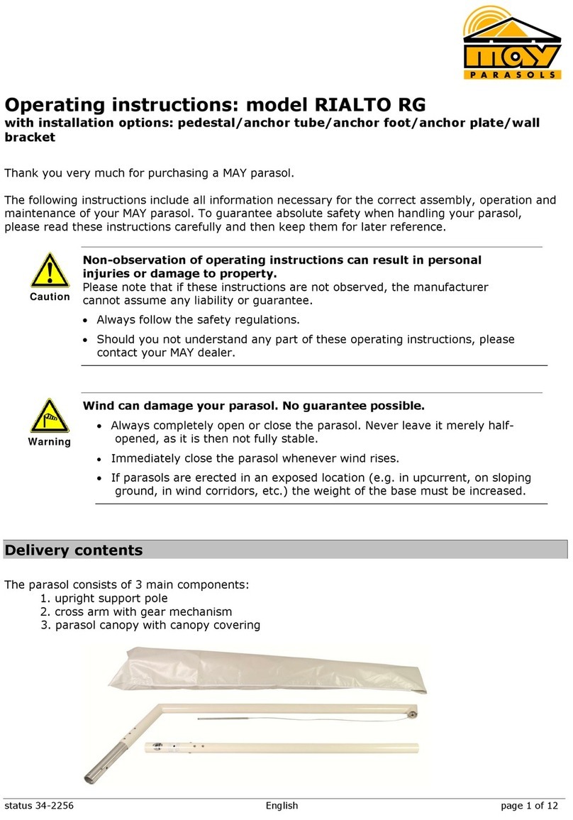
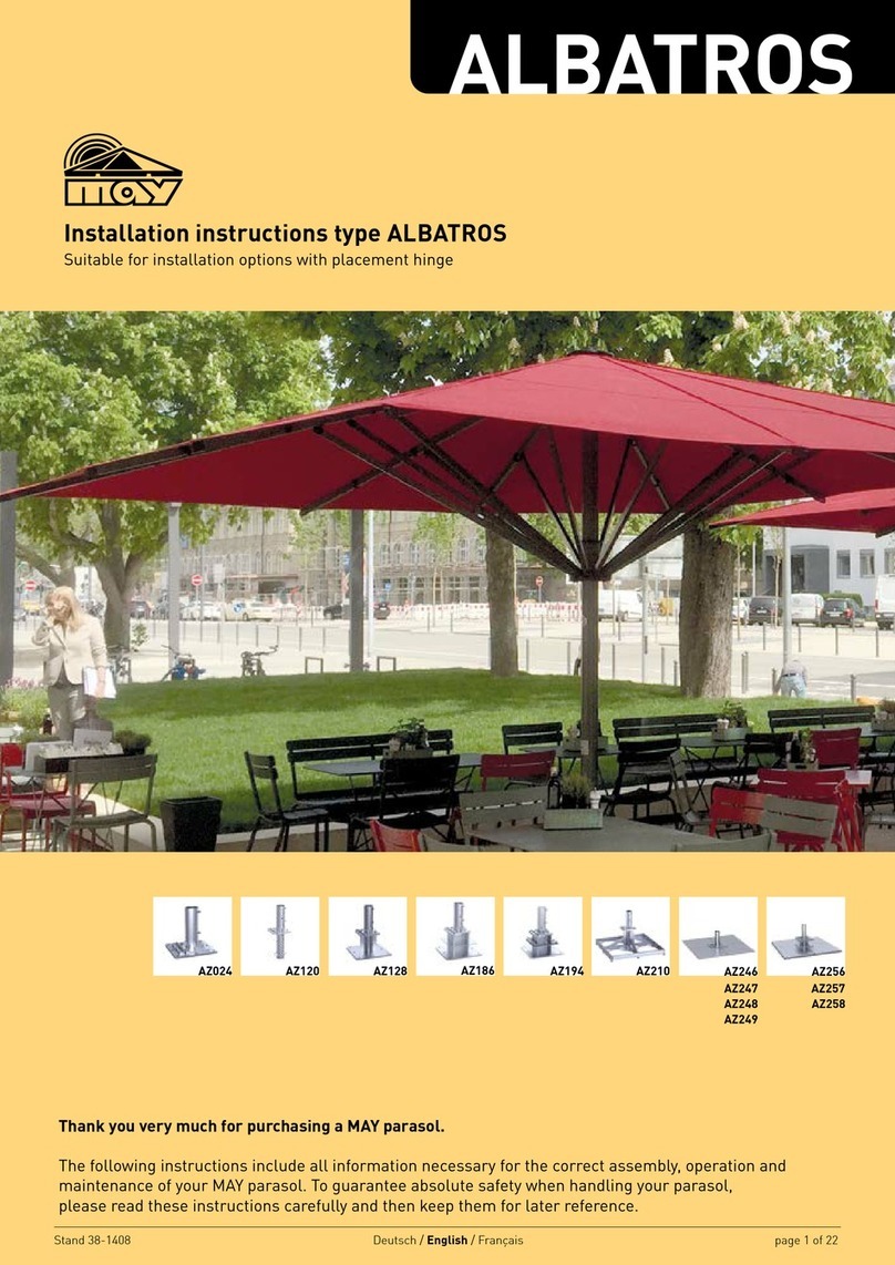
MAY PARASOLS AZ256 User manual

Stand 40-0414 English page 1 of 13
Installation instruction AZ256, AZ257, AZ258 and AZ259
Customized base plate, free-standing, with placement hinge and upper anchor tube AZ120 for
ALBATROS Parasols. Please refer to the MAY brochure „commercial parasols“ for the weights
required per model. Go to “ALBATROS – Sizes and Technical Data” and look up the “Minimum-
ballast”. In case of non-compliance, the MAY company cannot assume any liability.
The following instructions include all information necessary for the assembly of this base pedestal.
To avoid any misunderstanding, we advise you to read these instructions carefully and then keep
them for later reference.
Non- observation of mounting instructions can result in personal
injuries or damage to property.
Please note that if these instructions are not observed, the manufacturer cannot
assume any liability or guarantee.
Always follow the safety regulations.
Should you not understand any part of these mounting instructions, please
contact your MAY dealer.
Diagram showing mounting procedure
Caution
bore hole for theft and
anti-twisting lock
placement hinge
base plate, 4x
not visible after
installation
upper tube
visible after installation
bottom component/
base
flange plate

Stand 40-0414 English page 2 of 13
wooden planking
reinforced concrete
base

Stand 40-0414 English page 3 of 13
Functioning of the placement hinge
The placement hinge will not function if the total height is not correctly
dimensioned.
If item AZ256 / AZ257 / AZ258 / AZ259 has, by mistake, been ordered and
installed with the wrong height measurements, do at least make sure that the
bottom component is not set too far down in the ground. If there is a difference
of more than 50 mm between the top of the lower anchor tube and the floor
surface, the placement hinge cannot be tilted and the parasol cannot be erected.
Moreover, the electrician will not be able to run the power cables.
Be sure to measure and specify the correct total height for installation.
Caution
wrong height
measurement: too
short for installation
height
measurement
necessary for
correct
installation
lower edge of
steel anchor
plate

Stand 40-0414 English page 4 of 13
Screwing the base pedestal together
1. Centre the 4 base plates around the spot determined for the main axis of your ALBATROS
giant parasol. Each of the corners with three threads must point to the main axis. The
bottom layer of the steel plates must have 3 threads.
2. Determine the correct position of AZ256 / AZ257 / AZ258 / AZ259 after careful calculation
of the main axis of the parasol. Allow enough clearance between parasols or from walls.
Parasols that are located too close together wear sooner.
Parasols may sway slightly. If there is not enough space between them, they may
touch and abrade or scour the canopy fabric at the spoke ends.
Make sure that there is a safety clearance of approx. 25-30 cm between the
parasols (or between parasol and the wall of the house).
3. Put the placement hinge in a position that will allow enough space for the parasol to be
erected and dismounted.
main axis
Caution
distance depending on size of parasol

Stand 40-0414 English page 5 of 13
4. For AZ257, AZ258 and AZ259, now add the additional steel plates. Use the enclosed
hexagonal screws M5 x 60 mm as spacers (and for assembly) between the individual steel
plates to ensure prescise positioning.
AZ257, 2-layer:

Stand 40-0414 English page 6 of 13
AZ258, 3-layer:
AZ259, 4-layer:
5. For AZ257, AZ258 and AZ259, now use the 4 hex socket head screws to connect the
additional layers of steel plates with each other, one at each corner.
2 layers of steel plates: M16 x 30 mm
3 layers of steel plates: M16 x 45 mm
4 layers of steel plates: M16 x 60 mm
countersunk screw M16, 4x
10 mm hex key

Stand 40-0414 English page 7 of 13
6. Screw the bottom part onto the base plate. Put the 16 mm washer onto the M16mm
cylinder screw and use the 14 mm hex key to tighten them. Follow this procedure for all
12 cylinder screws.
1 layer of steel plates: M16 x 30 mm
2 layers of steel plates: M16 x 45 mm
3 layers of steel plates: M16 x 60 mm
4 layers of steel plates: M16 x 80 mm
Screws that are not tightened correctly will work loose.
If screws are not tightened firmly enough, there will not be sufficient tensile force
to trigger self-locking. If the screws are tightened too firmly and over-stressed,
the screw connection may slacken.
Tighten the M16 cylinder screw manually using the enclosed hex key and
extension. Exert as much force as possible. With the enclosed tools there is
virtually no risk of over-stressing.
The correct torque for a torque wrench is 210 Nm.
Risk of damaging threads.
Sand is harder than steel. Driving sand-covered screws may damage the threads.
It is advisable to clean and grease screws and thread holes.
14-er hex key
cylinder screw
M16, 12x
washer
16-er, 12x
Caution
Caution

Stand 40-0414 English page 8 of 13
7. Screw the upper anchor tube onto the flange plate (cf. illustration). To do so, put the
M16x30mm countersunk screw and tighten it, using the 10 mm hex key and extension
provided.
8. Slip the 12 mm washer on the M12x30mm countersunk screw and tighten it, using the 8
mm hex key provided.
washer, 12-er, 2x
10 mm hex key
countersunk screw
M16x30mm, 4x
countersunk screw
M12x30mm, 2x
8 mm hex key

Stand 40-0414 English page 9 of 13
Screws that are not tightened correctly will work loose.
If screws are not tightened firmly enough, there will not be sufficient tensile force
to trigger self-locking. If the screws are tightened too firmly and over-stressed,
the screw connection may slacken.
Tighten the M12 screw manually using the enclosed hex key and extension.
The correct torque for a torque wrench is 86 Nm.
Risk of damaging threads.
Sand is harder than steel. Driving sand-covered screws may damage the threads.
It is advisable to clean and grease screws and thread holes.
9. Bring the bottom part to the suitable height.
Avoid tripping hazard.
To ensure that the top winter plate (in winter when the upper anchor tube has
been removed) is flush, the bottom component must be set 4 mm below the
terrace surface (cf. illustration). The difference of 4 mm corresponds to the
thickness of the checker plate.
Be sure to order bottom component with the correct height measurements so
that it will fit properly between the top edge of the concrete foundation and the
terrace floor surface. Please use our special MAY order form for custom-made
production.
In case of doubt, state a measurement that is slightly too short. Then this
component can be jacked up with wedges. Measurements that are too long
can, however, not be adjusted.
The base plate must be sufficiently underpinned until it lies absolutely flat and
cannot sway in windy conditions.
When underpinning the base plate, make sure that there is no surface pressure
that may damage the separation layer (e.g. bitumen layer) under the plate.
For height measurements take into consideration that the winter top plate is
4 mm thick.
terrace floor surface
winter cover
4 mm
surface of reinforced concrete
Caution
Caution
Attention

Stand 40-0414 English page 10 of 13
10. As a rule, the reinforced concrete foundation is not completely even, meaning that the
parasol will not necessarily stand perfectly upright. In this case, the upper anchor tube
must be straightened with the help of the setscrews.
In order to ensure that the upper tube and the parasol are in a vertical
position, the flange plate must be levelled.
If the upper anchor tube of AZ256 / AZ257 / AZ258 / AZ259 is not in an
absolutely vertical position, the parasol will stand slanted. This would have a
negative impact on the overall optical appearance, in particular when several
parasols are in a row but not straight.
Loosen the countersunk screws.
Alternately apply a spirit level on two sides and adjust the position of the
parasol with the setscrews.
When you are sure that the upper anchor tube is in vertical position, tighten
the countersunk screws.
90°
Attention
apply the spirit level on two sides
countersunk screw
setscrew
flange plate

Stand 40-0414 English page 11 of 13
Power supply (optional)
1. Press the flexible connecting rubber lead (certified approval for outdoor use necessary)
through the cable gland and tighten the nut so that the rubber is narrowed and tension
relief is provided.
2. The connection of ground cable and power supply for the parasol must be absolutely
waterproof. The ground cable (for heavy current: min. 5-pole, min. 4mm², cable cross
section) must be laid to suit the electric load and the length of the lead wire by a qualified
electrician.
Electric installation work should be carried out solely by a certified
electrician. Disregarding this warning may result in serious personal
injuries.
Personal injury in case of faults.
Secure the parasol with an FI fuse or a 30mA RCBO protective switch,
respectively.
According to law, the functioning of protective switches must be checked at
least every six months.
Danger of short circuit.
Water in the plug connector can lead to a short circuit. Protect the connector against
any water.
Make sure that the plug connector remains above the ground when the
parasol is erected
Seal the connector with silicon.
cable gland
flexible rubber lead
Danger
Caution
Danger

Stand 40-0414 English page 12 of 13
3. Wire colours (Number dependent on consumers installed):
green-yellow = protection
blue = neutral
brown = light (if used)
black, white = heating (if used)
black = heating (if used)
Storage/Dismounting
1. Fold down the upper anchor tube. Disconnect the underground cable from the cable in the
parasol pole. Lift the parasol out of the anchor foot.
2. Remove the upper anchor tube completely by screwing it off.
3. Screw the top plate onto the lower anchor tube. (cf. illus.)
The thread can get damaged.
When the top plate is not on the lower anchor tube, sand may get washed into
the flanks of the thread. As sand is harder than steel, the thread may get
damaged when the screw is turned.
winter cover plate
countersunk screw, M6x12mm, 4x
Caution

Stand 40-0414 English page 13 of 13
4. If you have two or more parasols, it is advisable to mark them and their accessories (e.g.
with metal-stamped numerals or using a waterproof marker) as soon as they have been
dismounted (e.g. for winter storage).
Marking saves a lot of time and helps to keep things in order.
If clearly marked, each parasol can easily be assigned to its proper location and
re-erected parallel to the wall of the house or next to the others.
For clear and easy later assignment use the same number to mark the centre
pole, the upper anchor tube and the lower anchor tube. For example, for
parasol No. 1, all three parts should carry number 1, all three parts of parasol
No. 2 should be marked with a 2, etc.
5. Grease the screws regularly to prevent them from rusting.
Project management
All persons involved should discuss this installation option on site. If these instructions are
provided to everyone during the planning period, arguments can be harmonised and therefore
unnecessary costs for incorrect planning can be saved. In case this installation option is found not
to be suitable, you may select another option from the MAY program. Customized options are
available upon request depending on complexity.
Following parties may be involved:
1. House owner: Approval of project, assumption of costs, order placement, etc.
2. Leaseholder / gastronome: Is the positioning of the parasols suitable for the seating,
assumption of costs, etc.
3. Architect: General legal planning, positioning, statics of the flat roof (dynamic and static
load by weight and wind), control and supervision of the workmen, etc.
4. Workmen: Roofer clarifies and mounts the installation option, pay attention to
waterproofing sealing, setting heavy-duty anchor bolts, etc.
5. Electrician: Defines electrical connection, clarifies cable and control, etc.
Hint

Freestanding base plate, 1470x1470x15mm,
1 layer, approx. 322 kg, with placement hinge,
AZ256
delivery content: inclusive pin and padlock, art. no. 200826
upper part, standard length 36 cm
art. no.: 200037
+
lower part
art. no.: 351272
3-D views of AZ256
Art. no. AZ256: Multi-piece, screw-off upper part and base spacer, for centre pole- ø 100 mm,
mounted on site, heaviest part approx. 63 kg, base plate size: 147x147 cm,
steel plate thickness x = 15 mm, hot-dip galvanised.
This order sheet must be filled out completely and supplied to the MAY company before production.
Befestigungselemente Bestellformulare ALBATROS Einzelblätter, EN, 2019, Stand 36-2422
page 1 of 2 Druck: 11.12.2018
Stand:36-2422

Freestanding base plate, 1470x1470x15mm,
1 layer, approx. 322 kg, with placement hinge,
AZ256
Art. no. AZ256: Multi-piece, screw-off upper part and base spacer, for centre pole- ø 100 mm,
mounted on site, heaviest part approx. 63 kg, base plate size: 147x147 cm,
steel plate thickness x = 15 mm, hot-dip galvanised.
This order sheet must be filled out completely and supplied to the MAY company before production.
Lower part of AZ256 (351272) with top plate for winter protection.
required height :______mm
min. 100 mm
max. 600 mm
winter top plate Cable gland for tension relief. Only necessary
if power supply is planned.
required ______
not required ______
(mandatory)
When ordering, please fill in the fields below:
Quantity: (mandatory)
(Dealer-) Name and address: (optional)
(Dealer-) Commission: (optional)
(Dealer-) Order number: (optional)
(Dealer-) Name of clerk in charge: (optional)
Order placed: (mandatory)
Name Date
Only for May Gerätebau GmbH:
Order number:
All bases are custom-made. When ordering, please state the total height required, including winter
top plate.
Befestigungselemente Bestellformulare ALBATROS Einzelblätter, EN, 2019, Stand 36-2422
page 2 of 2 Druck: 11.12.2018
Stand:36-2422

Freestanding base plate, 1470x1470x15mm,
2 layer, approx. 568 kg, with placement hinge,
AZ257
delivery content: inclusive pin and padlock, art. no. 200826
upper part, standard length 36 cm
art. no.: 200037
+
lower part
art. no.: 208731
3-D views of AZ257
Art. no. AZ257: Multi-piece, screw-off upper part and base spacer, for centre pole- ø 100 mm,
mounted on site, heaviest part approx. 63 kg, base plate size: 147x147 cm,
steel plate thickness x = 15mm, hot-dip galvanised.
This order sheet must be filled out completely and supplied to the MAY company before production.
Befestigungselemente Bestellformulare ALBATROS Einzelblätter, EN, 2019, Stand 36-2422
page 1 of 2 Druck: 11.12.2018
Stand:36-2422

Freestanding base plate, 1470x1470x15mm,
2 layer, approx. 568 kg, with placement hinge,
AZ257
This order sheet must be filled out completely and supplied to the MAY company before production.
Lower part of AZ257 (208731) with top plate for winter protection.
required height :______mm
min. 115 mm
max. 600 mm
winter top plate Cable gland for tension relief. Only necessary
if power supply is planned.
required ______
not required ______
(mandatory)
When ordering, please fill in the fields below:
Quantity: (mandatory)
(Dealer-) Name and address: (optional)
(Dealer-) Commission: (optional)
(Dealer-) Order number:
(optional)
(Dealer-) Name of clerk in charge: (optional)
Order placed: (mandatory)
Name Date
Only for May Gerätebau GmbH:
Order number:
All bases are custom-made. When ordering, please state the total height required, including winter
top plate.
Befestigungselemente Bestellformulare ALBATROS Einzelblätter, EN, 2019, Stand 36-2422
page 2 of 2 Druck: 11.12.2018
Stand:36-2422

Freestanding base plate, 1470x1470x15mm,
3 layer, approx. 817 kg, with placement hinge,
AZ258
delivery content: inclusive pin and padlock, art. no. 200826
upper part, standard length 36 cm
art. no.: 200037
+
lower part
art. no.: 208732
3-D views of AZ258
Art. no. AZ258: Multi-piece, screw-off upper part and base spacer, for centre pole- ø 100 mm,
mounted on site, heaviest part approx. 63 kg, base plate size: 147x147 cm,
steel plate thickness x = 15mm, hot-dip galvanised.
This order sheet must be filled out completely and supplied to the MAY company before production.
Befestigungselemente Bestellformulare ALBATROS Einzelblätter, EN, 2019, Stand 36-2422
page 1 of 2 Druck: 11.12.2018
Stand:36-2422

Freestanding base plate, 1470x1470x15mm,
3 layer, approx. 817 kg, with placement hinge,
AZ258
This order sheet must be filled out completely and supplied to the MAY company before production.
Lower part of AZ258 (208732) with top plate for winter protection.
required height :______mm
min. 130 mm
max. 600 mm
winter top plate Cable gland for tension relief. Only necessary
if power supply is planned.
required ______
not required ______
(mandatory)
When ordering, please fill in the fields below:
Quantity: (mandatory)
(Dealer-) Name and address: (optional)
(Dealer-) Commission: (optional)
(Dealer-) Order number: (optional)
(Dealer-) Name of clerk in charge: (optional)
Order placed: (mandatory)
Name Date
Only for May Gerätebau GmbH:
Order number:
All bases are custom-made. When ordering, please state the total height required, including winter
top plate.
Befestigungselemente Bestellformulare ALBATROS Einzelblätter, EN, 2019, Stand 36-2422
page 2 of 2 Druck: 11.12.2018
Stand:36-2422

Freestanding base plate, 1470x1470x15mm,
4 layer, approx. 1,066 kg, with placement hinge,
AZ259
delivery content: inclusive pin and padlock, art. no. 200826
upper part, standard length 36 cm
art. no.: 200037
+
lower part
art. no.: 354916
3-D views of AZ259
This order sheet must be filled out completely and supplied to the MAY company before production.
Art. no. AZ259: Multi-piece, screw-off upper part and base spacer, for centre pole- ø 100 mm,
mounted on site, heaviest part approx. 63 kg, base plate size: 147x147 cm,
steel plate thickness x = 15mm, hot-dip galvanised.
Befestigungselemente Bestellformulare ALBATROS Einzelblätter, EN, 2019, Stand 36-2422.xlsm
page 1 of 2 Druck: 03.07.2020
Stand: 40-0414
This manual suits for next models
3
Table of contents
Other MAY Patio Furniture manuals

MAY
MAY SZ131 User manual

MAY
MAY SCHATTELLO User manual
MAY
MAY FILIUS SCHATTELLO ALBATROS User manual

MAY
MAY SCHATTELLO SZ118 User manual

MAY
MAY SCHATTELLO SZ127 User manual

MAY
MAY RIALTO RG User manual

MAY
MAY ALBATROS AZ024 User manual

MAY
MAY DACAPO User manual

MAY
MAY FILIUS Pagoda User manual
MAY
MAY MEZZO User manual
Popular Patio Furniture manuals by other brands

Outsunny
Outsunny 84D-255V00 manual

Patio Festival
Patio Festival PF20968 manual

kingsley-bate
kingsley-bate GV-20 Assembly instructions

paramondo
paramondo parajuna installation instructions

Garden Oasis
Garden Oasis 9878-26265-968 owner's manual

ICEBERG
ICEBERG IndestrucTable Classic 65925 Assembly instructions