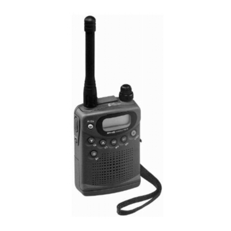
Maycom EH-465 User manual

MINI HAND HELD TYPE
UHF TRANSCEIVER
user’s manual
MODEL :EH-465
CONTENT
NEMO21 INFORMATION
& COMMUNICATIONS
FCC ID: O7MPRO-301
JOB # 106AK0
EXHIBIT # 9A-9W

3
INTRODUCTION ………………….………………..……………
4
GENERAL FEATURES ………………………………………… 4
DESCRIPTION OF FEATURES ……………………………… 5
1. TopPanel Features ……………………………..…………… 5
2. Side and BackPanel Features ……………………..……..…. 6
3. Bottom side Features ………………………………….……. 8
4. Display Panel Features …………………..…………………. 9
5. Front Panel Features ………………………………………. 11
FRS CHANNEL FREQUENCY TABLE ………….……...…. 14
CTCSS ……..……………………………………………..………
14
OPTION SETTING MODE …………………………..……… 15
BATTERY INSTALLATION ISTRUCTIONS ……………… 19
TO RECEIVE ..………………………………………….……… 20
TO TRANSMIT ..……………………………………………… 20
INITIALIZATION ..…………………………………………… 21
RANGE …………………………………………..…………..… 21
EASY AND COMMUNICATIONS ……………..…………… 21
SPECIFICATION ……………………………………………… 22
TROUBLESHOOTING ……………………………………… 23
INTRODUCTION

4
Congratulations on your purchase of the maycom EH-465
Advanced Family Radio Service (FRS) Portable radio. Your
maycom radio is designed to provide trouble-free service and
advanced user features to make it the premier choice in radio
communications.
GENERAL FEATURES
Compact size and light weight
Easy viewing multi-purpose LCD display
CPU controlled frequency synthesizer for reliable operation
CTCSS Tone Squelch system to avoid interference
Advanced user features – Vox, Scan, Call Tones, Melody Call
and Roger Beep
Operates on 4 AAA alkaline batteries, Ni-Mh Rechargeable
Battery Pack or DC Power Supply
Connections for optional accessories to enhance your
communication pleasure
Belt Clip and hand strap for easy carrying
FCC ID : O7MPRO-301
NEMO21 INFORMATION & COMMUNICATIONS
THIS DEVICE COMPLIES WITH PART 15 OF THE FCC RULES.
OPERATIONIS SUBJECT TITHE FOLLOWINGTWOCONDITIONS:
(1) THIS DEVICE MAY NOT CAUSE HARMFUL INTERFERENCE,
AND
(2) THIS DEVICE MUST ACCEPT ANY INTERFERENCE RECEIVED,
INCLUDING INTERFERENCE THAT MAY CAUSE UNDERSIRED
OPERATION.

4
DESCRIPTION OF FEATURES
1. Top Panel Features
1) Power On/Off, Volume Control
Turn the volume control clockwise to switch power on and
set volume to desired level. Turn the volume control
counter-clockwise to turn power off.
2) Antenna
The antenna is an integral part of FRS radio for maximum
performance. Do not modify or connect any external device
to antenna to change its characteristics.
3) Microphone and Speaker Jack
Jacks are provided for connection of optional
speaker/microphone maycom accessories.

5
2. Side and Back Panel Features
1) Flexible Wrist Strap
Placing the strap around the wrist will prevent the radio
from
falling to the ground(Strap is in accessory pouch).
2) PTT(Push-To-Talk) Button
Press the “PTT” button to activate the transmitter. Talk in a
normal voice about 2-3 inches from the front panel. When
external microphone is connected, the external PTT control
is activated. To receive, just release “PTT” button.
3) Lamp button
•Press the lamp button. The lamp will stay on during
pressing.
∙Monitor
Press Lamp button for a 2 sec in receiving mode, both
carrier and tone squelch circuit will be temporarily
disabled. Receiver/audio will sound on the loudspeaker
until the “Lamp” button is released.

6
∙Bell Feature
Function : The user is alerted to incoming calls by bell
indicator and an audible tone from the radio.
To Activate : Turn the power off
αPress the lamp button and then turn the
power on
βThe Bell icon “ ” will appear on the LCD.
Upon receiving an incoming call, the alert function will be
activated for about 8 seconds and then stopped for 15
trigger the alert device. The radio will automatically re-
armed and ready for another alert after the 15 seconds
timer expires.
To De-Activate : Turn the power off and on. The Bell icon
“ ” will disappear from the LCD.
4) Belt Clip
Allows for easy of carrying while attached to user’s belt.
(One screw and clip are in accessory pouch).
5) Battery Case
See “Battery Installation Instruction” for details.

7
3. Bottom side Features
1) DC Jack
For connection to AC Wall Charger, or optional Car
Cigarette Lighter DC power Supply Adaptor. Do not
connect
charger or power supply to the radio if you are using
Alkaline Batteries.
2) Bottom Charger contact for Desktop Charger
To charge the rechargeable battery pack with desktop
charger , this contact point will be used.

8
4. Display panel features
1) : : Indicates the “Key lock” feature has been activated.
2) : Indicates that radio is the “Transmit” mode.
3) SCAN : Indicates the “SCAN” feature has been activated.
4) PS : Indicates that the radio is in the “Battery save” mode.
5) : Displays the channel number in which the radio is
operating on.
6) : Displays the CTCSS tone number in which the radio
is
operating on.
7) : Indicates that “Beep” tone confirmation is on.
8) : Indicates that “Roger Beep” tone confirmation is on.
9) : Indicates that “Bell” feature has been activated.
10) : Indicates “TONE” is on.
11) : Indicates the amount of battery power left. If the
battery level is two low, “ ” will be flashing.
12) : Indicates the “VOX” feature has been activated.

9
13) : When transmitting, 10 segments will
appear on the LCD. “ ” icon will also
appear, at the top left corner of the LCD.
14) : Indicates that RF signal is being received.
15) : Indicates that a correct call is received in the
CTCSS
option mode.

10
5. Front Panel Features
1) Lock
This feature is allows the user to lock the operation of each
function button on the front panel.
•To Activate : Turn the power off.
αPress the Lock button and then turn the
power on
βThe “ ” icon will appear on the LCD to
indicate that this feature is currently
activated.
•To De-Activate : Repeat “To Activate” process. The “ ”
icon will disappear on the LCD.
2) Channel Down()
Press the Down(…) button to change the radio to operate
on
a lower channel number.
3) Down() Scan

11
This feature allows the user to call all 14 FRS channels for
activity. To start Down(…) scanning, press channel
Down(…) button over 2 seconds.
The radio will be stop on any busy channel until the preset
Scan delay time expires, then revert to scanning. The user
can cancel scanning by pressing the “PTT” while the radio
stops at a busy channel, and communicate with other users
using that channel. To activate Up(″) scanning, press
Up(″) channel button during down(…) scanning.
4) Melody Call Feature
The user can transmit two melody tones provided in the
radio to indicate its identify test audio performance of the
radio.
To operate, simply press “…(or ″)” button while holding
down the “PTT”
NOTE : FCC restrict the transmission of audible tones to
less than 15 seconds.
5) Tone On/Off
Press the “TONE” button while in the receiving mode to
toggle the Tone Squelch ON and OFF.
“TONE” icon will appear on the LCD when Tone Squelch is
switched ON.
•To De-Activate : Press “TONE” button one more time. The
“TONE” icon will disappear on the LCD.
NOTE : In Tone Squelch operation, the loudspeaker of the
receiver will only become a active while the
received signal has the same CTCSS code as the
one selected in the RX CTCSS Tone setting menu.
Although you could not hear interference or
transmissions from other users, they could still
exist
and may reduce your communication range. It is a
good practice to monitor the channel press the
“LAMP” button over 2 seconds, to ensure that it is
free of interference before you choose it for

12
communications.
Transmission in CTCSS is not private and is
subject
to monitoring by other users.
6) Channel Up()
Press the Up(″) button to move to a higher Channel.
7) Up() Scan
This feature allows the user to call all 14 FRS channels for
activity. To start Up(″) scanning, press channel Up(″)
button over 2 seconds. The radio will be stop on any busy
channel until the preset Scan delay time expires, then
revert
to scanning. The user can cancel scanning by pressing the
“PTT” while the radio stops at a busy channel, and
communicate with other users using that channel.
To activate Down(…) scanning, press Down(…) channel
button during Up(″) scanning.
8) VOX
This feature allows the user to transmit the voice without
pressing PTT button. In VOX mode, the transmitting will be
operated automatically when the signal is input to
microphone. If there is no signal to be input, the radio will
stay in the receiving mode.
•To Activate : Turn the power off
αPress Channel Up(″) button and then turn
the power on
βVOX “ ” will appear on the LCD.
•To De-Activate : Turn the power off and on.
9) Menu
Will be explained in Option Setting mode
10) Loudspeaker
High quality impact resistant output loudspeaker, which
provides clear, high volume reception.

13
11) Internal Microphone
The internal microphone is a front mounted, electrostatic
condenser microphone which provides clear high quality
audio transmission. For best results, hold the radio 2-4
inches from your mouth and speak in a normal voice.
FRS CHANNEL FREQUENCY TABLE
∂Display of channel
NO. Freq.(MHz) NO. Freq.(MHz)
1 462.5625 8 467.5625
2 462.5875 9 467.5875
3 462.6125 10 467.6125
4 462.6375 11 467.6375
5 462.6625 12 467.6625
6 462.6875 13 467.6875
7 462.7125 14 467.7125
CTCSS
The Continuous Tone Code System Squelch System (CTCSS)
is a system to avoid interfering signals on the same channel.
By selecting and enabling a code (or tone), only the proper
received signal will be enabled. The EH-465 can use the same
code for transmit and receive (Common Code).
∂ Display of CTCSS RX/TX Common Tone Setting Mode

14
In the above condition, press the “TONE” button over 2
seconds. CTCSS Tone Code will be blanking.
Press the “″or …” button to change the TX/RX Tone setting.
Press “PTT or TONE” button to store the selected CTCSS
code.
NO. Freq.(Hz) NO. Freq.(Hz) NO. Freq.(Hz)
1 67.0 14 107.2 27 167.9
2 71.9 15 110.9 28 173.8
3 74.4 16 114.8 29 179.9
4 77.0 17 118.8 30 186.2
5 79.7 18 123.0 31 192.8
6 82.5 19 127.3 32 203.5
7 85.4 20 131.8 33 210.7
8 88.5 21 136.5 34 218.1
9 91.5 22 141.3 35 225.7
10 94.8 23 146.2 36 233.6
11 97.4 24 151.4 37 241.8
12 100.0 25 156.7 38 250.3
13 103.5 26 162.2 39
When the LCD displays the CTCSS code desired, you can
change to display another CTCSS Tone setting by pressing
“TONE and ″or …” buttons. After all the settings are
completed, press “PTT or TONE” button to store your
selections. The radio will revert to normal operation. You can
then activate Tone Squelch operation by pressing “TONE”.

15
OPTION SETTING MODE
The following procedure allows the user to access optional
feature settings. To enter option setting mode, first turn off the
radio, then press and hold “TONE” button while turning on the
radio.
NOTE : While you are in the option setting mode :
A. If you press “TONE” button, the next option setting mode
will appear on the LCD.
B. If you press “PTT” button, all changed contents will be
stored and the radio will return to normal operation mode.
1. Setting of VOX Level(1-6 steps)
∂Display of VOX Level
Press ″or …button to change the VOX operating level from
1 to 6
2. Setting of VOX Delay time
∂Display of VOX Delay Time

16
This feature allows the user to limit the maximum VOX
delay
time for each transmission. If the VOX is depressed for a
period exceeding the VOX delay time, the VOX transmitter
will be cut off and the user has to release and press PTT
again to transmit.
Press ″or …button to change the VOX delay time from 1 to 6
3. Setting of Beep On/Off
This feature gives the user an audible test tone sequence
while turning the radio on, and short confirmation or error
tones when the user presses a button on the radio (Except
for PTT button).
∂Display of Beep On/Off
Press ″or …button to switch the “Beep” on and off. When
the Beep is on, the beep icon “ ” is on the LCD. The
feature
is preset “ON” at the factory. Confirmation tone is a high
pitch
tone indicating that the button selection is accepted.
4. Setting of Roger Beep On/Off
This feature allows the user to finish the transmitting and
the
Radio will be in the receiving mode.
When the Roger Beep is on, the Roger Beep icon “ ” is
on
the LCD.

17
∂Display of Beep On/Off
Press ″or …button to switch the “Roger Beep” on and off.
The feature is preset “ON” at the factory.
5. Setting of Power Save Mode
This feature enables power save circuit in the radio to
reduce
power consumption and increase the useful life of your
battery significantly in standby mode. The feature is preset
“ON” at the factory.
∂Display of Power Save On/Off Setting Mode
Press ″or …button to toggle power save On and Off.
The “PS” icon on the LCD will appear when power save
option is On. The icon will flash when the power save circuit
is in operation during standby mode.
6. Setting of Busy Lock On/Off
This allows the user to disable the transmitter while
receiving
a message from others. This will avoid interference on the
radio channel.
∂Display of Busy Channel Lock Out Setting Mode

18
Press ″or …button to toggle Busy Channel Lock Out
option between On and Off.
BATTERY INSTALLATION INSTRUCTIONS
1. Turn belt clip to right(or left) direction. (1)
2. Slide open the battery cover on the back of the radio
towards
the indicated direction. (2)
3. Install 4 AAA Alkaline batteries (or rechargeable battery
pack). If using individual batteries, place into the tray in the
indicated arrangement. Place tray inside battery well (3).
Please note the polarity of the batteries.
4. Put the battery cover back on the radio. Press and slide to
close. (4)
5. Press the battery open button upward to lock battery case.
If you have installed rechargeable “AAA” size batteries, or
used the Ni-Mh rechargeable pack, you can use the optional
DC wall charge adapter, or optional desktop charger to charge
the batteries.

19
NOTE : Alkaline RENEWABLE batteries are NOT regular
rechargeable batteries. They require a special battery charger
to recharge.
WARNING : DO NOT CHANGE ANY BATTERIES OTHER
THAN Ni-Mh RECHARGEABLE TYPE IN THE RADIO.
CHARGING BATTERIES INCORRECTLY CAN CAUSE
SERIOUS DAMAGE TO THE RADIO AND ITS OPERATOR.
TO RECEIVE
If you have just transmitted, release the “PTT” button. If you
have not transmitted, leave the radio on to receive selected
channel.
The radio will unmute upon receiving a signal. The BUSY icon
will appear on the LCD and the S-RF meter will show received
signal strength.
When the radio is operated with CTCSS Tone Squelch, and
the radio receives a signal with correct CTCSS code, the
CALL icon will appear on the LCD display.
TO TRANSMIT
Press and Hold the “PTT” button to transmit.
If Busy Channel Lock Out Option is on and the radio is in
receiving mode, “ ” will blinking on the LCD and the
audiable alarm (error beep tone) is telling you the radio will
stay in receiving mode and you will not be able to transmit.
Press “TONE” to cancel privacy codes on that channel.

20
NOTE : Please refer to the different sections in this manual for
detailed operational procedures.
INITIALIZATION
Pressing and holding the “PTT” while turning the power on will
put the radio into initialization mode. The radio will be reset to
original factory settings. This feature is useful when you have
mis-programmed the radio and the radio is not operating
normally.
RANGE
The maycom EH-465 has an effective range of about two
miles in open terrain. Buildings, hills, trees and other objects
can reduce the effective range of transmission.
EASY AND SAFE COMMUNICATIONS
The EH-465 can make communications with family and friends
easy and safe when :
You communicate with fellow hikers and bikers.
You keep track of children in a shopping mall or at a concert.
Communicate between floors or rooms in your own home.
Table of contents
Other Maycom Transceiver manuals