MAYEKAWA 160 GR User manual

160GR Natural Gas Booster Instruction Manual
Mayekawa all rights reserved. Subject to change without notice. Lat revised in October 2007 p.1
160 GR
Natural Gas Booster
Disassembly and Re-Assembly Instruction Manual
This manual is to provide instructions how to disassemble and re-assemble the 160GR machine.

160GR Natural Gas Booster Instruction Manual
Mayekawa all rights reserved. Subject to change without notice. Lat revised in October 2007 p.2
Contents
1. Introduction..........................................................................................................................................4
2. Capacity Control Procedures...............................................................................................................4
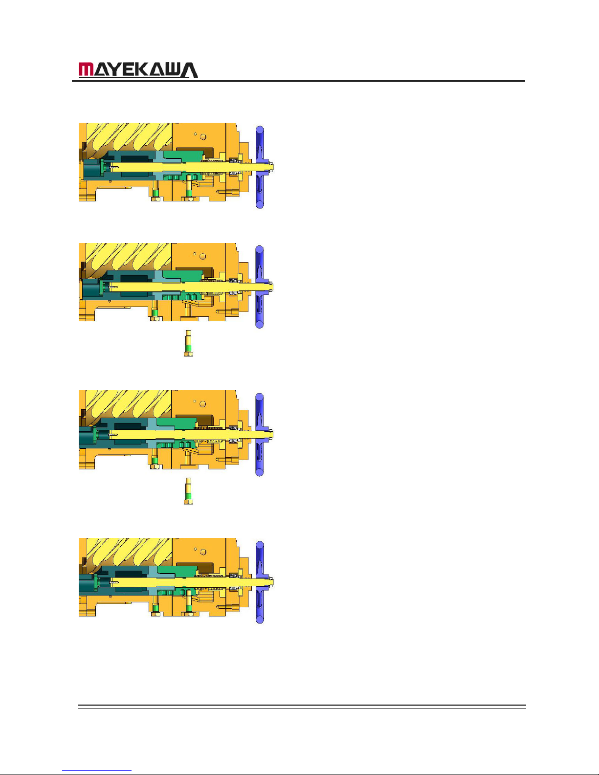
3. Variable Vi Structure ............................................................................................................................4
3.1.1 When the position of the current port is known......................................................................5
3.1.2 When the Current Port is not known ....................................................................................10
4. Parts Expanded View ........................................................................................................................13
4-1 160GR Standard .................................................................................................................13
4-2 160GR with Integral Pump ..................................................................................................14
4-3 Parts Structure Diagram......................................................................................................15
5. Parts List............................................................................................................................................17
6. Outer Dimension................................................................................................................................19
7. Disassembly ......................................................................................................................................20
Removing the Compressor..............................................................................................................20
7.1 Interior Gas Recovery ....................................................................................................20
7.2 Removing the connecting parts......................................................................................20
7.3 Suspending and Transferring the Compressor...............................................................20
7.4.1 Mechanical Shaft Seal....................................................................................................22
7.4.2 Unloader Cover ..............................................................................................................24
7.4.3 Unloader Thrust Bearing ................................................................................................25
7.4.4 Balance Piston Cover.....................................................................................................27
7.4.5 Unloader Spring Retainer...............................................................................................27
7.4.6 Balance Piston, Balance Piston Sleeve..........................................................................28
7.4.7 Speed up Gear Casing Cover ........................................................................................29
7.4.8 Speed up gear casing ....................................................................................................30
7.4.9 Disassembly of speed up gear parts on the driving side ................................................31
7.4.10 Spindle Roller Bearing....................................................................................................33
7.4.11 Disassembly of the speed up gear on the driven side ....................................................33
7.4.12 Thrust Bearing................................................................................................................34
7.4.12 Suction Cover.................................................................................................................36
7.4.13 Rotor, Rotor Casing, Variable Vi Slide Valve ..................................................................37
7.4.14 Bearing Head and Main Bearing ....................................................................................39
8. Re-assembly......................................................................................................................................40
8.1 Bearing Head and Main Bearing .........................................................................................40
8.2 Rotor Casing, Unloader Slide Valve, Variable Vi Slide Valve, Bearing Head.......................40
8.3 Rotor Casing, Rotor ............................................................................................................41
8.4 Suction Cover......................................................................................................................41
8.5 Thrust Bearings...................................................................................................................41
8.5 Installation of the driven side speed up gear .......................................................................42
8.6 Spindle Roller Bearings.......................................................................................................43
8.7 Building the Driving Side speed up Gear ............................................................................43
8.8 Installation of speed up Gear Casing ..................................................................................43

160GR Natural Gas Booster Instruction Manual
Mayekawa all rights reserved. Subject to change without notice. Lat revised in October 2007 p.3
8.9 Installation of speed up Spindle ..........................................................................................43
8.10 Speed up Gear Casing Cover .............................................................................................44
8.11 Balance Piston Cover..........................................................................................................44
8.12 Unloader Cover ...................................................................................................................44
8.13 Mechanical Shaft Seal ........................................................................................................45
9. Procedures to Adjust End Clearance.................................................................................................45

160GR Natural Gas Booster Instruction Manual
Mayekawa all rights reserved. Subject to change without notice. Lat revised in October 2007 p.4
1. Introduction
The 160GR is a compressor engineered for the natural gas booster. Provided that it will be
operated by an engine, the compressor itself has an internal speed up gear that allows
different ratios according to the required air volume.
Also, the Vi on the outlet port can be changed in 4 steps with the manual capacity control as
the standard.
2. Capacity Control Procedures
On the standard 160GR specification, the capacity control is done manually by a handle.
Turning the handle in clockwise is for loading, and turning it in counter-clockwise is for
unloading.
The slide valve for the capacity control is fully loading when it is in contact with the surface of
the variable Vi slide valve. The position of Unload is determined by the stopper equipped on
the surface of the under slide rod.
Therefore, the position of full-load of the slide valve depends on the selected Vi; therefore,
the strokes of the slide valve vary as well. The strokes of the slide valve for each Vi setting
are described below.
[CAUTIONS]
・ Although there are stopper structures on the full-load position and the minimum load
position, do not turn the handle with unnecessary force when attempting capacity control.
・ When loading, turning the handle with a relatively little force can easily move the slide valve.
When the slide valve is in contact with t
・ the variable Vi slide valve for full-load, the handle becomes heavy. Then, forcing the handle
to turn may lead to the internal damage.
・
Garph2.1 Strokes for Slide Valve for Each Vi
Vi Setting The number of rotation
Unload ⇒Full-Load
2.3 29‐1/2
2.63 26
3.65 21
5.0 17-1/3
3. Variable Vi Structure
To change the Vi on the outlet port, the size of the radial outlet port needs to be changed by
moving the variable Vi supplementary slide valve on the full-load.
The variable Vi supplementary slide valve is fixed to the case by fix pins through pin holes on
the Variable Vi slide valve. The pin holes are located to accommodate the 4 different Vi
settings so that the Vi can be changed step-by-step.
On 160GR, the fix pins of the Variable Vi slide valve are attached from the outside of the case.
When the pins are removed, the interior gas will be discharged to the air. When changing Vi

160GR Natural Gas Booster Instruction Manual
Mayekawa all rights reserved. Subject to change without notice. Lat revised in October 2007 p.5
settings, make sure that the compressor is at a stop and that the gas inside the compressor is
discharged in the air.
Vi should not be changed while the compressor is running.
To Change Vi Settings
[CAUTIONS]
・ On this compressor, Vi should be changed after the compressor is opened to the
atmosphere.
・ Vi settings should be changed while the compressor is stopped. Also, make sure the drive is
not moving or will not move.
・ The interior air pressure of the compressor needs to be equal to the air pressure before
proceeding with changing Vi settings.
Figure1: Variable Vi Structure Cut-up View
The compressor is set at the M port when shipped. Choose the most appropriate Vi setting
for the expected operating conditions.
When the appropriate port is to be other than the M port, the Vi setting needs to be changed
before operations. When the pressure conditions dramatically change during an operation,
the Vi needs to be changed to an appropriate setting.
There are 4 ports: H (Vi=5.0), M (Vi=3.65), L (Vi=2.63), K (Vi=2.3).
3.1.1 When the position of the current port is known
When the position of the current port is known, change the Vi setting by referring to
[Graph1] and choosing the appropriate number of rotations and the direction of the rotation.
a) Make sure the slide valve is on full-load on the current Vi condition (Turn the capacity
control handle in clockwise until it stops).

160GR Natural Gas Booster Instruction Manual
Mayekawa all rights reserved. Subject to change without notice. Lat revised in October 2007 p.6
b) Remove the guide pin from the case. When the current port is “K” or “L,” the guide pin is
located in the bottom area of the suction cover. When the current port is “M” or “K”, they
are located on the bottom of the rotor casing.
c) Turn the handle as many times as required to change to the desired Vi. When changing
to a higher Vi, turn the handle to the left. When changing to a lower Vi, turn the handle to
the left. For the number of rotations, refer to the Graph 2.1. Variable Vi valve can be
moved by turning the handle softly.
d) When changing the ports from the “K / L “ ports to the “M / H” ports, or vice versa, the plug
needs to be removed from the case and replaced with the Variable Vi valve fixing bolts.
e) On the “K” and “L” ports, the Variable Vi support guide pin should be attached to the
bottom of the suction cover. The plug should be attached to the bottom of the rotor
casing.
On the “M” and “H” ports, contrarily, the Variable Vi support guide pin should be attached
to the bottom of the rotor casing. The plug should be attached to the bottom of the suction
cover.
f) After moving the variable Vi slide valve, put the Vi guide pin into the case and lock them
with the hexagon socket head cap screws. With the Variable Vi support guide pin, use the
dice studs for the seal.
When the Vi guide pin feels heavy or caught by something, it should not be forced into the
holes. When this happens, it’s most likely that the position of the holes of the variable Vi
valve and that of the variable Vi valve fixing pin are not aligned. Slightly turn the handle to
the right or the left to find the position where the pin can be inserted smoothly.
g) When the variable Guide pin is smoothly inserted all the way, lock them by a proper
torque. Pun the dice stud for the seal in, and lock them in a different position from the
Variable Guide pin.
[CAUTION]
Head sizes of the variable Vi fixing bolts and the plug are not the same to avoid mistakes.
From the K port
K Port ⇒L Port K Port ⇒M Port K port ⇒H Port
Moving Distance
(mm)
21 50.5 72
Number of Rotations
of Handle
3-1/2 8-3/8 12
Direction of Rotations Counter-clockwise Counter-clockwise Counter-clockwise
Position of fixing pin Suction Cover Rotor Casing Rotor Casing
From the L Port
L Port ⇒K Port L Port ⇒M Port L Port ⇒H Port
Moving Distance
(mm)
21 29.5 51

160GR Natural Gas Booster Instruction Manual
Mayekawa all rights reserved. Subject to change without notice. Lat revised in October 2007 p.7
Number of Rotations
of Handle
3-1/2 4‐7/8 8-1/2
Direction of Rotations Clockwise Counter-clockwise Counter-clockwise
Position of fixing pin Suction Cover Rotor Casing Rotor Casing
From the M Port
M Port ⇒K Port M Port ⇒L Port M Port ⇒H Port
Moving Distance
(mm)
50.5 29.5 21.5
Number of Rotations
of Handle
8-3/8 4-7/8 3-5/8
Direction of Rotations Clockwise Clockwise Counter-Clockwise
Position of fixing pin Suction Cover Suction Cover Rotor Casing
From the H Port
H Port ⇒K Port H Port ⇒L Port H Port ⇒M Port
Moving Distance
(mm)
72 51 21.5
Number of Rotations
of Handle
12 8-1/2 3-5/8
Direction of Rotations Clockwise Clockwise Clockwise
Position of fixing pin Suction Cover Suction Cover Rotor Casing

160GR Natural Gas Booster Instruction Manual
Mayekawa all rights reserved. Subject to change without notice. Lat revised in October 2007 p.8
・Vi Changing Procedures < From K-Port to L-Port >
① the Position of K-Port
②Remove the Variable Vi guide pin.
③ Turn the capacity control handle 3 1/2 times
in counter-clockwise, and move the
Variable Vi slide valve to the L-port position.
④ Screw the Variable Vi guide pin in. If it is
tight, turn the handle slightly in both
directions and find a loose spot.
This completes the procedures for
changing to L-Port.

160GR Natural Gas Booster Instruction Manual
Mayekawa all rights reserved. Subject to change without notice. Lat revised in October 2007 p.9
・Vi Changing Procedures < From L-Port to M-Port >
① The position L-Port
② Remove the Variable Vi guide pin from the
bottom of the suction cover.
③ Turn the capacity control handle 4 7/8 times
in counter-clockwise and remove the set
bolt from the bottom of the rotor casing.
Replace it with Variable Vi guide pin.
④ Screw the Variable Vi guide pin into the
bottom of the rotor casing. If it is tight, turn
the capacity control handle slightly in both
directions.
⑤ Lock the set bolt into the bottom of the
suction cover.
This completes the procedures for
changing to the M Port.

160GR Natural Gas Booster Instruction Manual
Mayekawa all rights reserved. Subject to change without notice. Lat revised in October 2007 p.10
3.1.2 When the Current Port is not known
When the position of the current port is not known, move the Variable Vi valve to the
position of the stopper on the loading side. Then turn the handle as many times as
required in order to change to the desired Vi and move the Variable Vi valve.
a) Remove the Variable Vi support guide pin from the case. (The one with the larger
size of the hex head (30mm) is the guide pin.)
b) Turn the handle in clockwise until the Variable Vi valve touches the stopper.
c) According to Graph2.1, turn the capacity handle as many times as required in
counter-clockwise and move the Variable Vi support slide valve.
On the “K” and “L” ports, the Variable Vi support guide pin should be attached to the
bottom of the suction cover, and plug should be attached to the bottom of the rotor
casing.
On the “M” and “H” ports, contrarily, the Variable Vi support guide pin should be attached
to the bottom of the rotor casing, and the plug should be attached to the bottom of
the suction cover.
d) After moving the Variable Vi support slide valve, insert Vi support guide pin and lock
it with the hex bolt. Insert the dice stud for the seal into the Variable Vi support slide
valve before tightening it.
e) When the Vi guide pin feels heavy or caught by something, it should not be forced
into the holes. When this happens, it is most likely that the position of the hole of the
Variable Vi vale and that of the Variable Vi valve guide pin are not proper aligned.
Slightly turn the handle to the right or the left to find the position where the pin can
be inserted smoothly.
f) After the Variable guide pin is smoothly inserted all the way, lock it by a proper
torque. Put the dice stud for the seal in, and lock it at the position opposite to that of
the Variable guide pin.
[CAUTION]
・ If the turning handle feels heavy, do not force the handle to turn. This may result to
damage the stopper area.
・
K Port L Port M Port H Port
Moving Distance
(mm)
5 26 56 77.5
Number of Rotations
of Handle
13/16 4-3/8 9-3/8 12-15/16
Direction of
Rotations
Counter-Clockwise Counter-Clockwise Counter-Clockwise Counter-Clockwise
Position of guide pin Suction Cover Suction Cover Rotor Casing Rotor Casing

160GR Natural Gas Booster Instruction Manual
Mayekawa all rights reserved. Subject to change without notice. Lat revised in October 2007 p.11

160GR Natural Gas Booster Instruction Manual
Mayekawa all rights reserved. Subject to change without notice. Lat revised in October 2007 p.12
Each Port and the Position of the Variable Vi guide pin
K-Port
L-Port
M-Port
H-Port

160GR Natural Gas Booster Instruction Manual
Mayekawa all rights reserved. Subject to change without notice. Lat revised in October 2007 p.13
4. Parts Expanded View
4-1 160GR Standard

160GR Natural Gas Booster Instruction Manual
Mayekawa all rights reserved. Subject to change without notice. Lat revised in October 2007 p.14
4-2 160GR with Integral Pump

4-3
Maye
k
Parts Stru
16
k
awa all rights
cture Diag
r
0GR Natural
G
reserved. Su
b
r
am
G
as Booster
I
b
ject to chang
e
nstruction M
a
e
without notic
e
a
nual
e
. Lat revised
i
i
n October 20
0
0
7 p.1
5
5

Maye
k
16
k
awa all rights
0GR Natural
G
reserved. Su
b
G
as Booster
I
b
ject to chang
e
nstruction M
a
e
without notic
e
a
nual
e
. Lat revised
i
i
n October 20
0
0
7 p.1
6
6

160GR Natural Gas Booster Instruction Manual
Mayekawa all rights reserved. Subject to change without notice. Lat revised in October 2007 p.17
5. Parts List
No Name No Name
1 MAIN ROTOR CASING 43-1 THRUST BEARING GLAND M1
2 HEXAGON SOCKET HEAD CAPSCREW 43-2 THRUST BEARING GLAND M2
3 ALIGNMENT PIN 43-3 THRUST BEARING GLAND F1
4 43-4 THRUST BEARING GLAND F2
5 SUCTION COVER 44-1 STOP RING
6 GASKET, SUCTION COVER 44-2 STOP RING
11 BEARING HEAD 45 HEXAGONALHEAD BOLT
12 GASKET, BEARING HEAD 46 CONICALSPRING WASHERS
14 SPRING PIN 48 SEALRETAINER
18 HEXAGON SOCKET HEAD CAPSCREW 49 “O” RING
19 ALIGNMENT PIN 50 OIL SEAL
20 SPRING PIN 51 SEALCOVER
22 BALANCE PISTON COVER 52 GASKET, SEAL COVER
23 GASKET, BALANCE PISTON COVER 53 HEXAGON SOCKET HEAD CAP SCREW
24 HEXAGON SOCKET HEAD CAP SCREW SHAFT KEY
25 MALE ROTOR 100 MECHANICALSEALASSY.
26 FEMALE ROTOR 169 SPEED UP GEAR CASTING
27-1 MAIN BEARING M 170 GASKET, SPEED UPGEAR CASTING
27-2 MAIN BEARING F 171 SPEED UP GEAR CASTING COVER
28-1 SIDE BEARING M 172 GASKET, SPEED UP GEAR CASTING COVER
28-2 SIDE BEARING F 174 SPEED UP DRIVE GEAR
29-1 STOP RING 175 SPEED UP DRIVE GEAR KEY
29-2 STOP RING 176 SPEED UP GEAR SPACER
29-3 LABYRINTH SEALM 179 SPEED UP DRIVEN GEAR
29-4 LABYRINTH SEALF 180 SPEED UP DRIVEN GEAR KEY
30 BALANCE PISTON 181 SPEED UP DRIVEN GEAR SPACER
31 KEY, BALANCE PISTON 183 SIDE BEARING, SPEED UP GEAR
32 STOP RING 184 SPRING PIN
33 SLEEVE, BALANCE PISTON 185 ROLLING BEARING SPEED UP GEAR
34 SPRING PIN 186 STOP RING
35 “O” RING 187 STOP RING
38-1 THRUST BEARING M 188 SPEED UP GEAR SPINDLE
38-2 THRUST BEARING F 189 SPEED UP GEAR, THRUST BEARING
39-1 LOCK NUT 190 SPEED UP GEAR, THRUSTBEARING GLAND
39-2 LOCK NUT 191 GLAND BOLT
39-3 LOCK NUT 192 SPRING WASHER
40-1 LOCK WASHER 193 LOCK NUT
40-2 LOCK WASHER 194 LOCK WASHER
40-3 LOCK WASHER 195 HEXAGON SOCKET HEAD CAP SCREW
41-1 BEARING SPACER M 196-1 OILCONTROLTHROTTLE COMP MS

160GR Natural Gas Booster Instruction Manual
Mayekawa all rights reserved. Subject to change without notice. Lat revised in October 2007 p.18
No Name No Name
41-2 BEARING SPACER F 196-2 OILCONTROLTHROTTLE COMP FS
42-1 SPACER,THRUST BEARING MALIGNMENT 196-3 OILCONTROLTHROTTLE COMP MD
42-2 SPACER,THRUST BEARING FALIGNMENT 196-4 OILCONTROLTHROTTLE COMP FD
196-5 OIL CONTROLTHROTTLE, SPEED UP GEAR 237-C TORSIONALSLIP WASHER C
237-A TORSIONALSLIP WASHERA 237-D TORSIONALSLIP WASHER D
237-B TORSIONALSLIP WASHER B 237-E TORSIONALSLIP WASHER E
54 UNLOADER SLIDE VALVE (1) 196-5 OILCONTROL THROTTLE, SPEED UP GEARS
55 UNLOADER SLIDE VALVE (2) 246 UNLOADER SLIDE VAVLE GUIDE
58 HEXAGON SOCKET HEAD CAPSCREW 247 HEXAGON SOCKET HEAD CAP SCREW
67 UNLOADER PUSH ROD 248 SPRING WASHER
69 LOCK NUT 249 ALIGNMENT PIN
70 LOCK WASHER 273 HEXAGON NUT
74 UNLOADER CYLINDER COVER 280 PLAIN WASHER
75 GASKET, UNLOADER CYLINDER COVER 289 VI VARIABLE SLIDE VALVE
76 HEXAGON SOCKET HEAD CAPSCREW 326 SPRING HOLDER
79 THRUST WASHER 445 BUSH STOPPER
80 BEARING GLAND 446 SLIDING VALVE STOPPER
81 HEXAGON SOCKET HEAD CAPSCREW 452 HEXAGON SOCKET HEAD CAP SCREW
82 “O” RING 454-1 GUIDE PIN
83 SPRING 454-2 PLUG
84 SPRING RETAINER 455 HEXAGON SOCKET HEAD CAPSCREW
458 HEXAGON SOCKET HEAD CAPSCREW
523 “O” RING

160GR Natural Gas Booster Instruction Manual
Mayekawa all rights reserved. Subject to change without notice. Lat revised in October 2007 p.19
6. Outer Dimension

160GR Natural Gas Booster Instruction Manual
Mayekawa all rights reserved. Subject to change without notice. Lat revised in October 2007 p.20
7. Disassembly
Preparation
Although screw compressors are reliable machines, they need to be disassembled to have
their parts inspected after operating for a certain amount of time. In this chapter, the
procedures and instructions for disassembly and parts inspection will be provided.
Disassembling a compressor at the installed site is limited to: the shaft seal parts, the
unloader parts, and the balance piston parts. When the compressor is to be entirely
disassembled, the compressor needs to be removed from the mounting and placed in a
proper environment for disassembly.
Before the disassembly procedures, parts inspections and their handling, study this manual
and the actual compressor and understand the structure very well.
Tools for Disassembly
For disassembly process, properly use recommended tools for disassembly. The
recommended tools include special tools that need to be ordered from Mycom / Mayekawa
MFG.
As general tools, a hammer, a monkey wrench, a filer, and a sand paper (#800 and above)
will be required.
Other than the tools, you will need oil to wash the oil, new refrigeration oil, an oil can, a can
for drained oil, and waste cloth, etc. Use a large platen for the process, and choose a dry,
large environment with the least amount of dust or sand.
Removing the Compressor
7.1 Interior Gas Recovery
When the screw compressor is at a stop, the inside pressure of the compressor is very
high. Equalize the pressure with the lower pressure side. Then recover the gas to
equalize the pressure as the air pressure or a bit lower than that.
7.2 Removing the connecting parts
Make sure that the inside pressure of the compressor is the same as or a bit lower than
the air pressure before starting to remove parts.
Remove the connecting parts to the compressor, the coupling, the suction pipe, the
discharge pipe, refueling pipe, and the fixing bolt in series.
* When removing the refueling pipe (etc.), prepare a receiver for the residual oil that
overflows from the inside.
7.3 Suspending and Transferring the Compressor
The flange of the suction pipe is located on top of the compressor. Before suspending
the compressor, remove a part of it if the piping seems to interfere with the suspension.
Use the eyebolt on the bearing head and the two eyebolts on the suction cover to
suspend the compressor. When suspending, adjust the length with chain blocks etc. to
keep the compressor leveled.
In the preparation of disassembling the compressor entirely, have the compressor suspended
and remove the 4~6 hexagon socket head cap screws on the bottom of the casing which lock
Table of contents
Other MAYEKAWA Air Compressor manuals