manuals.online logo
Brands
  1. Home
  2. •
  3. Brands
  4. •
  5. Mayline
  6. •
  7. Indoor Furnishing
  8. •
  9. Mayline Ranger 7772 User manual

Mayline Ranger 7772 User manual

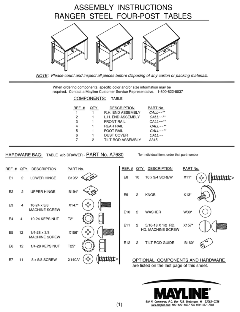
NOTE: Please count and inspect all pieces before
disposing of any carton or packing materials.
HARDWARE BAG
Part No. A7683 Ranger
Part No. A7684 Ranger with OPTIONAL Tool Drawer
TABLE *for individual item, order that part number
REF. # QTY. DESCRIPTION PART No.
E1 2 LOWER HINGE B195*
E2 2 UPPER HINGE B194*
E3 8 10-24 x 3/8 SCREW X147*
E4 8 10-24 KEPS NUT T2*
E5 12 1/4-28 x 3/8 SCREW X156*
E6 12 1/4-28 KEPS NUT T25*
E7 10 8 x 5/8 SCREW X140A*
E8 18 10 x 3/4 SCREW X11*
E9 2 BUMPER D10*
E10 2 LIFT ASSEMBLY V120A*
E11 4 10-32 x 1/2 FLAT HEAD SCREW X191*
E12 10 10-32 x 1/2 PAN HEAD SCREW X204*
OPTIONAL COMPONENTS HARDWARE:
The following hardware is in addition to the
Table Hardware .
TOOL DRAWER ACCESSORY:
E13 6 10-24 x 3/8 SCREW X147*
E14 4 10-24 KEPS NUT T2*
E15 1 HANDLE Q35*
E16 6 8-32 x 3/8 THRD. CUTTING SCREW X247*
E17 6 8-32 x 5/16 MACHINE SCREW X384*
E18 6 8-32 ACORN NUT T129*
ASSEMBLY INSTRUCTIONS
SPLIT TOP RANGER TABLE
** Denotes Color Code
COMPONENTS:
TABLE
REF. # QTY. DESCRIPTION PART No.
1 1 R.H. END ASSEMBLY A7560**
2 1 L.H. END ASSEMBLY A7559**
3 1 FRONT RAIL B7650**
4 1 REAR RAIL B7189**
5 1 FOOT RAIL B2026**
6 1 DUST COVER L4540
7 1 'H' FRAME A4011**
8 2 SUPPORT RAIL B6543**
OPTIONAL COMPONENTS:
The following components are in addition
to the TABLE components.
TOOL DRAWER ACCESSORY:
9 1 CENTER SUPPORT B7469**
10 2 DRAWER SLIDE B6361
11 1 TOOL TRAY F187
12 1 TOOL DRAWER A7553**
When ordering components, specific color information may be required.
Contact a Mayline Customer Service Representative. 1-800-822-8037
CATALOG No:
7772 7773
7772A 7773A
(1)
1. Place the two End Assemblies (1 & 2) upside.
Position the Front Rail (3) with notches 'UP'.
Position the Rear Rail (4) with the Dust Cover
attachment holes toward the floor. Secure these
Rails to the End Assemblies with two Screws
(E5) and two Nuts (E6) per end. DO NOT
tighten screws at this time.
2. Position the Foot Rail (5) with flat surface
toward the floor. Attach the Foot Rail to the End
Assemblies with four Screws (E5) and Nuts (E6).
TIGHTEN all rail attaching screws now.
3. Turn assembled table to an upright position.
MAYLINE recommends that two people perform
this task.
4. Attach the Support Channels (8) to the 'H'
Frame (7) using #10-32 x 1/2 Screws (E12).
Position the Frame with the diagonal holes for
the top hinge attachment to the front. Position
each Support Channel with the 7/8 notch to the
front. Frame should be flush with the top of the
Support.
5. Place the 'H' Frame/Support Assembly into
position and attach it to the Front and Rear Rails
using #10-24 x 3/8 Screw (E3) and KEPS Nuts
(E4).
6. Attach Lower Hinge (E1) to 'H' frame with
#10-32 x 1/2 Thread Cutting Screw (E12).
Position with hinge slot toward front of table.
Diagonal holes
toward FRONT
Smaller (7/8) NOTCH
toward FRONT
all Supports
Right Support
CHANNEL FACE
Left Support
CHANNEL FACE
FRONT of TABLE
(2)
FRONT
Tab toward front edge
FRONT of TABLE
7. Attach the Upper Hinges (E2) to the underside of
the Tilt Top with #10 x 3/4 Particle Board Screws
(E8). Position with the hinge tab toward the front
edge of the top.
8. Attach Lift Assembly (E10) to the 'H' Frame cross
rail with #10-32 x 1/2 Flat Head Screws (E11).
9. Install the Tilt Top onto the table. Insert the
upper hinge tab into the slot of the lower hinge.
Raise the Lift Assembly and align the holes in the lift
with the holes in the top. Attach with #10 x 3/4
Particle Board Screws (E8).
10. Attach the Reference Top to the base with #10 x
3/4 Particle Board Screws (E8) through the front and
rear rail and through the side flange.
11. Attach Dust Cover (6) to base with #8 x 5/8
Screws (E7).
12. Attach top Bumpers (E9) to Dust Cover with #10
x 3/4 Screw (E8). Position approximately as show.
Measured from edge of dust cover.
FRONT of TABLE
(3)
1. Separate the Drawer Slides (10) into two pieces. Extend the
Slide to the full extension. Remove the smaller portion (10B) by
pressing the plastic release and pulling.
2. Attach the large Slide portion (10A) to the Center Support (9)
using two Screws (E16). Begin attaching the Slide using the large
'Horizontal' slot in the last mounting tab.
3. Attach one large Slide portion (10A) to the brackets on the R.H.
side of the table using two Screws (E16). Begin attaching the
Slide using the large 'Horizontal' slot in the last mounting tab.
4. Attach the smaller Slide portion (10B) to each side of the
Drawer body using three Screws (E17) and three Acorn Nuts
(E18). Begin attaching the Slide using the 'Vertical' slot in the first
hole cluster.
5. Install the Handle (E15) onto the Tool Drawer head using
Screws (E13).
6. Install the assembled Center Support into the Base. Attach the
Support with two Screws (E13) and two Nuts (E14) per rail.
7. Install the drawer into the assembled table.
(4)

This manual suits for next models

3

Other Mayline Indoor Furnishing manuals
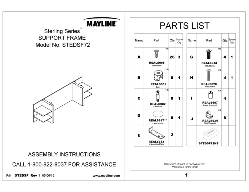
Mayline Medina Series User manual

Mayline

Mayline Medina Series User manual

Mayline A7680 User manual

Mayline

Mayline A7680 User manual

Mayline CSII BRIDGE User manual

Mayline

Mayline CSII BRIDGE User manual

Mayline realoffice Aberdeen Series AB2S36 User manual

Mayline

Mayline realoffice Aberdeen Series AB2S36 User manual

Mayline RealOffice Aberdeen Series User manual

Mayline

Mayline RealOffice Aberdeen Series User manual

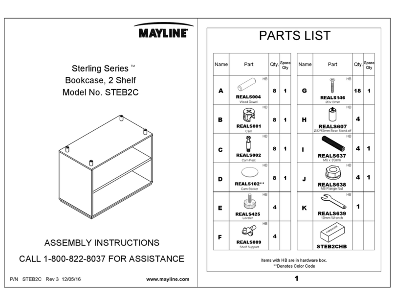
Mayline Sterling Series User manual

Mayline

Mayline Sterling Series User manual

Mayline Sterling Series User manual

Mayline

Mayline Sterling Series User manual
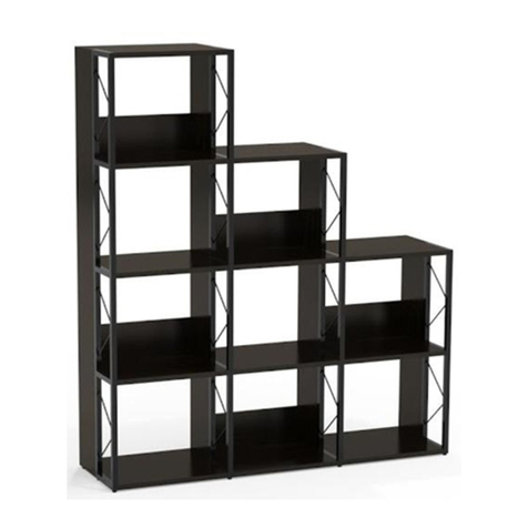
Mayline 1001VTL User manual

Mayline

Mayline 1001VTL User manual

Mayline UL330MBLK User manual

Mayline

Mayline UL330MBLK User manual

Mayline Realoffice Aberdeen Series User manual

Mayline

Mayline Realoffice Aberdeen Series User manual

Mayline e*LAN WORKSTATIONS 24" SERVER STATION 2... User manual

Mayline

Mayline e*LAN WORKSTATIONS 24" SERVER STATION 2... User manual

Mayline Sterling Series User manual

Mayline

Mayline Sterling Series User manual
Mayline MAYTRIX LAN FURNITURE 90 DEGREES CORNER WORK... User manual

Mayline

Mayline MAYTRIX LAN FURNITURE 90 DEGREES CORNER WORK... User manual

Mayline CSII FREESTANDING PENINSULA C625 User manual

Mayline

Mayline CSII FREESTANDING PENINSULA C625 User manual

Mayline Medina Series User manual

Mayline

Mayline Medina Series User manual

Mayline i705 User manual

Mayline

Mayline i705 User manual

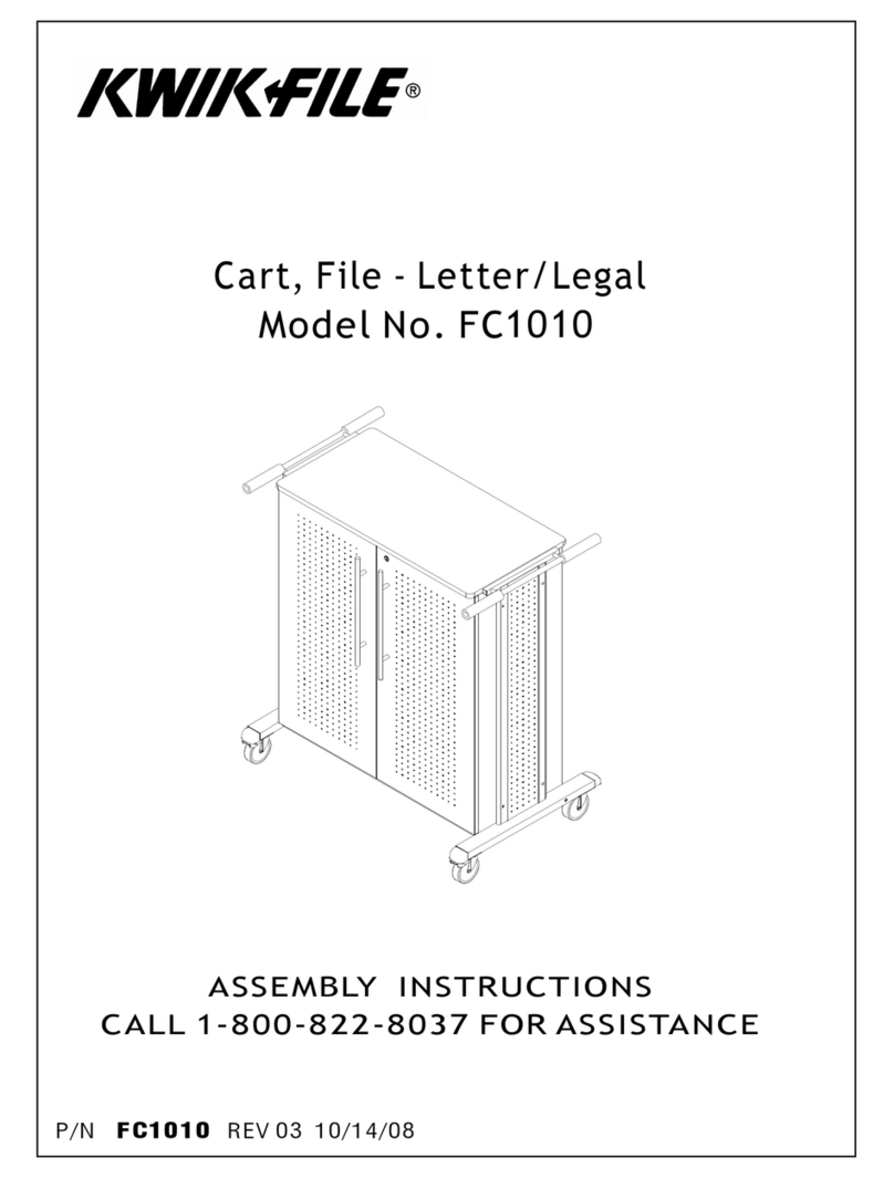
Mayline Kwik File FC1010 User manual

Mayline

Mayline Kwik File FC1010 User manual

Mayline Medina Series User manual

Mayline

Mayline Medina Series User manual
Mayline 1001VTG User manual

Mayline

Mayline 1001VTG User manual

Mayline Medina Series User manual

Mayline

Mayline Medina Series User manual

Mayline 5 COLUMN CRNR XR BASE User manual

Mayline

Mayline 5 COLUMN CRNR XR BASE User manual

Mayline Sterling Series User manual

Mayline

Mayline Sterling Series User manual

Mayline Medina MNRR User manual

Mayline

Mayline Medina MNRR User manual

Mayline CSII TILT TOP RETURN User manual

Mayline

Mayline CSII TILT TOP RETURN User manual

Popular Indoor Furnishing manuals by other brands

Regency LWMS3015 Assembly instructions

Regency

Regency LWMS3015 Assembly instructions

Furniture of America CM7751C Assembly instructions

Furniture of America

Furniture of America CM7751C Assembly instructions

Safavieh Furniture Estella CNS5731 manual

Safavieh Furniture

Safavieh Furniture Estella CNS5731 manual

PLACES OF STYLE Ovalfuss Assembly instruction

PLACES OF STYLE

PLACES OF STYLE Ovalfuss Assembly instruction

Trasman 1138 Bo1 Assembly manual

Trasman

Trasman 1138 Bo1 Assembly manual

Costway JV10856 manual

Costway

Costway JV10856 manual
moss DESIGN Caisson Credenza Assembly instructions

moss DESIGN

moss DESIGN Caisson Credenza Assembly instructions

Aquaglide FULL DECK 15.0 owner's manual

Aquaglide

Aquaglide FULL DECK 15.0 owner's manual

AREBOS AR-HE-SW30 user manual

AREBOS

AREBOS AR-HE-SW30 user manual

Till-Hilft Fulda 87005.330 Assembly instructions

Till-Hilft

Till-Hilft Fulda 87005.330 Assembly instructions

Twoey Outside 2010 quick start guide

Twoey Outside

Twoey Outside 2010 quick start guide

Hettich Easys 200 operating instructions

Hettich

Hettich Easys 200 operating instructions

The bedboss RELAX 404 Series owner's manual

The bedboss

The bedboss RELAX 404 Series owner's manual

Oeseder Möbelindustrie Bern 991 720 Assembly instructions

Oeseder Möbelindustrie

Oeseder Möbelindustrie Bern 991 720 Assembly instructions

Costway HW68469 user manual

Costway

Costway HW68469 user manual

Next ALIX A27743 Assembly instructions

Next

Next ALIX A27743 Assembly instructions

BROSA Hans Assembly guide

BROSA

BROSA Hans Assembly guide

Prodigg MINIKA PBA015T-FUR installation manual

Prodigg

Prodigg MINIKA PBA015T-FUR installation manual

manuals.online logo
manuals.online logoBrands
  • About & Mission
  • Contact us
  • Privacy Policy
  • Terms and Conditions

Copyright 2025 Manuals.Online. All Rights Reserved.