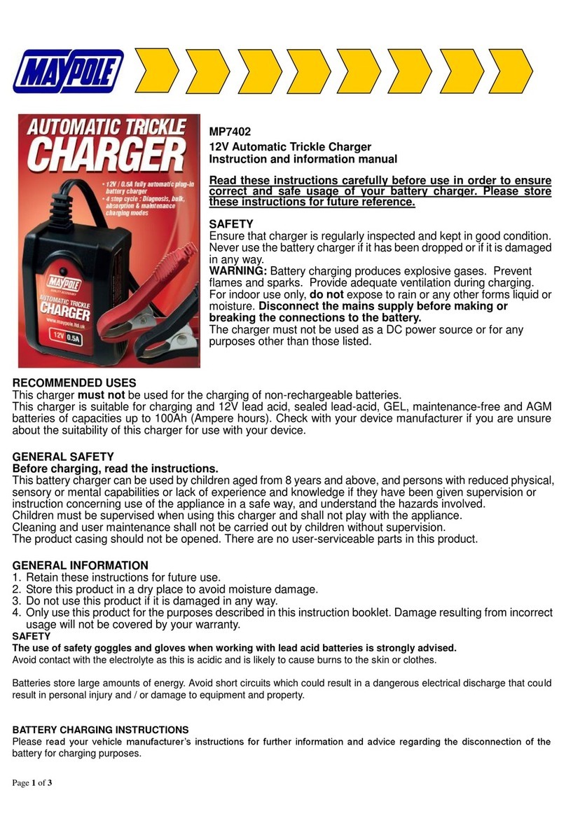
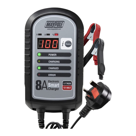
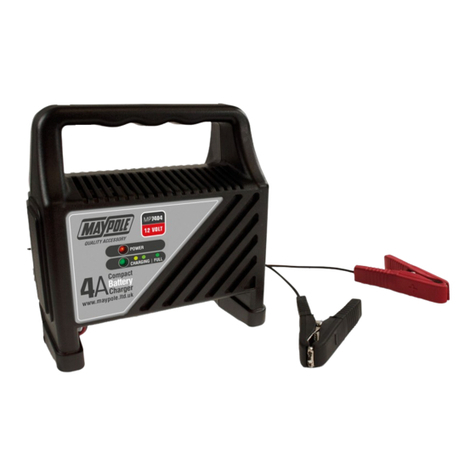
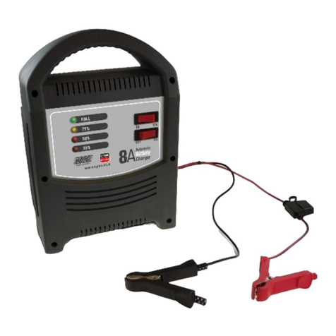
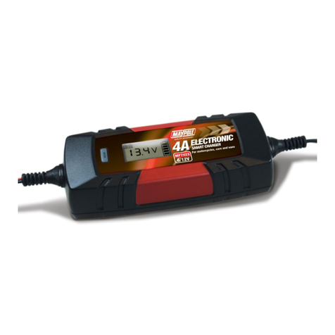
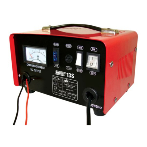
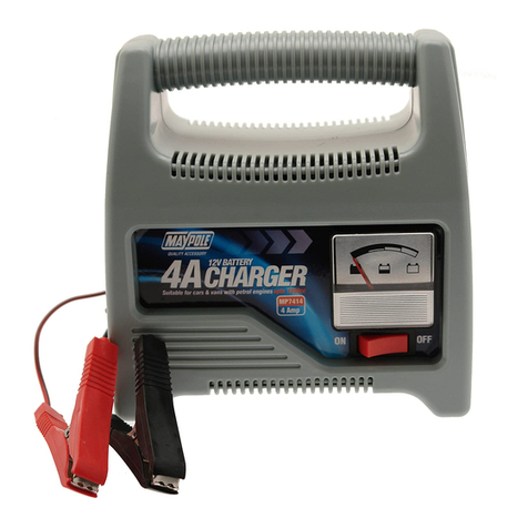
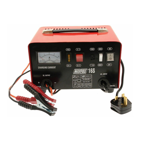
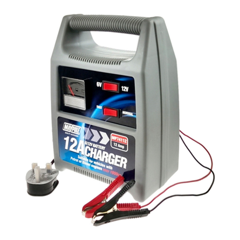
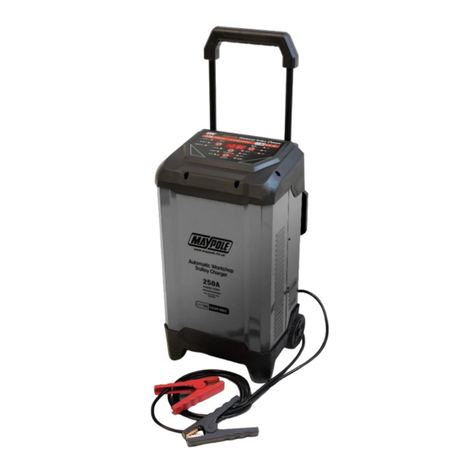
MayPole MP7212 User manual

DDDDDDDDDDDww
w.maypole.ltd.uk
MAMMMMMMMMM
pole.ltd.uk
www.maypole.ltd.uk
1
MP7212 MP7220
3 Amp Slow Charge 3 Amp Slow Charge
75 Amp Engine Start12V 150 Amp Engine Start 12V
12 Amp Fast Charge 12V 20 Amp Fast Charge 12V
6 Amp Fast Charge 24V 12 Amp Fast Charge 24V
Fully automatic processor controlled. Suitable for all 12 or 24 Volt lead-acid
batteries including deep cycle, AGM and Gel.
INSTRUCTION MANUAL
Please read and follow this operating manual and all safety instructions for the batteries to be
charged and the vehicle before using this device.
Keepthese instructions for future reference.
When passing the device on to others be sure to also include
all documentation. The
instruction leaflet is
also
available on our website:
www.maypole.ltd.uk
12A and 20A Automatic Workshop Chargers

DDDDDDDDDDDww
w.maypole.ltd.uk
MAMMMMMMMMM
pole.ltd.uk
www.maypole.ltd.uk
2
RISK OF FIRE OR EXPLOSION
•
Explosive gases may escape during charging. This is normal, but please follow the
following
guidelines:
•
Do not charge near flames or sparks –do not smoke in the area.
•
Ensure adequate ventilation during charging.
•
Keep the charging area completely clear of combustible materials.
•
Do not leave charging batteries unattended for long periods or overnight.
•
Do not allow battery to overheat by exceeding 400C.
•
Store and use indoors only, do not expose to rain or moisture.
•
The charger is designed to charge 12V or 24V Lead-Acid, AGM & GEL batteries with
capacities
as shown in the specifications table.
•
Charge only one battery at a time.
Do not use with non-rechargeable batteries.
WARNING –GENERAL SAFETY
•
Never attempt to charge a frozen battery or dry cell battery.
•
This charger should not be used as a continuous DC power source or for any purposes other
than those listed –any other use will invalidate warranty.
•
Ensure that cables are regularly inspected and kept in good condition. Never use the cable to
carry or pull the device.
•
Never use the appliance if the charger has been dropped or if the charger, mains lead, plug, output
leads or crocodile clips are worn or damaged.
•
In order to avoid a hazard, replacement of the mains cable should only be carried out by the
manufacturer. There are no user-serviceable parts in this product other than the fuse in the
plug.
•
Locate the charger as far away from the battery being charged as the cables will permit.
•
The use of an extension cord is NOT recommended. lf an extension cord must be used ensure
that the capacity of the cable is greater than the rating of the charger
•
Be sure to position the power cord to prevent it from being stepped on, tripped over or damaged.
•
Never place charger directly above battery being charged, gases from the battery will corrode
and damage the charger.
•
Always disconnect mains supply before connecting and disconnecting the battery leads.
•
Follow instructions for safe use –electrical discharge from batteries can be dangerous.
•
Battery electrolyte is acidic and likely to cause burns. The use of safety goggles and
gloves
when working with lead acid batteries is strongly advised.
•
Remove metal items such as rings, necklaces and watches while working with batteries.
•
This appliance is not for use by a person (including children) with reduced physical, sensory or
medical capabilities or lack of experience or knowledge.
•
NOTE: A marine battery installed in a boat must be removed and charged on shore. To charge it on
board requires equipment specially designed for marine use.
The manufacturer is not responsible for damages caused by:
•
Exterior force, damage to the device and / or damage to parts of the device caused by
mechanical impact or overload.
•
Consequential damages caused by non-intended and / or improper use, and / or defective
batteries.
•
The unauthorised opening of the device will void the guarantee.
1
2

DDDDDDDDDDDww
w.maypole.ltd.uk
MAMMMMMMMMM
pole.ltd.uk
www.maypole.ltd.uk
3
Product Overview
No. Description / Function
1 Main Display –Displays the value of selected charging parameter.
2 4 x Charging Voltage and Current LEDs - Indicate the selected charging voltage and
current. Switched with the button (4).
3 ENGINE START LED - Illuminated when the 12v jump starting function is activated by
repeatedly pressing button(4)
4 CHARGE RATE selection button for selecting the charging current and charging voltage.
5 CHARGED LED - lights up when the battery is fully charged.
6 CHARGING LED - lights up during charging.
7 REVERSE POLARITY LED - lights up if connected incorrectly or a charging error occurs.
8 DISPLAY MODE BUTTON button - switches the parameters (V / A / %) shown On the
Main display (1).
9 BATTERY TYPE button - switches battery types (charging mode only).
10 STANDARD / AGM / GEL LEDs - Display the selected battery type (charging mode only).
11 V / A / % LEDs - display the selected charging parameter (in charging mode only) switched
with the DISPLAY MODE button (8).
3

DDDDDDDDDDDww
w.maypole.ltd.uk
MAMMMMMMMMM
pole.ltd.uk
www.maypole.ltd.uk
4
DESCRIPTION OF LED INDICATORS AND DISPLAY
The charger starts with the MAIN DISPLAY (1) in the AMPS mode.
Pressing the DISPLAY MODE button (8) repeatedly will allow you to cycle through to the other
modes, VOLTAGE and BATTERY CAPACITY % . The LEDs (11) will indicate which mode is
selected, the digital display will indicate the corresponding value for each mode.
DESCRIPTION OF MAIN DISPLAY MODES
•VOLTS
The display will show the charging voltage supplied by the charger, this is usually higher than the
battery's resting voltage.
•AMPS
This mode shows the charging current being supplied by the charger and not the charge rate
selected. The charger detects and delivers the correct amount of amperage needed to charge the
connected battery.
•%
Battery capacity is the approximate percentage of the full battery capacity. At less than 50%
battery capacity, the MAIN DISPLAY will read LO.
As the battery is charged the display will increase in 10% increments between 50% and 90%
capacity. At full charge, the display will read FUL.
PREPARATION OF THE BATTERY
Refer to the vehicle manufacturer’s handbook for battery maintenance and charging guidelines.
If the battery must be removed from the vehicle before charging, ensure all other electrical loads
in the vehicle are switched off. Always disconnect the earthed connector from the battery first.
CONNECTION
Always disconnect the mains supply before making or breaking battery connections. Ensure the
battery poles are clean. Connect the battery clips to the battery in the following order:
First connect the positive charging lead (RED) to the positive post of the battery
(marked +, +ve or P).
Then for vehicles with the battery still installed: connect the negative charging lead (BLACK)
to
the vehicle chassis (marked -, -ve or N), well away from the battery, fuel line, hot
or moving parts.
For batteries removed from the vehicle: Connect the negative charging lead (BLACK) to the
negative post of the battery (marked -, -ve or N).
After connecting the clips, rotate them slightly so as to remove any dirt or oxidization, thus
ensuring a good contact. The charger must now be connected to the mains supply.
CHARGING
Warning! When correctly connected to a battery and to the mains supply, the charger will detect
the battery voltage (12V-24V) and display the voltage measured on the “Main Display” (1).
Charging will then start automatically, always commencing with the slow charge rate for the
detected Voltage and Standard Battery type.
This will illuminate one of Charging Voltage and Current display LEDs (2) and the Standard
battery type LED in display (10).
The “CHARGING” LED (6) will light up, the charging process is then fully automatic.
Note:
Verify the device’s pre-set charging voltage (12V or 24V) corresponds with the connected battery.
The charger is equipped with a microprocessor (MCU - Micro Computer Unit) and features fully
automatic diagnostic, charging, and maintenance functions. If the wrong battery voltage is set or
the battery is defective, it will not continue to charge and the “REVERSE POLARITY”LED (7) will
light up (also see “Troubleshooting”).
6
5
4
7

DDDDDDDDDDDww
w.maypole.ltd.uk
MAMMMMMMMMM
pole.ltd.uk
www.maypole.ltd.uk
5
CHARGING RATE SELECTION
Do not overcharge a battery, refer to the battery manufacturers charging instructions.
The charger always starts up in the AUTOMATIC slow charge mode.
Repeatedly pressing the CHARGING RATE MODE button (4) will allow you to cycle through the
following charging programs:
3A Intended Use for slow charging automotive batteries or charging motorcycle batteries.
Fast Charge: Intended Use for charging medium automotive batteries. Faster charging of small-
to-medium capacity automotive, marine, deep cycle, and farm tractor batteries
Engine Start 12V - 75A or 150A: Intended Use Helps start vehicles and equipment with a weak
battery.
During Charging: You may repeatedly press the DISPLAY MODE button (8) to display the
Charging voltage (V), Charge in (%) and the Charging current (A). You may also repeatedly press
the BATTERY TYPE button (9) to select the battery type.
MAINTENANCE MODE
Once the battery is fully charged, the “CHARGED” LED (5) will light up and the “Charging” LED (6)
goes out, the charger will automatically go into Maintenance (Float) mode to maintain the charge
in the battery and protect from overcharging. This function allows the charger to be permanently
connected.
WHEN CHARGING IS COMPLETE
To disconnect the charger, first switch off the mains supply, unplug the charger from the mains
socket and then disconnect the clips in the following order:
Remove thenegative (BLACK lead) first. Then disconnect the positive (RED lead) from the
battery.
ABORTED CHARGES
lf charging cannot be completed normally, charging will be aborted.The digital display may show
an Error code. To reset the charger after an aborted charge, unplug the charger, disconnect the
battery and then after checking the battery and connections reconnect correctly.
OVERHEAT PROTECTION
The charger is designed to shut itself off if overheating is detected. Once the charger cools down, it
will resume charging automatically.
ENGINE START FUNCTION
The charger’s engine start function (3) can be used to help start vehicles with a weak battery. In
very low temperatures or if the battery voltage is below 1.5 V charge the battery at least 5 minutes
before jump starting.
1. Connect the charger as described under “Connection”.
2. When charging commences, repeatedly press the CHARGE RATE button (4) to select
“ENGINE START” mode LED (3).
The display shows the current battery voltage. The battery will be charged at 5 A until the engine
is started.
Note: The engine start mode will automatically stop after approx. 30 seconds to prevent damage
to the device.
3. Try starting the vehicle.
Note: Try starting for max. 5 seconds. Wait approx. 3 minutes before trying to start it again to
allow the charger and battery to cool down.
4. Engine start mode will be disabled for 3 minutes. The display will show a 180 second
countdown and the battery will be charged at 5 A until the engine is start mode is available.
5. Once the engine has started, unplug the mains plug from the 230 V mains socket.
6. Disconnect the black (-) terminal connection cable with clamp from the negative battery
terminal.
7. Disconnect the red (+) terminal connection cable with clamp from the positive battery terminal.
13
8
9
11
10
12

DDDDDDDDDDDww
w.maypole.ltd.uk
MAMMMMMMMMM
pole.ltd.uk
www.maypole.ltd.uk
6
TROUBLE SHOOTING AND FAULT CODES
Check that the mains supply is connected and the display is illuminated. Check that the clips are
correctly connected to the battery and making a good contact. The only user serviceable part is the
mains fuse fitted inside the mains plug. The battery must be in good condition and capable of
accepting a charge.
Error/Problem
Possible cause
Correction
Display (1) shows
"---".
No battery connected.
Battery voltage below 0.5 V.
Connect battery (see “Connecting the
Device").
Unable to charge battery.
Display (1) shows
"Er1".
Connected battery
incompatible.
Only connected compatible batteries
(see
“Intended Use").
Display shows (1)
"Er2".
Connected battery defective.
Dispose of battery in an
environmentally friendly manner.
Display (1) shows
"Er3".
The battery was not fully charged
within 24 hours.
• Verify the charging rate is set
correctly.
• Battery defective.
“Reverse Polarity”
LED (7) lit
Battery incorrectly/not connected
Unplug charger and check the
connections.
Incorrect battery voltage
(12/24V) selected
Unplug charger and wait for the LEDs to
go out. Reconnect the charger and
select the correct battery voltage.
Battery cannot be
charged
No power supply
Battery defective
Verify the charger is connected to a
230V mains socket.
Long charging time
Battery temperature too low
Never charge a frozen battery.
Charging rate increases with battery
temperature.
Battery capacity too high.
Use a different charger
Low charging current selected
Select higher charging current
Battery voltage too
low
Battery charging period too
short
Increase duration of battery charging
period
Cleaning, care and maintenance
Clean clamps after every charge to prevent corrosion, wipe off any battery fluid which may have
come into contact with the clamps.
Clean the product with a soft, dry cloth. Store the machine in a clean, dry place.
Disposal: Do not throw electrical appliances in with domestic waste!
In accordance with European Directive 2012/19/ EC for waste electrical and electronic equipment
(WEEE) must be collected separately and taken to a recycling point for disposal.
16
15
14

DDDDDDDDDDDww
w.maypole.ltd.uk
MAMMMMMMMMM
pole.ltd.uk
www.maypole.ltd.uk
7
TECHNICAL SPECIFICATIONS
Model
No.
Input
Max. Charging
Output
Engine
Start
For Battery
Capacity
Fuse
Mains Plug
MP7212
230V AC 50Hz 180 Watt
12V DC 3A / 12A
24V DC 3A / 6A
75A
12V 6-200 Ah
24V 6-100Ah
13A
MP7220
230V AC 50Hz 270 Watt
12V DC 3A / 20A
24V DC 3A / 12A
150A
12V 6-300 Ah
24V 6-150Ah
13A
We declare that this product conforms to the following standards
EN60335-1:2012+A11:2014+A13:2017
EN60335-2-29:2004+A2:2010, EN62233:2008.
EN55014-1:2017, EN55014-2:2015, EN61000-3-2:2014,
EN61000-3-3:2013, and the following Directives 73/23 CEE, 93/68 CEE,
2004/108/EC, 2002/95/EC (ROHS)
Technical Manager Maypole Ltd November 2018
Email: sales@maypoleltd.co.uk
Web: www.maypole.ltd.uk
17
This manual suits for next models
1
Table of contents
Other MayPole Batteries Charger manuals

MayPole
MayPole MP726 User manual

MayPole
MayPole MP716 Quick setup guide

MayPole
MayPole MP7423 User manual

MayPole
MayPole MP7108 User manual

MayPole
MayPole MP7104 User manual

MayPole
MayPole MP713 Quick setup guide

MayPole
MayPole MP7423 User manual

MayPole
MayPole MP7414 User manual

MayPole
MayPole MP7403 Quick setup guide

MayPole
MayPole MP7418 User manual
Popular Batteries Charger manuals by other brands

Black & Decker
Black & Decker BDV080 user guide

Blu
Blu Power Dock Ultimate 4x Fast Charging Station Product Instruction

Coleman
Coleman 2 WATT SOLAR 12 VOLT BATTERY MAINTAINER user manual

Hyperion
Hyperion NET Series user manual

AlzaPower
AlzaPower A133 user manual

Digitus
Digitus DA-10084 Quick installation guide