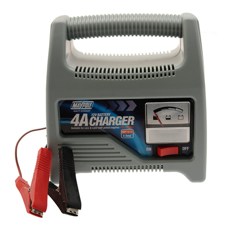
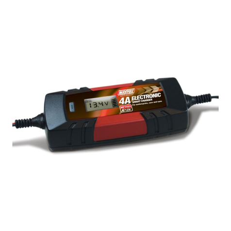
MayPole MP7423 User manual

(MAY,DII/
UK's
Leading Towing & Touring Company
Electronic
Smart
Charger
MP7423 6V/12V
4A
INSTRUCTION
MANUAL
(D@)@@@
Keep these instructions
for
future reference. A more detailed instruction leaflet is
available on
our
website: www.maypole.ltd.uk

SAFETY -Important Guidelines
RISK OF EXPLOSION
Explosive gases may escape during charging. This is normal,
but
please follow the
following guidelines:
• Do
not
charge near flames or sparks -
do
not
smoke
in
the area.
• Ensure adequate ventilation during charging.
• Keep the charging area completely clear of combustible materials.
Do not allow battery
to
overheat by exceeding 40°C.
Store and use indoors only.
The charger is designed
to
charge 6v and 12v Lead-Acid & AGM batteries with
capacities 1.2Ah
to
120Ah (Ampere hours) only. Charge only one battery at a time.
Do not use with non-rechargeable batteries.
This charger should not be used as a continuous DC power source or for any
purposes other than those listed -any other use will invalidate warranty.
• Ensure that cables are regularly inspected and kept
in
good condition.
Never use the appliance if the charger, mains lead, plug, output leads or crocodile
clips are damaged.
• Replacement of the mains cable should only be carried out
by
the manufacturer.
There are no user-serviceable parts
in
this product other than the fuse
in
the
output
and
inputieads.
• Always disconnect mains supply before connecting and disconnecting the
battery leads.
• Follow instructions for safe use -electrical discharge from batteries can
be dangerous.
• Battery electrolyte is acidic and likely
to
cause burns. The use
of
safety goggles and
gloves when working with lead acid batteries is strongly advised.
• This appliance is not for use by a person (including children) with reduced physical,
sensory
or
medical capabilities or lack
of
experience or knowledge.

FEATURES & TROUBLESHOOTING
2 LCD DISPLAY
During charging the LCD display backlight will be red, when charging
is
finished it will
turn green.
LCD Display Key:
1. 12V standard lead-acid battery mode.
2. 12V AGM battery mode.
3. Winter mode for 12V
STD
battery and 12V AGM batteries. Suitable for 5°C or less.
4.
6V
standard lead-acid battery mode.
5. Battery level indicator. Each bar represents approximately 20%. The outline border
flashes during charging. When the battery
is
full & during float charging the border
and
all
five bars will be visible.
6. Battery voltage indicator, accurate to
0.1
V.
7. Reverse polarity indicator.
8. Bad battery indicator.
9. Clamp connection indicator.
1 2 3 4 5
I
121s11111121
AGMI
*I
&1
s,;
I
6
,~,,~,
,~,
o,:e.o
V
~
g
::,c
-
7 8 9
Display Fault Action
Battery
polarity
reversal
symbol
Battery
clamps
reversed
.
Disconnect
and
reconnect
displayed.
correctly.
Clamp
indication
and
voltage
Dirty
or
oxidized
battery
Clean
terminals.
symbols
displayed.
terminals
.
Low
or
unstable
charging
current.
No
Display.
Mains
supply
not
connected
.
Check
socket.
Display
back
light
on
,
display
Battery
not
connected.
Check
clamps,
replace
battery.
showing
O.OV
and
clamp
symbol.
Bad
battery
indicator.
Battery
beyond
recovery.
Battery
requires
replacement.
Clamp
connection
indicator
.
Indicates
poor
connection.
Check
clamps.
Output
lead
fuses
should
be
checked
and
replaced
as
necessary
(SA
blade)
in
connection
with
all
faults.
Also
check
the
fuse
in
the
mains
plug
,
which
should
only
be
replaced
with
a
3A
BS1362
fuse
.
Persistant
fuse
replacement
may
indicate
a
fault
with
the
charger
or
leads.
Check
these
before
each
use
and
do
not
use
if
worn
or
damaged.

INSTRUCTIONS FOR USE
3 SUMMARY OF OPERATION
Step
1
Step
2
Step
3 Step4
Step
5
Pulse
charging
.
Soft
start.
Auto-Select
Current
Absorption.
Float
charging
.
&
Bulk
Charging.
12VSTD
Connect
the
charger
to
the
Every
15
to
20min
the
14.4V
consta
nt
Charger
will
det
ect
th
e
batte
ry's
mode
battery
,
the
charger
will
detect
charger
will
check
the
voltage
voltage
again
the
battery
's
voltage
battery
voltage
.
If
the
Maximum
Cha
r
gi
ng
automatically
.
voltage
has
i
ncreased
by
voltage
current
ste
ps
(1)
tt
the
voltage
falls
below
12V
.
1121101
0.
2V
or
more
the
charging
1
4.4V
down
by
1A
at
Battery
fa
u
lt
is
sh
own
.
(1
)
If
a
voltage
of
more
than
current
will
remain
the
a
time
until
1A
(2)
tt
voltage
is
12
to
13
.2V,
cha
r
ger
7.5Vis
detected
,
the
charger
same
.
If
the
voltage
has
is
reached.
will
swttch
to
maintenanc
ech
argi
ng
recognizes
battery
as
12V
not
increased
by
0.
2V
the
(3)
tt
the
voltage
is
m
ore
than
1
3.2
V
12VAGM
(2)
If
a
voltage
of
7.
5V
to
10
.
5V
is
1A
charging
charger
will
increase
the
14.8V
consta
nt
charge
rw
ill
watt
for
th
ev
olta
geto
mode
found
,
maintenance
charge
is
until
the
charging
current
by
1A
voltage
fall
before
starting
am
ai
nt
enan
ce
activated
voltage
to
2A
.
The
cycle
will
be
Maximum
Cha
r
ging
charge
.
(0.
8A
pulse
charging
until
voltage
reaches
repeated
every
15
to
voltage
current
steps
11211&1!
exceeds
10
.
5V)
12.8V
20min
.
and
the
charging
14.8V
dow
n
by
1A
at
a
(3)
If
the
voltage
doesn
't
reach
current
can
be
increased
time
un
til
1A
10.5V
within
30
minutes
,a
to
3A
or
4A.
This
charging
is
reache
d.
12VWinter
battery
fault
is
indicated
.
cycle
will
contin
ueu
ntil
14
.8
Vc
on
s
tant
mode
the
battery
vo
l
tage
M
aximum
vol
ta
ge
reaches
the
maxim
um
vol
t
age
Cha
rg
i
ng
value.
curre
nt
is
fa
lli
ng
*
14.8V
un
ti
l
1A
.
.:.
Connect
-
the-charger
to
the
--·_,_
-Every
15
to
20min
the
--
Charger
will
d
etect
the
batte
ry
's
battery
,
the
charger
will
detect
charger
will
check
the
v
oltage
agai
n
the
battery
's
voltage
battery
voltage
.
If
the
(1)
tt
the
vo
ltage
fall
s
below
6V
.
automatically
;
voltage
has
increased
by
B
att
ery
fa
ult
is
s
hown
.
(1)
If
voltage
of
less
than
7.
5V
is
0.
2V
or
more
the
charging
(2)
tt
the
vo
ltag
e
is
6to6
.6V
,
6VWinter
detected
the
charger
recognizes
current
will
remain
the
charger
will
swttc
htomai
nten
a
nce
the
battery
as
6V
same.
If
the
voltage
has
charging
.
mode
(2)
If
voltage
of
1.5V
to
5V
is
1A
chargin
g
not
increased
by
0.
2V
the
(3)
tt
the
volta
ge
is
more
than
6.
6V
until
the
Maximum
found
,
maintenance
charge
is
voltage
charger
will
i
ncrease
the
voltage
char
gerw
ill
wa
tt
f
or
th
e
voltage
to
l&VSTil
activated
reac
h
es
charging
current
by
1A
7.2V
fall
befores
ta
rti
ng
a
ma
i
ntenan
ce
(0.
8A
pulse
charging
until
voltage
6.4
V
to
2A
.
The
cycle
will
be
charge.
exceeds
5.
25V)
repeated
every
15
to
(3)
if
voltage
doesn
't
reach
5.
25V
20min
.
and
the
charging
with
in
30
minute
s,
a
battery
faul
t
current
can
be
increased
is
i
nd
i
cated
to
3A
or
4A
.
This
charging
cycle
will
continue
until
the
battery
voltage
reaches
7.
2V
1.
Preparation of battery
Refer to the vehicle manufaturer's handbook for battery maintenance guidelines.
2.
Charging lead selection
Interchangeable
ring
terminal and fully-insulated battery clip charging leads are supplied.
• Select the appropriate lead for your application. Quick fit
ring
terminal leads are
useful for applications where the battery
is
not easily accessible
(e.g. some motorcycles).
• Attach to the charger output lead using the quick-fit connector (fitted to each).
This must be done before connecting the charger to either the mains supply or
to the battery.

CONNECTION
Always disconnect the mains supply before making or breaking battery connections.
Connect the battery clips or ring terminals to the battery
in
the
foll<;>wing
order:
1. Connect the positive charging lead
(RED)
to the positive post of the battery
(marked + , +ve or
P).
2. For vehicles with the battery still installed: connect the negative charging lead (BLACK)
to
the vehicle chassis (marked - , -ve or
N),
well away from the battery, fuel line, and hot
or moving parts.
For batteries removed from the vehicle: Connect the negative charging lead (BLACK) to the
negative post of the battery (marked - / -ve
or
N).
After connecting the clips, rotate them slightly so as to remove any dirt or oxidization, thus
ensuring a good contact.
CHARGING
WARNING! DO NOT ATTEMPT
TO
START
THE
VEHICLE WITH THE CHARGER
CONNECTED
TO
THE
BATTERY.
THIS
MAY DAMAGE YOUR BATTERY CHARGER.
Switch
on
the mains power supply. For 12V batteries select the charging mode appropriate
for your battery by pushing the MODE button. The display will cycle through the available
options (12V
STD,
12V AGM, WINTER). The charger will now automatically measure the
voltage of your battery and diagnose its condition. For 6V batteries the charger will
automatically commence the
6V
STD charging program.
WHEN CHARGING IS COMPLETE
Switch off the mains supply, unplug the charger and disconnect the clips from the battery,
negative (BLACK lead) first. Then disconnect the
(RED)
positive lead from the battery.
Or,
if used, disconnect the ring terminal charging lead
in
the same way. If desired, this lead
can be left permanently attached to a vehicle battery, but the end-cap must be fitted to
the quick-fit connector at
all
times
to
prevent short circuit, sparks or dirt and water entry.
When not
in
use the charger should NOT be left connected to this lead.
TECHNICAL SPECIFICATIONS
Protection class
IP65
Input voltage
230V 50Hz
Input current Output
0.6A
12V:4A
6V:4A
TECHNICAL SPECIFICATIONS
Max lead-acid battery
capacity
1.2-120Ah
We
declare that this product conforms to the following standards EN60335-1 ,
EN60335-2-29, EN55014, EN61000, and the following Directives 73/23
CEE,
93/68
CEE
,
2004/108/EC, 2002/95/EC
(ROHS)
~~C!J&-
Technical Manager
Maypole Ltd
January 2017
email: [email protected]
web: www.maypole.ltd.uk
/MAfllll)
UK's Leading
Towing
&
Touring
Company
Table of contents
Other MayPole Batteries Charger manuals

MayPole
MayPole MP7404 User manual

MayPole
MayPole MP716 Quick setup guide

MayPole
MayPole MP7403 Quick setup guide

MayPole
MayPole MP7423 User manual

MayPole
MayPole MP7418 User manual

MayPole
MayPole MP7428 Quick setup guide

MayPole
MayPole MP7402 Quick setup guide

MayPole
MayPole MP7104 User manual

MayPole
MayPole MP7212 User manual

MayPole
MayPole MP7414 User manual