MayPole MP726 User manual

pg. 1
MP726 MP727
5/15/30/40A Charge. 250A Engine Start 20/30/40/60A Charge. 350A Engine Start
Fully automatic processor controlled. Suitable for all 12 or 24 Volt batteries including lead-
acid, deep cycle, AGM and Gel.
Please read and follow this operating manual and all safety instructions
carefully when using this device to charge batteries or to start a vehicle.
Keep these instructions for future reference.
When passing the device on to
others be sure to also include all documentation.
The instruction leaflet is also
available on our website: www.maypole.ltd.uk
Automatic Workshop Trolley Chargers
Instruction Manual

pg. 2
RISK OF FIRE OR EXPLOSION
Explosive gases may escape during charging. This is normal, but please follow the
following guidelines:
Do not charge near flames or sparks –do not smoke in the area.
Ensure adequate ventilation during charging.
Keep the charging area completely clear of combustible materials.
Do not leave charging batteries unattended for long periods or overnight.
Do not allow battery to overheat by exceeding 400C.
Store and use indoors only, do not expose to rain or moisture.
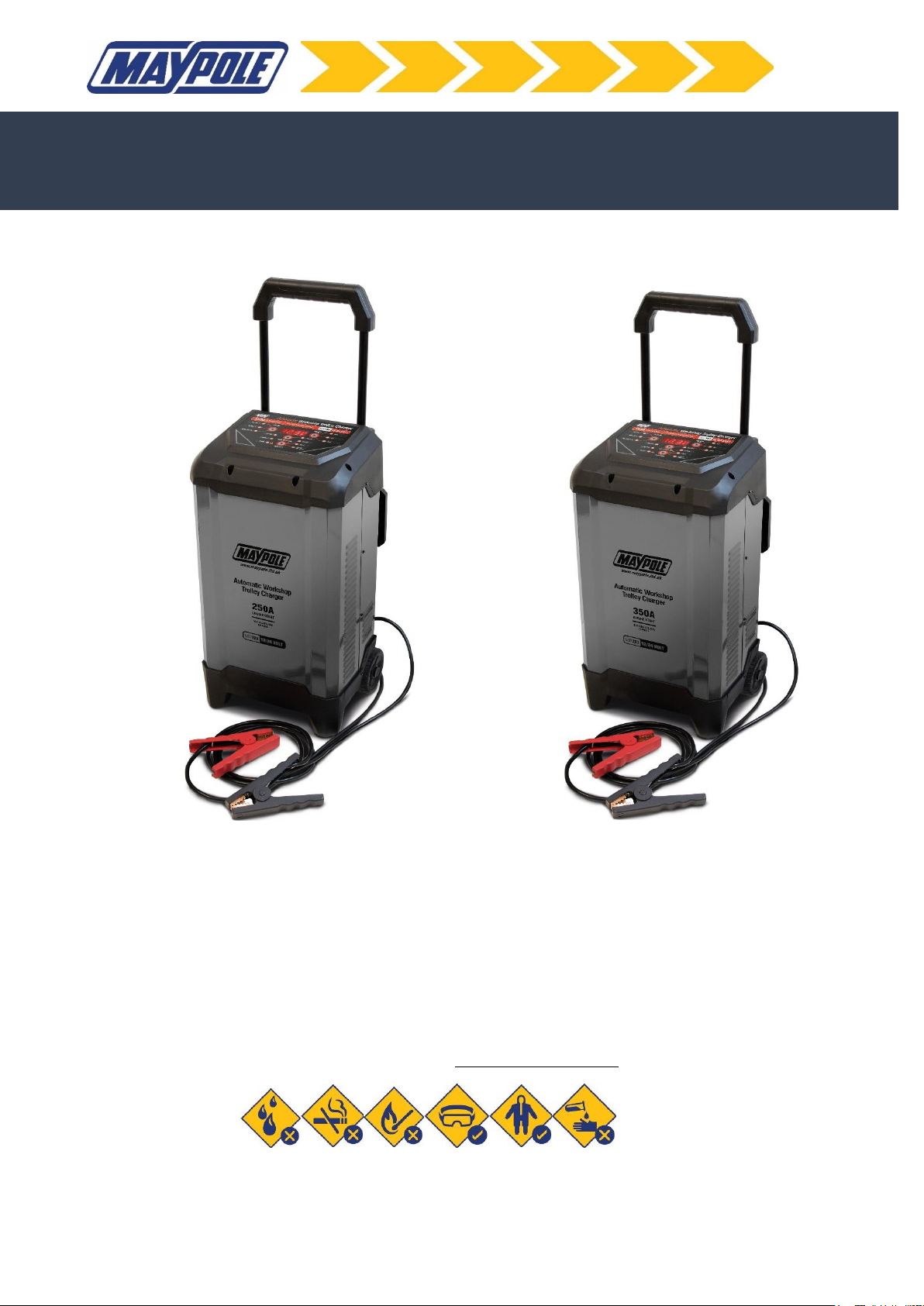
The charger is designed to charge 12V or 24V Lead-Acid, AGM & GEL batteries with
capacities as shown in the specifications table.
Charge only one battery at a time.
Do not use with non-rechargeable batteries.
WARNING –GENERAL SAFETY
Never attempt to charge a frozen battery or dry cell battery.
This charger should not be used as a continuous DC power source or for any purposes
other than those listed –any other use will invalidate warranty.
Ensure that cables are regularly inspected and kept in good condition. Never use the
cable to carry or pull the device.
Never use the appliance if the charger has been dropped or if the charger, mains lead,
plug, output leads or crocodile
clips are worn or damaged.
In order to avoid a hazard, replacement of the mains cable should only be carried out by
the manufacturer. There are no user-serviceable parts in this product.
Locate the charger as far away from the battery being charged as the cables will permit.
The use of an extension cord is NOT recommended. lf an extension cord must be used
ensure that the capacity of the cable is greater than the rating of the charger
Be sure to position the power cord to prevent it from being stepped on, tripped over or
damaged.
Never place the charger directly above the battery being charged, gases from the
battery will corrode and damage the charger.
Always disconnect the mains supply before connecting and disconnecting the
battery
leads.
Follow instructions for safe use –electrical discharge from batteries can be dangerous.
Battery electrolyte is acidic and likely to cause burns. The use of safety goggles and
gloves when working with lead acid batteries is strongly advised.
Remove metal items such as rings, necklaces and watches while working with batteries.
1
2

pg. 3
This appliance is not for use by a person (including children) with reduced physical,
sensory or medical capabilities or lack of experience or knowledge.
NOTE: A marine battery installed in a boat must be removed and charged on shore. To charge
it on board requires equipment specially designed for marine use.
The manufacturer is not responsible for:
Consequential damages caused by non-intended and / or improper use, and / or
defective batteries.
The unauthorised opening of the device will void the guarantee.
PRODUCT OVERVIEW
No. Description / Function
1Main digital display –shows charging status
2Display mode button –switches the parameters (Voltage/ Battery % &
Alternator %) shown on the main display (1)
3Voltage/ Battery % & Alternator % LED’s – indicate the selected charging
parameter
4Charged LED –lights up when the battery is fully charged
5Charging LED –lights up during charging
6Error LED –lights up if connected incorrectly or cannot charge battery (see
trouble shooting)
7Battery type selector button –switches battery type (STD/ GEL/ AGM)
8STD/GEL/AGM LED’s – indicate the selected battery type
9Current rate selector button –switches the charging current
10 Current LED –lights up when changing the current rate selection (9)
11 Function selector button –switches between charge / engine start & repair
functions
12 Charge LED –indicates charging function is selected
13 Start LED –indicates start function is selected
14 Repair LED –indicates repair function is selected
3

pg. 4
DESCRIPTION OF DISPLAY INFORMATION
When connected to a battery press the “DISPLAY”button (2) until the following LED is
illuminated:
Voltage LED illuminated
When no charging function is selected, the display will show the battery’s resting
voltage.
Battery % LED illuminated
During the charging cycle, the display will show the estimated charge percentage of the
battery.
Alternator % LED illuminated
When the charger is NOT charging; start the vehicle and turn on the vehicle’s
headlights. The alternator percentage range is from 0% to 100%. Readings below 0%
will read LO, readings above 100% will read HI. If you get a HI or LO reading have the
vehicles electical system checked by a qualified technician.
The below information is a detailed explaination of the 10 stage charging process:
STEP 1: ANALYSING 1 (Checks if battery has connected with the charger)
STEP 2: DESULPHATION (Pulsing charging to remove sulphate)
STEP 3: SOFT START (Charges with gradually increasing charging current)
STEP 4: CONTROLLED CURRENT CHARGE (Adjusts the charging current intelligently)
STEP 5: ANALYSING 2 (Tests if the battery can absorb charge)
STEP 6: CONSTANT OUTPUT CHARGE (Charges with constant voltage and compensates fake full charge
caused by high current charging)
STEP 7: RECOVERY CYCLE CHARGE (Absorbs more charge and compensates side effect of reduced
charging current)
STEP 8: ABSORPTION (Charges with constant trickle current for maximum battery voltage)
STEP 9: ANALYSING 3 (Tests if the battery can hold charge)
STEP 10: MAINTENANCE (Continuously monitors the battery, and charges with trickle current once the
voltage is lower than threshold)
4

pg. 5
CONNECTION TO MAINS SUPPLY
MAINS SUPPLY
The electrical supply required for this product is in excess of 13 amp, NO plug is fitted.
You must therefore contact a qualified electrician to ensure that a suitable power
supply is available. We recommend the use of an industrial round pin plug and socket
(IEC60309) this should be discussed with your electrician. Use of an RCD to protect this
circuit is recommended.
MAINS PLUG
This charger must be correctly earthed via a three-pin plug, as shown.
a) Connect the green/yellow earth wire to the earth terminal.
b) Connect the brown live wire to live terminal ‘L’.
c) Connect the blue neutral wire to the neutral terminal, ‘N’ or unmarked.
d) After wiring, check that there are no bare wires, that all wires have been correctly
connected, that the external insulation extends beyond the cable restraint and that
the restraint is tight.
EXTENSION CABLES
If an extension reel is used it should be fully unwound before connection. The cable
conductor core section is important and should be at least 1.5mm² for MP726 and
2.5mm² for MP727, use of long extension cables will also affect performance and the
shortest suitable length should be selected.
HANDLE INSTALLATION
To install the handle - pull the clamp storage panel found on the rear of the charger
upwards to remove it. Press the spring clips on the handle and insert into the 2 holes
on the rear of the charger. Ensure the spring clips are fully locked into the retaining
holes. The handle can be fully retracted for compact storage.
To remove the handle –use a tool (ie screwdriver) to press the spring clips into the
retaining holes. Pull the handle out of the 2 holes on the rear of the charger.
Max. input power
charging
Max input power -
engine start
Recommended fuse
or circuit breaker
MP726
1.5Kw
6.0Kw
16 Amp
MP727
3.0Kw
9.0Kw
32 Amp
5
6

pg. 6
PREPARATION OF THE BATTERY
Refer to the vehicle manufacturer’s handbook for battery maintenance and charging
guidelines.
If the battery must be removed from the vehicle before charging, ensure all other
electrical loads in the vehicle are switched off. Always disconnect the earthed
connector from the battery first.
CONNECTION
Always disconnect the mains supply before making or breaking battery connections.
Ensure the battery poles are clean. Connect the battery clips to the battery in the
following order:
First connect the positive charging lead (RED) to the positive post of the battery
(marked +, +ve or P).
Then for vehicles with the battery still installed: connect the negative charging lead
(BLACK)
to the vehicle chassis (marked -, -ve or N), well away from the battery, fuel
line, hot
or moving parts.
For batteries removed from the vehicle: Connect the negative charging lead (BLACK) to
the
negative post of the battery (marked -, -ve or N).
After connecting the clips, rotate them slightly so as to remove any dirt or oxidization,
thus ensuring a good contact. The charger must now be connected to the mains
supply.
CHARGING
When correctly connected to a battery and to the mains supply, the charger will detect
the battery voltage (12V-24V) and display the voltage measured on the “Main Display”
(1).
Select the correct battery type “Battery Type” (7).
Select an appropriate current rate “Current rate selector” (9).
Select charge on the “Function selector” (11).
The “Charging LED” (5) will light up, the charging process is fully automatic. The digital
display provides information on the 10 stage charging process.
To stop charging press the “Function selector” (11). The “Charging LED” (5) will go out
and the digital display will read ‘CHARGE-OFF’.
The “Charged LED” (4) will light up when charging is complete. The charger will
automatically go into Maintenance mode (step 10) to maintain the charge in the
battery and protect from overcharging. This function allows the charger to be
permanently connected.
7
8
9

pg. 7
Note –when charging the “Battery Type button” (7) will not work
WHEN CHARGING IS COMPLETE
To disconnect the charger, first switch off the mains supply, unplug the charger from the
mains socket and then disconnect the clips in the following order:
Remove thenegative (BLACK lead) first. Then disconnect the positive (RED lead) from
the battery.
ABORTED CHARGES
lf charging cannot be completed normally, charging will be aborted.The digital display
may show an Error code. To reset the charger after an aborted charge, unplug the
charger, disconnect the battery and then after checking the battery and connections
reconnect correctly.
OVERHEAT PROTECTION
The charger is designed to shut itself off if overheating is detected (see trouble shooting).
Once the charger cools down, it will resume charging automatically.
ENGINE START FUNCTION
The charger’s “engine start function” (13) can be used to help start vehicles with a weak
battery. In very low temperatures or if the battery voltage is below 1V it is better to
allow pre-charging of the battery for at least 4 minutes before jump starting.
1). Connect the charger as described under “Connection”.
2). Press “Function Selector” (11) until the “Start” (13) LED indicator is illuminated.
3). Crank the engine until it starts or 5 seconds pass. If the engine does not start, wait 4
minutes before cranking again. This allows the battery and charger to cool down.
4). During the engine start process the “digital display” (1) will show START READY –the
charger is waiting for the engine to be cranked before delivering the amps for the
engine start.
5). Once cranking is detected, the charger will automatically deliver up to its maximum
output required by the starting system for up to 5 seconds.
6). After cranking the charger enters a mandatory 240 seconds cool down state. The
“digital display” (1) indicates the remaining cool down time in seconds. After 240
seconds the “digital display” (1) will show START-READY.
10
11
12

pg. 8
7). Once the engine has started, unplug the mains plug from the 230 V mains socket.
8). Disconnect the black (-) terminal connection cable with clamp from the negative
battery terminal.
9). Disconnect the red (+) terminal connection cable with clamp from the positive
battery terminal.
REPAIR FUNCTION
The charger’s “repair function” (14) can be used to to repair old, idle or sulphated
batteries. Not all batteries can be recovered. If possible for optimum results take the
battery through a full charging cycle before using this function. This mode uses a high
charging voltage and may cause some water loss in WET cell batteries. As some
batteries and electronics may be sensitive to high charging voltages, it is advised to
disconnect the battery from the vehicle before using this mode.
1). Connect the charger as described under “Connection”.
2). Press “Function Selector” (11) until the “Repair” (14) LED indicator is illuminated.
This will be a solid light. The “digital display” (1) will show REPAIR ON.
3). The repair function will last for 8hrs. If the battery can be repaired the charger will
automatically enter the 10 stage charging process.
4). To stop repairing press the Function Selector” (11) again and the “Repair” (14) LED
indicator will go out. The “digital display” (1) will show REPAIR OFF
The charger will automatically enter repair mode if it detects an old, idle or sulphated
battery. The “digital display” (1) will show REPAIR ON and the “Repair” (14) LED
indicator will flash yellow.
13

pg. 9
TROUBLE SHOOTING & FAULT CODES
Check that the mains supply is connected and the display is illuminated. Check that the
clips are correctly connected to the battery and making a good contact. The battery must
be in good condition and capable of accepting a charge.
Error/Problem
Possible cause
Correction
Display (1) shows EO1 &
Error LED (6) is illuminated
Inccorect connection
Ensure connection process is
followed correctly
Display (1) shows EO2 &
Error LED (6) is illuminated
Temperature in charger is
too high
Allow charger to cool
Display (1) shows EO3 &
Error LED (6) is illuminated
Defective battery
Follow the repair function process.
Dispose of battery in an
environmentally friendly manner
Display (1) shows EO4 &
Error LED (6) is illuminated
No battery connection
detected. Defective
battery
Ensure connection process is
followed correctly. Follow the repair
function process.
Dispose of battery in an
environmentally friendly manner
Display(1) shows READY
Function buttons not
functioning
No battery connection
detected
Ensure connection process is
followed correctly / dispose of
battery in an environmentally
friendly manner
Display (1) shows REPAIR-
ON
Repair LED (14) flashing
Charger has automatically
entered repair mode
Wait for battery to enter and
complete charge cycle or display
error message
Display (1) shows REPAIR-
ON
Repair LED (14) solid
illumination
Repair mode has been
selected
Wait for battery to enter and
complete charge cycle or display
error message
CLEANING AND CARE MAINTENANCE
Clean clamps after every charge to prevent corrosion, wipe off any battery fluid which
may have come into contact with the clamps.
Clean the product with a soft, dry cloth. Store the machine in a clean, dry place.
14
15

pg. 10
TECHNICAL SPECIFICATIONS
Waste electrical products should not be disposed of with household waste. Please recycle
where facilities exist. Check with your local authority or retailer for recycling advice.
DECLARATION
EMC Directive (2014/30/EU)
EN 61000-6-1:2007
EN 61000-6-3:2007+A1:2011
Low Voltage Directive (2014/35/EU)
EN 60335-2-29:2004 + A2: 2010
EN 60335-1:2012 + A11:2014 + A13:2017
EN 62233:2008
2012/19/EU WEE Directive
2011/65/EU + 2015/863/EU RoHS Directive
Technical Manager Maypole Ltd August 2019
Email: sales@maypoleltd.co.uk Web: www.maypole.ltd.uk
Model
No.
Input
Max. Charging Output
Max.
Engine
Start
For Battery
Capacity
MP726
230V AC 50/60Hz
12/24V DC 5A/ 15A 30A
40A
250A (200A
EN Rated)
30Ah –450Ah
MP727
230V AC 50/60Hz
12/24V DC
20A/30A/40A/60A
350A (300A
EN rated)
60Ah –650Ah
16
This manual suits for next models
1
Table of contents
Other MayPole Batteries Charger manuals

MayPole
MayPole MP7108 User manual

MayPole
MayPole MP7402 Quick setup guide

MayPole
MayPole MP7418 User manual

MayPole
MayPole MP713 Quick setup guide

MayPole
MayPole MP7404 User manual

MayPole
MayPole MP7104 User manual

MayPole
MayPole MP7423 User manual

MayPole
MayPole MP7423 User manual

MayPole
MayPole MP7428 Quick setup guide

MayPole
MayPole MP716 Quick setup guide