MAYSER SG-RSV 206 Series User manual

Operating instructions
Original instructions
Innovative by tradition.
Mayser GmbH & Co. KG
Örlinger Strasse 1–3
89073 Ulm
GERMANY
Tel.: +49 731 2061-0
Fax: +49 731 2061-222
E-mail: info.ulm@mayser.com
Website: www.mayser.com
Control unit SG-RSV 206/X
1002565 SG-RSV 206/1 12 / 24 V=
Output: pnp non-inverted
1003181 SG-RSV 206/2 12 / 24 V=
Output: pnp inverted
Version 2

Page 2/14 Operating instructions SG-RSV 206/X 170912 v3.1cd
Copyright
The reproduction, distribution and utilisation of this document as well as the communication of its contents with-
out express authorisation is prohibited. Oenders will be held liable for the payment of damages. All rights reserved
in the event of the grant of a patent, utility model or design.
© Mayser Ulm 2012
Table of contents
About these operating instructions.......................................................................................................................... 3
Intended use.................................................................................................................................................................. 4
Safety instructions ....................................................................................................................................................... 4
Parts supplied................................................................................................................................................................ 5
Transport and storage ................................................................................................................................................. 5
Packaging and transport ......................................................................................................................................................5
Storage.......................................................................................................................................................................................5
Product overview ......................................................................................................................................................... 6
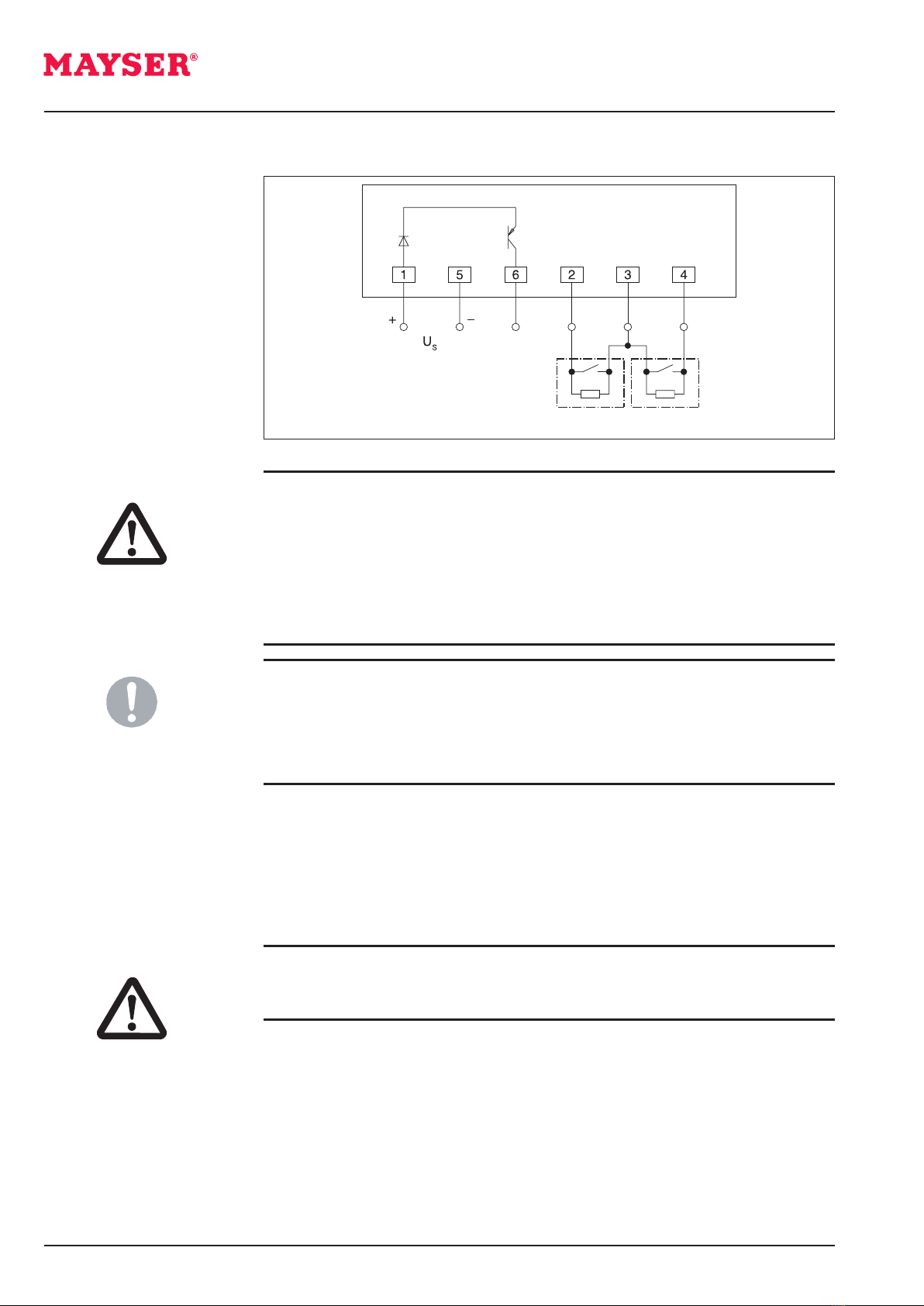
Connections..............................................................................................................................................................................6
Function, installation and commissioning............................................................................................................... 6
Function.....................................................................................................................................................................................6
Installation................................................................................................................................................................................7
Commissioning........................................................................................................................................................................8
Testing the function...................................................................................................................................................8
Recommissioning................................................................................................................................................................. 10
Automatic reset........................................................................................................................................................ 10
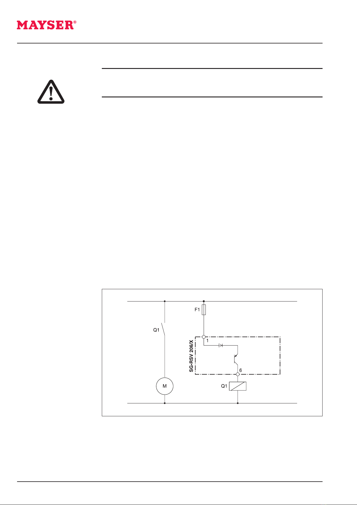
Connection example........................................................................................................................................................... 10
Maintenance and cleaning ....................................................................................................................................... 11
Maintenance ......................................................................................................................................................................... 11
Cleaning.................................................................................................................................................................................. 11
Troubleshooting and remedies................................................................................................................................ 11
Replacement parts .............................................................................................................................................................. 13
Disposal ........................................................................................................................................................................ 13
Technical data.............................................................................................................................................................. 14

170912 v3.1cd Operating instructions SG-RSV 206/X Page3/14
About these operating instructions
These operating instructions are part of the product.
Mayser Polymer Electric accepts no responsibility or warranty claims for damage and
consequential damage due to failure to observe the operating instructions.
ÄRead the operating instructions carefully before use.
ÄKeep the operating instructions somewhere safe so you can refer to them
throughout the product’s entire service life.
ÄPass the operating instructions on to every subsequent owner or user of the
product.
ÄAdd any supplement received from the manufacturer to the operating instruc-
tions.
These operating instructions are only valid for the products specified on the title
page.
Validity
The target group of these operating instructions are operators and trained specialist
personnel who are familiar with installation and commissioning.
Target group
ÄIn addition to the operating instructions, observe the following documents:
- Drawing of the sensor system (optional)
- Wiring diagram (optional)
- Installation instructions for the sensors used
Other applicable
documents
Symbol Meaning
Ä... Action with one step or with more than one step where
the order is not relevant.
1. ...
2. ...
3. ...
Action with more than one step where the order is rel-
evant.
• ...
- ...
Bullets first level
Bullets second level
(see Installation) Cross-reference
Symbols used

Page 4/14 Operating instructions SG-RSV 206/X 170912 v3.1cd
ÄDo not interconnect control units
Do not combine control units by interconnecting them.
Safety instructions
ÄDo not open control unit
Never open, tamper with or alter the control unit.
ÄCheck supply voltage
Check the supply voltage. It must correspond to the connecting voltage USspeci-
fied on the type plate.
ÄEnsure sucient clearance
When installing the product in a switch cabinet, ensure sucient clearance from
heat sources (at least 2cm).
Intended use
The control unit conforms to ISO13849-1:2006 category 1 PL c. To prevent any re-
duction in the safety classification, the downstream control must be of the same cat-
egory or higher.
The control unit is designed for processing the signals of a pressure-sensitive protec-
tion device (PSPD). It evaluates the output signals of sensors with a 1k2 monitoring
resistor. The integrated output signal switching devices (OSSD) transmit the evaluat-
ed safety signals directly to the downstream machine controls.
ÄObserve correct terminal assignment
Observe the correct terminal assignment when connecting the supply voltage.
Terminals 2, 3 and 4 are not voltage-free.
Symbol Meaning
DANGER Immediate danger leading to death or serious injury.
CAUTION Possible danger which may lead to minor injury or damage
to property.
Information on easier and safer working practices.
Danger symbols and
information

170912 v3.1cd Operating instructions SG-RSV 206/X Page5/14
Parts supplied
1× Control unit
Potted electronics with permanently installed connection wires.
1× Operating Instructions
1× Declaration of Conformity
Upon receipt, immediately check the parts supplied to ensure they are complete and
in good condition.
ÄDo not use in ATEX zones
Do not use the control unit in potentially explosive environments (ATEX). The
control unit is not authorised for use in these zones.
ÄIn the event of a fault, put out of operation
In the event of malfunctions and visible damage, put the control unit out of oper-
ation by decommissioning it.
ÄDo not overload control unit
Ensure that the specified switching current is not exceeded.
ÄStore control units in a dry place inside the original packaging.
ÄObserve the storage temperatures given in the technical data.
Storage
The control units are packed in such a way as to ensure a good level of protection.
Several control units are stacked together in one large cardboard box.
The documents are enclosed separately.
Packaging and transport
Transport and storage

Page 6/14 Operating instructions SG-RSV 206/X 170912 v3.1cd
1
6
5
4
3
2
Product overview
Connections
Function, installation and commissioning
Function
Connections: Terminals:
Supply voltage 1, 5
Output 6, 5
Sensor 1 2, 3
Sensor 2 4, 3
The control unit has two monitoring circuits, which operate one output circuit. The
electronics monitor the electrical resistance of the sensors, which have a defined
closed-circuit current.
The control unit is operated with a voltage of 12 or 24VDC. If the supply voltage is
connected, the control unit is ready for operation.
SG-RSV 206/1
Control unit SG-RSV 206/1 has a non-inverted pnp output, which is set to LOW when
the sensors are not activated.
If a sensor is activated or if a cable break occurs on a sensor, the output switches to
HIGH.
SG-RSV 206/2
Control unit SG-RSV 206/2 has an inverted pnp output, which is set to HIGH when
the sensors are not activated.
If a sensor is activated or if a cable break occurs on a sensor, the output switches to
LOW.
Blue
Orange
Green
Red
Yellow
Brown

170912 v3.1cd Operating instructions SG-RSV 206/X Page7/14
4.2
1
2
3
4
5
6
SG-RSV 206/X
Installation
DANGER Danger of injury from electric shock!
ÄDisconnect all devices and live parts in the immediate environment from the
power supply and secure them to prevent them from being switched on again
(see relevant operating instructions).
ÄCheck whether all devices and parts are de-energised.
CAUTION Impaired operation due to overheating
If the control unit overheats, operation of the protection device may be impaired.
ÄWhen installing the product in a switch cabinet, ensure sucient clearance
from heat sources (at least 2cm).
1. Fix the control unit in any position with Ø 4mm screws or secure it using cable
ties.
2. Mount the control unit
- on a level installation surface
- with the rear side and type plate pointing towards the assembly surface. The
raised lettering must not face the assembly surface; otherwise, it will result in
a bending moment.
CAUTION Impaired operation due to mechanical loads
Incorrect installation can generate a bending moment. The bending moment can
impair operation of the protection device.
ÄAvoid any kind of bending moment.

Page 8/14 Operating instructions SG-RSV 206/X 170912 v3.1cd
Testing the function
Commissioning
1. Make sure no sensors are activated.
- Output is set to LOW
Danger of injury from electric shock!
ÄNever disconnect terminals while live.
DANGER
CAUTION Overall safety endangered
Overall safety is aected by the quality and reliability of the interface between the
protection device and the machine.
ÄTake particular care when setting up the interface.
ÄIn the case of screw terminals, only use non-tin-plated conductor cores with
wire end ferrules.
Operation with only one monitoring circuit
It is also possible to operate the control unit with only one monitoring circuit.
ÄTo do this, use a 1k2 resistor to bridge the monitoring circuit that is not re-
quired.
Sensor 1
Output
Sensor 2
2. Wire the sensors, relay contacts and supply voltage to the cable terminals.
ÄConnect the supply voltage.
Control unit RSV 206/1

170912 v3.1cd Operating instructions SG-RSV 206/X Page9/14
1. Make sure no sensors are activated.
- Output is set to HIGH
2. Activate sensor 1.
- Output is set to LOW
3. Repeat step 1.
4. Activate sensor 2.
- Output is set to LOW
5. Repeat step 1.
6. Disconnect sensor 1.
- Output is set to LOW
7. Repeat step 1.
8. Disconnect sensor 2.
- Output is set to LOW
9. Repeat step 1.
Control unit RSV 206/2
2. Activate sensor 1.
- Output is set to HIGH
3. Repeat step 1.
4. Activate sensor 2.
- Output is set to HIGH
5. Repeat step 1.
6. Disconnect sensor 1.
- Output is set to HIGH
7. Repeat step 1.
8. Disconnect sensor 2.
- Output is set to HIGH
9. Repeat step 1.

Page 10/14 Operating instructions SG-RSV 206/X 170912 v3.1cd
Connection example
Danger of injury!
ÄNever start your machine as long as the danger remains.
DANGER
Recommissioning
The control unit works without a reset. If the sensor is released after activation, the
output returns to “HIGH” after a delay tw.
The control unit works without a reset. If the sensor is released after activation, the
output returns to “LOW” after a delay tw.
ÄAfter recommissioning, check the unit for proper functioning (see section Com-
missioning).
Automatic reset
Control unit RSV 206/1
Control unit RSV 206/2

170912 v3.1cd Operating instructions SG-RSV 206/X Page11/14
Maintenance and cleaning
Maintenance
Cleaning
The control unit is maintenance-free.
ÄRepeat the functional test monthly.
ÄClean the outside of the enclosure with a dry cloth.
Danger of injury from electric shock!
ÄDisconnect the control unit – as well as all devices and live parts in the imme-
diate environment – from the power supply and secure them to prevent them
from being switched on again (see relevant operating instructions).
ÄCheck whether all devices and parts are de-energised.
DANGER
Troubleshooting and remedies
Error state Possible cause Remedy
Output remains set to
LOW when the state
changes
No or incorrect supply voltage 1. Check supply voltage, compare with
type plate
2. Check terminal assignment
Output is set to HIGH Incorrect monitoring resistor in sensor
1 or 2, or sensor short circuit
1. Check non-activated sensor;
resistance = 1k2 ±5%
2. Measured resistance deviates signifi-
cantly
ÄReplace sensor
Cable break 1. Check activated sensor; resistance
< 400ohms
2. Measured resistance deviates signifi-
cantly
ÄReplace sensor
If supply voltage is correctly connected and
sensor is OK: control unit is faulty
ÄReplace control unit
Pre-requisites: the control unit is connected to the supply voltage and sensors; the
sensors are not activated.
Control unit RSV 206/1
Still unable to remedy the fault?
ÄContact Mayser-Support: Tel. +49 731 2061-0.

Page 12/14 Operating instructions SG-RSV 206/X 170912 v3.1cd
Still unable to remedy the fault?
ÄContact Mayser-Support: Tel. +49 731 2061-0.
Error state Possible cause Remedy
Output is set to LOW No or incorrect supply voltage 1. Check supply voltage, compare with
type plate
2. Check terminal assignment
Incorrect monitoring resistor in sensor
1 or 2
1. Check non-activated sensor;
resistance = 1k2 ±5%
2. Measured resistance deviates signifi-
cantly
ÄReplace sensor
Cable break 1. Check activated sensor; resistance
< 400ohms
2. Measured resistance deviates signifi-
cantly
ÄReplace sensor
Sensor short circuit 1. Check non-activated sensor;
resistance = 1k2 ±5%
2. Measured resistance deviates signifi-
cantly
ÄReplace sensor
Control unit faulty ÄReplace control unit
Control unit RSV 206/2
Pre-requisites: the control unit is connected to the supply voltage and sensors; the
sensors are not activated.

170912 v3.1cd Operating instructions SG-RSV 206/X Page13/14
Replacement parts
Overall safety endangered
If the sensor and control unit are not replaced using original parts from Mayser, op-
eration of the protection device may be impaired.
ÄOnly use original parts from Mayser.
CAUTION
Disposal
The control units produced by Mayser are professional electronic tools exclusively in-
tended for commercial use (known as B2B devices). Unlike the B2C (business-to-con-
sumer)devices mainly used in private households, they must not be disposed of at
the collection centres of public waste management organisations (e.g. municipal
recycling depots). At the end of their useful life, the devices may be returned to us for
disposal.
WEEE reg. no. DE 39141253

Page 14/14 Operating instructions SG-RSV 206/X 170912 v3.1cd
Technical data
SG-RSV 206/1 SG-RSV 206/2
Testing basis ISO13849-1, 72/245/EEC
Connecting voltage US8 to 32VDC 8 to 32VDC
Voltage tolerance
Nominal current
Nominal frequency
External fuse protection
Power consumption
–
5 to 16mA
–
100mA time-lag
< 1.0W (without load)
–
6 to 24mA
–
100mA time-lag
< 1.0W (without load)
Times
Reaction time ta
Restart time tw
< 1ms
< 1ms
< 1ms
< 1ms
Safety classifications
EN1760: Reset function
ISO13849-1:2006
MTTFd
DCavg
nop (assumption)
CCF
Without
Category 1 PL c
860 years
–
52,560 per year
–
Without
Category 1 PL c
801 years
–
52,560 per year
–
Control unit inputs
Sensors 1 and 2
Monitoring resistor
Short-circuit resistance
Line resistance
Line length (max.)
Switching thresholds
Sensor activated
Cable break
Y1, Y2 and Y3, Y4
1k2ohms
≤ 400ohms
≤ 100ohms
100m
< 650ohms
> 3.2kiloohms
Y1, Y2 and Y3, Y4
1k2ohms
≤ 400ohms
≤ 100ohms
100m
< 650ohms
> 3.2kiloohms
Control unit outputs
Output (PNP)
HIGH (min.)
LOW (max.) with
RL≤ 100kiloohms
Switching current (max.)
1, 6
Non-inverted
US– 1.0V
0.5V
50mA
1, 6
Inverted
US– 1.0V
0.5V
50mA
Mechanical operating conditions
Flat ribbon cables
IEC 60529: degree of protection
Max. humidity (23 °C)
Operating temperature
Storage temperature
Vibration fatigue limit
Dimensions (W × H × D)
Weight
6 × 0.22mm2
IP67
85%, non-condensing
−30 to +80°C
−30 to +80°C
1g in all 3 levels
38 × 28 × 7mm
15g
6 × 0.22mm2
IP67
85%, non-condensing
−30 to +80°C
−30 to +80°C
1g in all 3 levels
38 × 28 × 7mm
15g
This manual suits for next models
2
Table of contents
Other MAYSER Cables And Connectors manuals
Popular Cables And Connectors manuals by other brands

Energenie
Energenie ENER017 manual

Monoprice
Monoprice Blackbird HDBaseT 31058 user manual

Simon
Simon 10000561-039 Installation

Spirax Sarco
Spirax Sarco STS17.2 Installation and maintenance instructions

Amphenol
Amphenol Temposonics DT Connector System installation manual

Conrad
Conrad 1278722 operating instructions