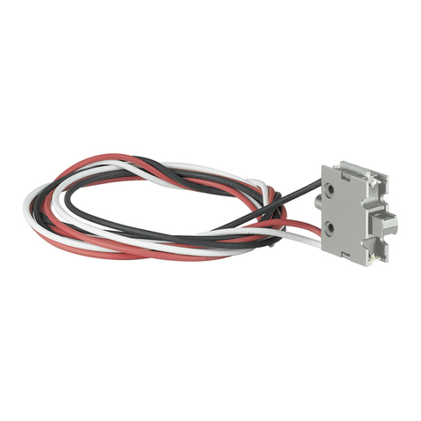
FIELD WIREABLE Q CONNECTORS
For full installation instructions for the Enphase IQ Series Microinverters,
read and follow all warnings and instructions in this guide and in the
Enphase IQ Series Microinverter Installation and Operation Manual at:
enphase.com/support.
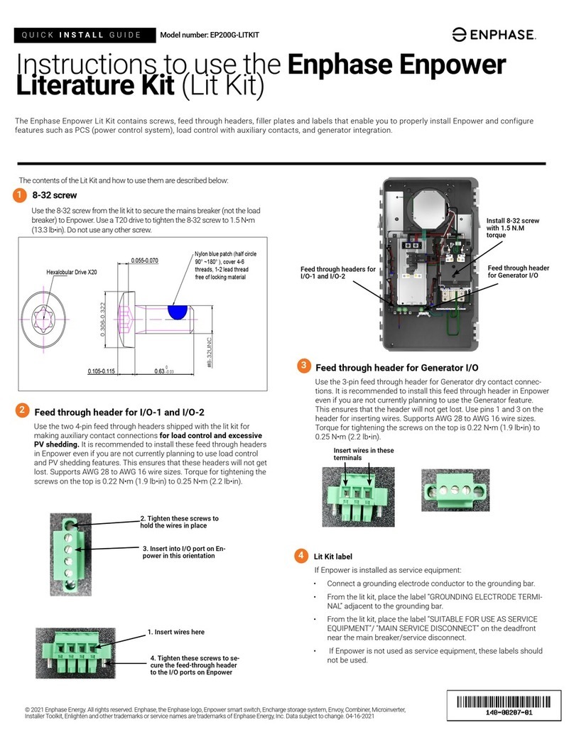
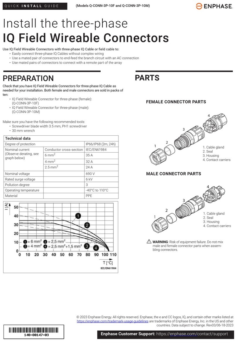
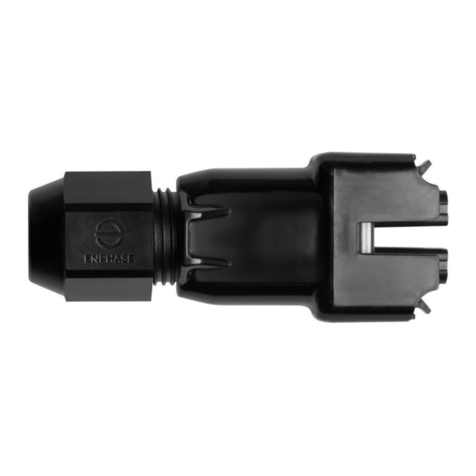
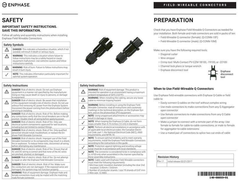
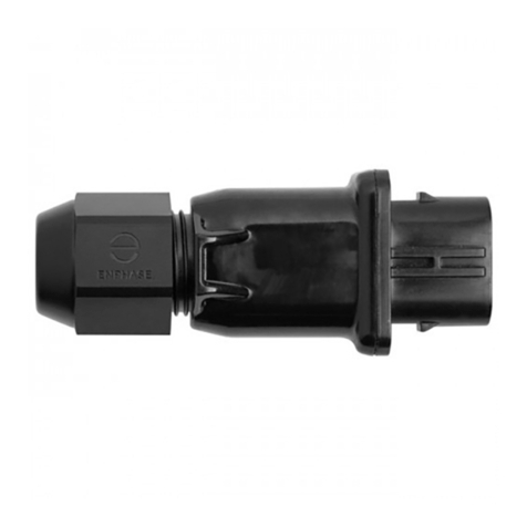
Check that you have Enphase Field Wireable Q Connectors as needed for
your installation. Both female and male connectors are sold in packs of ten:
• Field Wireable Q connector (female): (Q-CONN-10F)
• Field Wireable Q connector (male): (Q-CONN-10M)
Make sure you have the following recommended tools:
• Diagonal cutter
• Wire stripper
• Crimp tool: Multi-Contact PV-CZM-18100, -19100, or -22100
• Torque wrench
• Enphase disconnect tool
When to Use Field Wireable Q Connectors
Use Enphase Field Wireable Q Connectors with Enphase Q Cable or eld
cable to:
• Easily connect Q cables on the roof without complex wiring
• Use male connectors to make connections from a Field Wireable
female connector
• Use female connectors to make connections from any Q Cable
open connector
• Make a jumper to connect with a remote part of the array: Use
female to female for cable-to-cable connections
• Use a mated pair of connectors to splice two cut ends of cable
PREPARATION
Enphase
disconnect
tool
Safety Instructions
+DANGER: Risk of electric shock. Do not use Enphase
equipment in a manner not specied by the manufacturer.
Doing so may cause death or injury to persons, or damage
to equipment.
+DANGER: Risk of electric shock. Be aware that installation
of this equipment includes risk of electric shock. Do not use
without rst removing AC power from the Enphase System.
Disconnect the power coming from the photovoltaics
before servicing or installing.
+DANGER: Risk of electric shock. Risk of re. Before making
any connections verify that the circuit breakers are in the off
position. Double check all wiring before applying power.
+DANGER: Risk of electric shock. Risk of re. Only use
electrical system components approved for wet locations,
including but not limited to conduit ttings.
+DANGER: Risk of electric shock. Risk of re. Only qualied
personnel should install, troubleshoot, or replace the
Enphase Field Wireable Q Connector.
+DANGER: Risk of electric shock. Improper use of the Field
Wireable Q Connector or its components may result in a
shock, re or explosion. To reduce these risks, disconnect
all wiring before attempting any maintenance.
+DANGER: Risk of electric shock. Risk of re. Ensure that all
AC and DC wiring is correct and that none of the AC wires
are pinched, shorted, or damaged.
+DANGER: Risk of electric shock. Risk of re. Do not attempt
to repair or alter the Enphase Field Wireable Q Connector.
+DANGER: Risk of electric shock. Risk of re. Make sure
the conductors are not damaged. If the exposed wires are
damaged, the system may not function properly.
*WARNING: Risk of equipment damage. Enphase male and
female connectors must only be mated with the matching
male/female connector.
Safety Symbols
+DANGER: This indicates a hazardous situation, which if not
avoided, will result in death or serious injury.
*WARNING: This indicates a situation where failure to
follow instructions may be a safety hazard or cause
equipment malfunction. Use extreme caution and follow
instructions carefully.
;WARNING: Risk of burn. Failure to follow instructions may
result in burn injury.
✓NOTE: This indicates information particularly important for
optimal system operation.
SAFETY
IMPORTANT SAFETY INSTRUCTIONS.
SAVE THIS INFORMATION.
Follow all safety and assembly instructions when installing
Enphase Field Wireable Q Connectors.
Safety Instructions
*WARNING: Risk of equipment damage. This product is
intended for operation in an environment having a maximum
ambient temperature of 55ºC (131ºF).
*WARNING: When installing the cabling, secure any loose
cable to minimize tripping hazard
*WARNING: Before installing or using the Enphase Field
Wireable Q Connector, read all instructions and cautionary
markings in the technical description, on the Enphase
System, and on the photovoltaic (PV) equipment.
✓NOTE: Using unapproved attachments or accessories may
result in damage or injury.
✓NOTE: When looping the Enphase Q Cable, do not form
loops smaller than 4.75 inches (12 cm) in diameter.
✓NOTE: Perform all electrical installations in accordance with
all applicable local electrical codes: the Canadian Electrical
Code, part 1; the National Electrical Code (NEC); ANSI
requirements; and NFPA 70.
✓NOTE: To ensure optimal reliability and to meet warranty
requirements, install the Enphase Field Wireable Q Connec-
tors according to the instructions in this guide.
✓NOTE: Protection against lightning and resulting voltage
surge must be in accordance with local standards.
✓NOTE: The connector is considered to be in compliance
with UL 6703 only when assembled in the manner specied
by these assembly instructions.
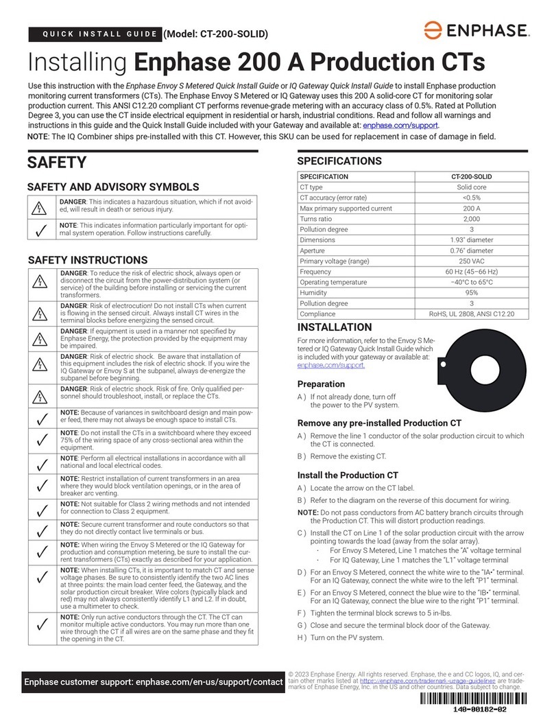
✓NOTE: Cable used with Enphase Field Wireable Q Connec-
tors must meet the following requirements:
• Min/max outer insulation diameter (including the clear 2nd
insulator): 3.45mm / 3.65mm
• Number of conductor strands/size: 19 strands of 0.47 mm
• Wire size: 12 AWG
Revision History
Rev 01 Initial release 02/21/2017.
Rev 02 Revised jacket strip length in step C - 04/10/2017.
Rev 03 Changed tools and updated nut diameter references and
images. 10/03/2017
Rev 04 Removed reference to discontinued product (BA) 05/15/2018
