Maytag Services MDE5500A Series User manual

September 2006 1 16027056
©2006 Maytag Services
Maytag LED Electric Dryer
27" Domestic Dryer⎯⎯
⎯⎯
⎯Technical Information
MDE5500A*, MDE6800A*
•Due to possibility of personal injury or property damage, always contact an authorized technician for servicing or
repair of this unit.
•RefertoServiceManual16023110fordetailedinstallation,operating,testing,troubleshooting,anddisassembly
instructions.
CAUTION
!
AllsafetyinformationmustbefollowedasprovidedinServiceManual16023110.
!WARNING
To avoid risk of electrical shock, personal injury or death; disconnect power to dryer before servicing, unless
testingrequirespower.

16027056 2 September 2006
©2006 Maytag Services
Troubleshooting Procedures
!WARNING
To avoid risk of electrical shock, personal injury or death; disconnect power to dryer before servicing, unless
testingrequirespower.
g
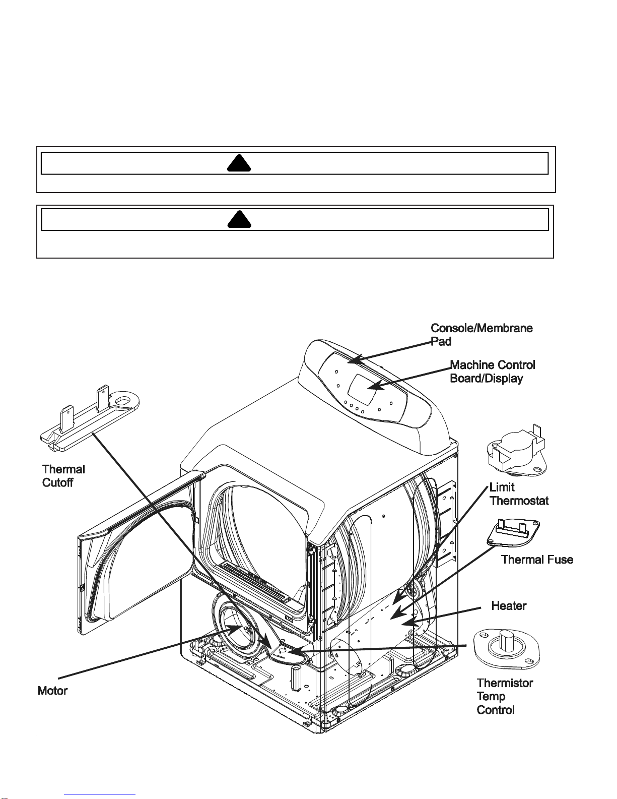
Maytag Dryer MDE6800A, MDE5500B
•Due to possibility of personal injury or property damage, always contact an authorized technician for servicing
or repair of this unit.
Will Not Run
Will not start or run:
• All wires are hooked up to their corresponding
terminals.
• Dryer is plugged in.
• Blown fuse or circuit breaker.
• Door switch functional...door closed.
• Start/Pause switch functional.
• Control Board operational.
• Drive motor functional.
• Blown thermal fuse.
Motor runs/ tumbler will not turn:
• Belt off or broken/damaged.
• Idler tension spring too weak or stretched.
• Idler pulley jammed or stuck.
Runs a few minutes and then stops:
• Lint buildup around drive motor.
• Low voltage present.
• Blower impeller blocked in blower
housing.
• Drive motor - start switch contacts stuck closed.
Blows fuses or trips circuit breaker:
• The amperage readings are at 240 volts. One line
will be 24 amps and the other line will be 21 amps.
The neutral line will be at 3 amps. If the above
amperages are present, then the house wiring,
fuse box or circuit breaker should be suspect.
• Shorted heating element to housing.
• Incorrect wiring or a wire shorting to ground.
• Drive motor winding shorting to ground.
Will Not Dry
Will not heat (motor runs):
• Open heating element.
• Hi-Limit trips easily or is open.
• Regulating thermostat trips easily or is open.
• Membrane switch open.
• Drive motor centrifugal start switch not allowing
voltage to gas valve or heating element.
Improper drying/clothes wrinkled/ rough
texture/long dry time:
• Lint filter is not clean.
• Restriction in exhaust.
• Outside exhaust hood damper door stuck closed.
• Exhaust too long, too many elbows, flex ductwork
installed.
• Poor makeup air available for the dryer.
• Incorrect tumbler speed. Tumbler belt slipping.
• Blower impeller bound; check for foreign material
in blower area.
• Customer overloading dryer.
• Check clothing labels for fabric content and cycle
selected.
• Clothes too wet due to insufficient spin out by
washer.
Will Not Shut Off
Short in Sensor Circuit.
Check Membrane Pad.
Check Electronic Control Board.
Troubleshooting the electronic
control circuit:
• Check for miswiring of the electrical connector at
the electronic control board.
• Does not shut off, then the problem is in the
electronic control unit. Disconnect the sensor wire
from the sensor bar. If the dryer runs for about 20
minutes, then shuts down or the timer advances,
then the electronic control unit is good and the
problem lies in the sensor bar.
• Check sensor for continuity. If found, replace
sensor bar or clean with alcohol. Some fabric
softener sheets will coat the sensor bars.
Noisy and/Or Vibration
• Thumping Check for loose tumbler baffle, rear
tumbler roller(s) worn or misaligned, out-of-round
tumbler or high weld seam on tumbler.
• Ticking Check for loose wire harness or object
caught in blower wheel area.
• Scraping Check for front or rear bulkhead felt seal
out of position or worn tumbler front bearings.
• Roaring Check for blower wheel rubbing on blower
housing or bad motor bearings.
• Popping or squealing sound.Check for a sticky
or frayed belt.
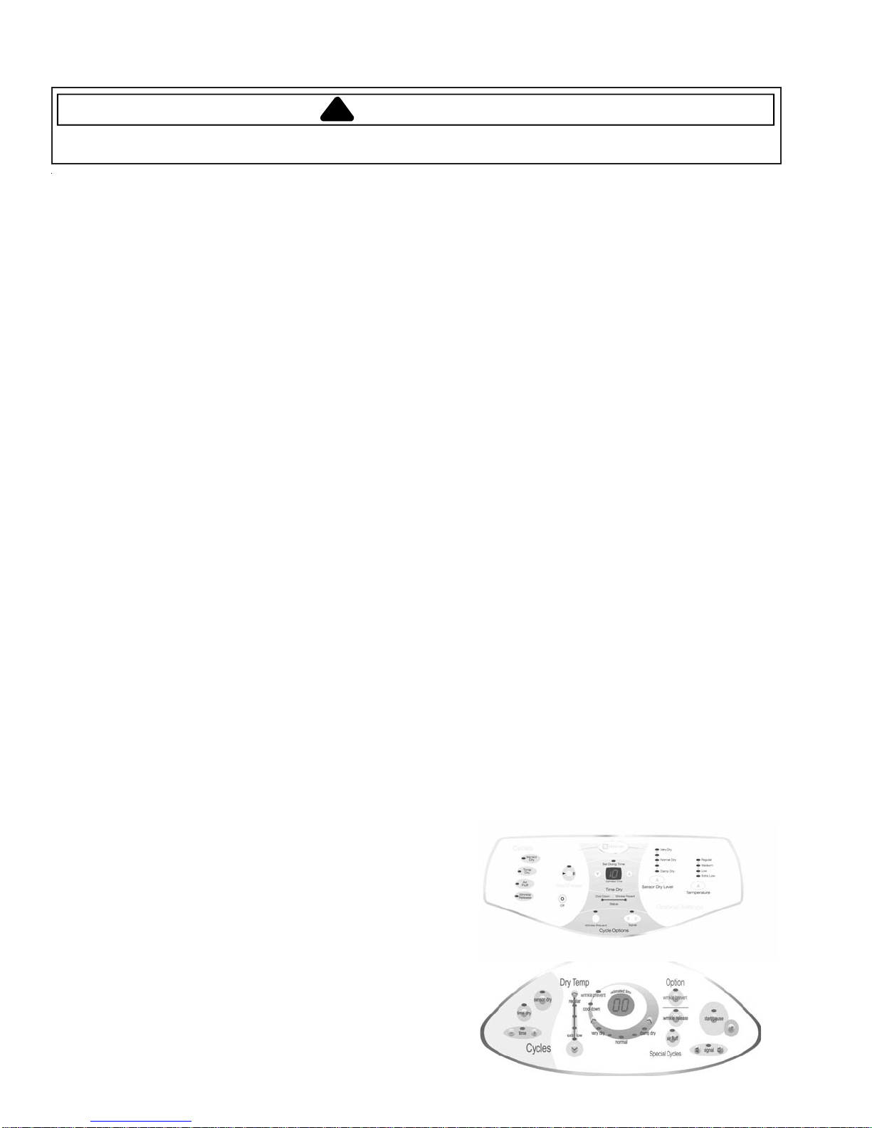
Control Configuration
This Trouble Shooting guide illustrates how the
software works with the 13 and 15 key membrane
switches. The section on Accessing Diagnostic Codes
includes instruction for use with older control boards.
13 Key Membrane
15 Key Membrane

September 2006 3 16027056
©2006 Maytag Services
!WARNING
To avoid risk of electrical shock, personal injury or death; disconnect power to dryer before servicing, unless
testingrequirespower.
Troubleshooting Procedures
Service Mode
This mode provides Service Personnel the ability to
verify the operation of the dryer.
The Service Mode can be implemented in the middle of
any dry cycle. While in the Service Mode, the
Technician can start special diagnostic tests such as a
System Check Mode, Membrane Pad Check, Display
Software version number and display diagnostic/help
code listings.
Enter Service Mode:
Press Air Fluff and Time (^) - 13 Key Membrane.
or
Air Fluff and Time (+) - 15 KeyMembrane.
keys for 3 seconds, or until a beep is heard. The
machine will now be in Service Mode and “d” will be
displayed.
Exit Service Mode
Press the OFF key to exit Service Mode or repeat the
Air Fluff and Time (+) sequence.
Diagnostic Tests
The following table lists the various tests available while
in the Service Mode, which can be accessed by
pressing the following keys:
Key Press Special
Test/Function
Wrinkle release
Then press
Temperature (^) - 13 Key
or
Dry Temp (^) - 15 Key
Display list of
diagnostic codes.
To sequence thru
the diagnostic
and help codes.
Time (v) - 13 Key
or
Time (-) - 15 Key
Display revision
number
Sensor Dry Level (^) - 13
Key
or
Very Dry (<) - 15 Key
View current
cycle temperature
in Celsius
Start/Pause Start or pause
cycle running but
remain in
diagnostic mode.
System Check Mode
While in Service Mode, pressing the
Air Fluff and Signal (+) - 13 Key Membrane
or
Air Fluff and Signal (+) - 15 Key Membrane
keys for 3 seconds, will put the dryer into the System
Check mode and "SC" will display. The following table
lists the various functions based on the keys being
pressed.
System Check Mode Table
Membrane Pad Check
The membrane check turns all the embedded LED’s on.
All the LED’s can then be toggled off by pressing the
key associated with the LED.
While in System Check Mode, pressing the
Air Fluff and Sensor Dry - 13 Key
or
Air Fluff and Sensor Dry - 15 Key
keys for 2 seconds, will start a Membrane Pad Switch
Test. To exit the test at any point, press the same keys
again for 2 seconds or press the OFF key to exit
Service Mode.
Key Pressed: Function
Performed
Sensor Dry Enable sensor
dry circuit (sense
dry LED) when
short circuit is
detected across
the sensor bars
the normal dry
LED will turn on.
Start/Pause Cycles the motor
relay on/off.
When the motor
is running the
start/pause LED
is on.
Temperature (^) - 13 Key
or
Dry Temp (^) - 15 Key
If motor is
running, cycles
the heater/gas
valve on/off.
When the heater
is regular temp
LED is on.
Sensor Dry Level (^) - 13
Key
or
Very Dry (<) - 15 Key
View current
cycle temperature
in Celsius.

16027056 4 September 2006
©2006 Maytag Services
!WARNING
To avoid risk of electrical shock, personal injury or death; disconnect power to dryer before servicing, unless
testingrequirespower.
Troubleshooting Procedures
Diagnostic Codes
The Diagnostic Codes are identified when the severity
level of the abnormality detected is higher and service
may be required.
When a problem with the dryer is detected a Diagnostic
Code is assigned, and can be displayed. The Control
Board will not log multiple same codes per cycle;
however, it will log as many Diagnostics as possible for
the machine to continue running.
Accessing Diagnostic Codes with 13 Key Membrane
Press Air Fluff and Time (^) to enter Service Mode.
Press the Wrinkle Release key to access the
Diagnostic Codes. Scroll through the Diagnostic Codes
by pressing the Temperature (^) key. The first time the
key is pressed the newest code will be displayed. Each
additional key press shows the next code. Once all the
codes have been displayed a “d” is displayed and the
process repeats. If there are no Diagnostic Codes
available, “00” will be displayed for the Diagnostic Code.
Accessing Diagnostic Codes with 15 Key Membrane
Press Air Fluff and Time (+) to enter Service Mode.
Press the Wrinkle Release key to access the
Diagnostic Codes. Scroll through the Diagnostic Codes
by pressing the Temperature (^). The first time the key
is pressed the newest code will be displayed. Each
additional key press shows the next code. Once all the
codes have been displayed a “d” is displayed and the
process repeats. If there are no Diagnostic Codes
available, “00” will be displayed for the Diagnostic Code.
There will be no multiple occurrences of either a
diagnostic code or help code generated in the same
cycle reported on the list. But if the same code occurs in
repeated cycles, it will be registered.
Clearing Diagnostic Codes
To clear the diagnostic code list press
Air Fluff and Wrinkle Release - 13 Key
or
Air Fluff and Wrinkle Release - 15 Key
for 3 seconds while in diagnostic mode.
Diagnostic Codes
Code Description Trigger Action Taken
1 Dryer Thermistor
Short Sensed The
thermistor
resistance is
very low,
with a
temperature
> 175 ºF.
Check for:
-Clogged lint
screen.
-Restricted
vent system.
Failed thermistor.
Code Description Trigger Action Taken
2 Thermistor Open
Sensed The
thermistor
resistance is
very high
Check for:
-Low ambient
temperature in
room (Below
50ºF/10ºC).
-Outside vent
damper is stuck
open in
wintertime.
Loose or open wire
terminals
3 Door Circuit
Failure Invalid state
for more
than 256
milliseconds
Check for:
- Loose or open wire
terminals in Door
Sense circuit.
4 Possible motor
transistor error If either
motor
transistor is
seen open or
shorted
during
startup
Check for:
-Loose
connections in
motor circuit.
-Run System
Check Mode
and check the
motor relay
function.
-If relay
functions,
disregard the
diagnostic
code.
If relay does not
function, replace
machine control
board.
5 Not Used
6 Non Volatile
Memory Problem
Detected
with integrity
of
parameters
stored in
EEPROM
memory.
Disregard
8 Stuck Key A key is
sensed to be
pressed
more than
75 seconds,
the key shall
be assumed
to be stuck.
Run membrane pad
check and replace
console w/membrane
pad if necessary.

September 2006 5 16027056
©2006 Maytag Services
!WARNING
To avoid risk of electrical shock, personal injury or death; disconnect power to dryer before servicing, unless
testingrequirespower.
Troubleshooting Procedures
J7 Connector Ribbon
Harness
Pin No. 1
Membrane Pad Continuity Checks
Note: Unplug connector and touch probe of meter to the
appropriate pin numbers. Meter will show infinity on
open keys and continuity on closed keys.
Membrane
Pad Pin Number Pin Number
Sensor dry J7(12) J7(13)
Time dry J7(11) J7(13)
Time(^) 13 Key
Time(+) 15 Key
J7(10) J7(13)
Time(v) 13 Key
Time(-) 15 Key
J7(9) J7(13)
Temperature (^) 13 Key
Dry Temp(^) 15 Key
J7(11) J7(14)
Dry Temp (v) 15 Key J7(10) J7(14)
Sensor Dry Level 13
Key
Very Dry (<) 15 Key
J7(12) J7(14)
Damp Dry (>) 15 Key J7(19) J7(14)
Wrinkle Release J7(11) J7(15)
Wrinkle Prevent J7(9) J7(15)
Air Fluff J7(10) J7(15)
Start/Pause J7(11) J7(16)
Signal(v) 13 Key
Signal(-) 15 Key
J7(12) J7(15)
Off J7(9) J7(16)
Signal(^) 13 Key
Signal(+) 15 Key
J7(12) J7(16)
Description Connector
Pin Num
Connector
Pin Num
Voltage Comments
Heater Relay Internal
Output
P1 BB1(1) 120VAC
LI Board (input) BB1(1) BB2(3) 120VAC Door must be closed.
Motor
(input)
BB1(2) BB2(3) 120VAC Door must be closed
Neutral (input) BB2(2) BB1(1) 120VAC
Door Sense BB2(3) BB1(1) 120VAC Door must be open
Thermistor J4(1) J4(2) 5VDC NTC
70 F = 10K ohms
150 F = 1754 ohms
Sensor Bar J4(3) J4(4) 24VDC
P1
BB1 BB2 J4
J3

16027056 6 September 2006
©2006 Maytag Services
!WARNING
To avoid risk of electrical shock, personal injury or death; disconnect power to dryer before servicing, unless
testingrequirespower.
Wiring Schematics
Series 10 - 36

September 2006 7 16027056
©2006 Maytag Services
!WARNING
To avoid risk of electrical shock, personal injury or death; disconnect power to dryer before servicing, unless
testingrequirespower.
Wiring Schematics
Series 37, 66
63901290

16027056 8 September 2006
©2006 Maytag Services
Series 67 to current
!WARNING
To avoid risk of electrical shock, personal injury or death; disconnect power to dryer before servicing, unless
testingrequirespower.
Wiring Schematics
This manual suits for next models
1
Table of contents
Other Maytag Services Dryer manuals