manuals.online logo
Brands
  1. Home
  2. •
  3. Brands
  4. •
  5. Maytag
  6. •
  7. Dryer
  8. •
  9. Maytag 53-3442 User manual

Maytag 53-3442 User manual

'h'1,
PLEASE READ ALL INSTALLATION
INSTRUCTIONS AND REQUIREMENTS
BEFORE INSTALLING
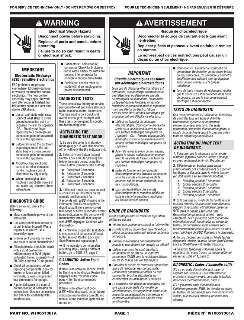
ELECTRIC
WARNING
OR'IOURSAFETY
Do notstore or use gasoline or other
flammable vapors or liquids in the
vicinity of this or any other appliance.
• %
3/8"DEEPWELL DRIVER CHANNEL LOCK PLIERS SCREWDRIVER PUTTY KNIFE DUCT TAPE
1/,,-DRIVEROR ADJUSTABLE WRENCH (BLADE & TORX)
INSTALLINGYOUR NEW DRYER BACKGUARD
/
FORYOURSAFETYANDTHEPROPEROPERA- //
/
TION OFYOUR NEW DRYER,THE DRYER
MUSTBE INSTALLEDIN ACCORDANCEWITH 1\ \\
ALLTHEINSTALLATIONREQUIREMENTS.
Allliteratureshouldberemovedfrominsidedryerand -
savedforfuturereference. ["
NOTE:DO NOTRAISEOR LOWERTHEDRYERBY
THEBACKGUARD.
1. Toremovethe corrugatedcratebase,placeyour _-
footonthebasecloseto a levelingfoot.Pushing
downfirmlywithyourfoot,tiltthe dryerawayfrom
you.
2. Repeatprocesswithall levelingfeet (4).Remove _---._. -_ ,
excessbasebyhand.
CORRUGATED CRATE PLACE FOOT
P/N 53-3442 BASE FOR LEVERAGE
1
NSTALLATION REC!UREMENTS
PLEASEREAD All Installation Instructions and Requirements Before Installing Power Cord.
IT IS RECOMMENDED THAT A QUALIRED ELECTRkDryers installed in manufactured (mobile) homes must be
ClAN ORSERVICETECHNICIAN INSTALLYOUR DRYER. connected with 4 conductor type SRD or SRDT cord to a 3
pole, 4 wire grounding type receptacle; by metal-clad cable;
or suitable conductorsenclosed in flexible metal conduit. If
LOCATIONusing metal-clad cable or flexible conduit, leave at least 3
This clothes dryer is designed so that it can be feet free to permit moving the dryer.
installed in most locations in the home. The dryer may
even be installed in an unheated indoor location,such Where permitted by local codes, a flexible power cord (pig-
as a utility room or building. However, with models hav- tail) may be connected to the dryer. A receptacle should be
ing automatic dry cycles, the TIME DRY SETTING installed in a separate circuit connected tothe main service
SHOULD BE USED WHEN THE ROOM TEMPERA- entrance panel for this type of installation. See Figure #3.
TURE DROPS BELOW 50 DEGREES FAHRENHEIT Use onlya 3 or 4 wire power cord kit,includingstrainrelief,
OR (10 DEGREES C.), AS THE AUTOMATIC CYCLE listed byU.L.foruse withdryers.Thepower cordmusthave
MAYNOT SHUT OFF. a ratingof30 amperes, 120/240voltsAC minimumand be
terminatedinclosed looporopenspade lugs withupturned
DO NOT INSTALL THE DRYER ON A CARPETED ends.The attachmentplugofthe powercordandtherecep-
FLOOR. tacleto whichit willbeconnectedmusthaveaminimum cur-
DO NOT INSTALLOR STORE THE DRYER WHERE rent rating of30 amps andhave matchingconfigurations.
IT MAY BE EXPOSED TO THE WEATHER OR DRIP-Typical30 ampereconfigurations are illustratedin figure#3.
PING WATER. IF IT IS EVER EXPOSED TO WATER,
HAVE A QUALIFIED TECHNICIAN CHECK IT GROUNDINGINSTRUCTIONS
BEFORE USING.This appliance MUST BECONNECTED TO A GROUNDED
THE INSTALLATION MUST BE MADE WITH ADEQUATE METAL PERMANENTWIRING SYSTEM; oran equipment-
CLEARANCE TO PERMIT SERVICING. groundingconductormust berunwiththe circuitconductors
and connected to the equipment-grounding terminal or lead
Inordinary installations enough air will be available for prop- on the appliance.
er operation of the dryer. However, if the dryer is installed in
a mobile home, a closet or atightly sealed room, provisions CONNECTINGTHEDRYER
should be made for at least 18 square inches ofventilation I I
area.Air openings measuring a minimum 3 in.by 3 in.should I FIG.#1-3 WIRE HOTWIREROUTED
_ABOVE BRASS STRAP
++o++++++0+0++o,,+++,+ I I
Ordinarily, Iouvered doors will satisfy the ventilation require- LINE
ments. Dryers installed in a bedroom, bathroom,or closet (BLACI<
must beexhausted outdoors. I-._..11"-/.CRASSSTRAP/-- STRAIN |
I
ELECTRICAL REQUIREMENTS CLAMP I
ml "'"// [/,_-_._/'/(_._:'-_POWER
This phase of the installation should be done by a qualified NEUTRAl r{l_ll__-_-"-{/// _#//_CORD
service technician or electrician in accordance with the (WRITE _ _.-;___,_
++++++++++°++++d°++I
Aseparate circuit must be provided from themain service
entrance panel (fuse box)to the dryer.The circuit must be a 3
or 4 wire, 120/240 volt, 60 Hz, single phase, AC circuit. Each LINE2
(RED)
ofthe120 volt line wires (line t and2)of this circuitmust be I
protected by 30 ampere time delay fuses or circuit breakers.IWJ 'NEUTRALWIRE
Do not fuse the neutral line or the ground line (if provided). HOTWIREROUTED _--_J ROUTEDBELOW
BELOW BRASS STRAP BRASS STRAP
All wires (including neutral and ground if provided) of the I
dryer circuit must be No. 10 gauge copper wirefor up to 40
ft. lengths and No. 8 gauge copper wire for up to 60 ft.THENATIONALELECTRICAL CODEAND ALL
Lengths.NEVER USE A TWO WIRE CABLE WITH AN LOCAL CODES AND ORDINANCES MUST BE
UNINSULATED GROUND WIRE TO CONNECT THEOBSERVED WHEN CONNECTING THIS DRYER.
DRYER.
The NationalElectric Code requires that a means to discon- 1. To gain access to the terminalblock, remove the supply
nect all ungrounded conductors (line 1 and line 2) to the cord cover plate attached to the rear of the dryer.
dryer beprovided forservice. If a powercord andreceptacle
are provided this requirement is met. If other means are 2. Installa suitable strain relief clamp or connector in the
used a suitable switch or circuit breaker must be installed strain relief hole located adjacent to the terminal block.
withinsight of thedryer. 2
3.Route the power cord (pigtail) or cable conductors through
the strain relief clamp. FIG. #2 - 4 WIRE
TERMINALBLOCK
,_ CAUTION -The conductorsshould notextendintoI
thedryermorethannecessary to makethe electricalJ LINEt
connections.(BLACK) GREEN_/IRE
4.Referto theTypical Electricalconnectionslisted below
and makethe electrical connectionsasinstructed.We
recommendthat aqualifiedservicetechnicianor electri- NEUTRALGROUND
clan beconsultedbeforeconnectingthedryer.(WHITE) SCREW
NOTE: DO NOT REMOVETHE INTERNALGROUNDWlRE
OR BRASS STRAP EXCEPT WHERE INSTRUCTED AND
REQUIRED BY LOCAL CODES AND ORDINANCES OF
YOUR AREA.LINE2
(RED)
5.Check to be certain all conductorsarecorrectlyinstalled.
Thensecurely tighten all terminal nutsandtheground
screw.
6.Tighten thestrain reliefclamp.
7. Replace the supply cord cover plate.FIG.#3 TypicalInstallationWith
Flexible Power Cord (Pigtail)
8. Complete the dryer installation.
White (Neutral)
k
TYPICAL ELECTRICAL CONNECTIONS
3-WIRE SYSTEM WITH GROUNDED NEUTRAL - Black (Line 1) _ Red (Line2)
Connect power cord conductors to the line1, neutral,
and line 2 terminals of the terminal block as shown in 3-wire
Plug - NEMA 10-30P
Figure #1. ReceptacleNEMA10-30R
NOTE: Some 3-wire flat type power cords are notcolor
coded. When using this type of power cord, connect the White(Neutral)
centerconductor to theNeutral, connect one ofthe out-
side conductors to line 1, and connect the other outside
conductor to line 2. Slack(Line1) Red (Line 2)
Green (Ground)
4-Wire
3-WIRESYSTEM WITH GROUNDEDMETALCLAD Plug-NEMA14-30P
CABLE OR RIGID METAL CONDUIT - Remove the ReceptacleNEMA14-30R
internal green ground wire or brass strap from the
Neutral terminal and the ground screw. Connect the
power cable conductors to the line 1, Neutral, and line
2 terminals as shown in Figure #2.
NOTE; Anapproved grounding type strain reliefclamp
or conduit connector must be installed for this type of
installation.
4-WIRE SYSTEM - Remove internal green ground wire
or brass strap fromtheNeutral terminal andtheground
screw.Connect thepower cord greengrounding con-
ductor to the ground screw. Connect theremaining_BEFORE OPERATING YOUR DRYER READ
power cordconductorsto theline1, Neutral,and line2ALL SAFETY PRECAUTIONS LISTEDIN THE
terminalsas shownin Figure#2. OPERATINGINSTRUCTIONS.
3
1.LEVELING 2. STABILITY
/
WITHHANDS
FOOT TO CHECKIF
LEVELAND
STABLE
Setall leveling feet at same height. A Place dryer in the location where it will
minimum of Y2'clearance between the be used. Check, by rocking dryer with
machine and the floor is recommend- hands on opposite corners, that all
ed. Adjust to match the height of your four (4) feet are in firm contact with the
dryer, floor. If it rocks, adjust as needed.
3A.OUTSIDEWALL 3B. BASEMENTWALL 3C.FLOOREXHAUSTING
r BASEMENTWINBOWJ
WALL
_o
SIDEVIEW
OUTSIDEWALL-- '
I Attach dryerventpipeto outside If spacepermits,a 4" dia.elbow point-
exhaust vent.Outside exhaust vented downwardthroughthefloormaybe
shouldfit overdryervent pipetoavoidInbasements, the exhaustcanbe ele-
catching lint.Tapeall jointswithheat vatedby installingelbowsto raisetheused If not possible,thedryermay be
duct tape. vent hood above the ground level, tratedexhaustedlaterthroughinthis manual.thebottom as illus-
3D. INDOOREXHAUSTING 4. ELECTRICALCONNECTION INSTALLATIONWlTH
(NOT RECOMMENDED unless POWERCORD(PIGTAIL).
conditionson page6 aremet.)
POWER CORD
__ ATTACHMENT WALL
DRYER PLUG RECEPTACLE MAINSERVICE
._,_ENTRANCEPANEL
When exhausting indoors, use the This appliance must be connected to agrounded metal, permanentwiring
indoor exhaust kit and maintain a mini- system; or an equipment - grounding conductor must be run with the cir-
mum clearance of 6 inches between the
rear of the dryer and any adjacent wall.cuit conductors and connected to the equipment - grounding terminal or
Read further instructions in this manual, lead on the appliance.
Page 6.
4
EXHAUSTVENTING RECUIREMENTS
VENTHOODTYPE
WARNINIFIRE HAZARD Numberof
90°Turns [_NEVEREXHAUST INTO A CHIMNEY,DUCT, GASSeparatedby --
VENT, WALL, CEILING,ATTIC, CONFINED SPACE, atleast4 ft.
BEDROOM, OR UNDER A BUILDING. ofStraightRun_]OPENING/n4" OPENING_JI_ 2_"
DO NOT USE VINYL, PLASTIC, CLOTH OR OTHER 0 45feet 30feet
NONMETALIC DUCT TOEXHAUSTTHE DRYER.1 35feet 20feet
MULTIPLE INSTALLATIONS REQUIRE INDIVIDUAL 2 25feet 10feet
EXHAUST SYSTEMS. Vent should never exceed 0.6 inches water column back
DRYERS INSTALLED IN A MANUFACTURED pressure, fluff empty dryer.
(MOBILE) HOME MUST BE VENTED OUTDOORS.
PERIODICALLY CLEAN LINT FROMVENT SYSTEM. BOTTOM EXHAUSTING
CLEAN FREQUENTLY IF USINGMAXIMUM If spacepermitsbehindthedryer, a 4"elbowpointeddown-
LENGTH OF VENT.ward may be used topass the exhaust system through the
floor.If this is not possible, the dryer may be exhausted
through the bottom as illustrated in FIG. #7. When exhaust-
Exhausting can be accomplished directly from the rear of ing in this manner, the installationshould be made accord-
the cabinet, through right side of the cabinet, or down- ing to the following steps:
ward through the cabinet base. If your existing ductwork is 1.Disconnect electric cord.
plastic, nonmetal, or combustible, replace it with METAL. 2. Raisethetop of thedryer by pressing in with aputty knife
Standard four inch diameter galvanized or aluminum pipe on the top panel retaining clips. FIG. #5.
should be used. DO NOT use any pipe which may be sus-
ceptible to rustor COMBUSTION.Toavoid catching lint _p
the crimped end of each pipe section should face away FIG. #5_ PROX 4"
from the dryer. Do not use screws or other fasteners that,__.,__, _
extend into the exhaust pipe or duct.
Flexible 4"diameter metal tubing may be used for
exhausting thedryer. However, the convolutions create a
greater restriction than pipe and serious blockage can
result if the tubing is bent too sharply.If clearance to the
wall is less than 8 inches,use a 4" sheet metal elbow at
the rear of the dryer to avoid a sharp bend in the tubing.3. Removefront panel by removing two '/4"screws inside top
Do not use over 8 feet (2.5 m.) of flexible metallic tubing corners of front panel.Disconnect door switch wires.
between the elbow and the vent hood.NOTEposition of front seal before removing front panel.
_---_ 4. Remove the cylinder as follows:
VENTHOOD ////Ill _ - -
The use of a vent hood _[_ _ /-GROOVEDSIDE
ontheoutsideisrecom- _--mended. FIG'#6 _----_ "_'_ OFBELTDOwN
When the dryer stops the damper automatically closes to \_"_ ._S IDLERPULLEY
preventdraftsand the entrance of insects androdents. To FRONTOF _,,,.-"_k\ _/I _ _ MOTOR
avoid restricting the outlet, maintain a minimum 8 inch DRYER P _'_._,/PULLEY
clearancebetween thehoodandthegroundor other
obstruction. GROOVED SIDE /
OF BELTUP
FIG. #4a. Forceidler pulley to the right and remove cylinder belt
PECONNECTION fromidlerand motor pulleys.See FIG.#6.
b. Liftup and turn cylinder to clear the roller supports.
---%c. Lift out of cabinet.
EXHAUSTFLOW EXHAUSTFLOW 5.Remove tape and screwsecuring dryer vent pipe.
6. Removethe4" dryer vent pipeand shorten to a suitable
I length. Length depends on type of elbowpurchased.
CORRECT INCORRECT 7.Remove knockout from dryer base.
LENGTHOFVENT 8. Place dryer in position and mark duct location on floor.
MaximumLengthof4"RigidDuct Checkfloorjoistlocationbeforesawing holeinfloor.
5
9. Saw a 4',_"hole in floor and position dryer. When exhausting from the side, the installation should be
10. Secure the shortened pipe to the blower housing with a made according to the steps described in BOTTOM
screw at thetopand sealall joints with tape or silicone EXHAUSTING and as noted above.
bathtub caulk.
11.Install a 4" 90 degreeelbowas shown. INDOOR EXHAUSTING
Step #3D showsa typicalinstallationwithindoorexhausting.
Indoor exhausting is not recommended unless the laundry
FIG. #7 REPLACESCREW room is large and sufficient cross ventilation is available by
ANDTA_7" 90DEGREEELBOW openingtwo windows, oradoorand awindow,or wherean
L_ }lil_4"DIAl7exhaust fan is located in the laundry room.
/ /I When exhausting indoors, use the Indoor Exhausting Kitand
-- j IL_I_ maintaina minimum clearance of 6 inches between the rear
ofthe dryer and any adjacent wall.The Indoor Exhausting Kit
i1_ VENTPIPE iSavailable from your dealer under Part No.53-0298.
SPECIAL REQUIREMENTS FOR MANUFACTURED
(MOBILE) HOME INSTALLATIONS
12. Seal rear openingofcabinet withthe coverplate provid-
ed with your dryer. Located with literature. Attach cover Followsteps outlined for installation with these exceptions:
plate to rear of the cabinet with #8 sheet metal screws When installed in a manufactured (mobile) home.
or duct tape. (Not supplied) 1.THE DRYER INSTALLATION must conform to the
13. Place cylinder belt around cylinder with grooved side Manufactured Home Construction and Safety,Title 24,
toward cylinder.FIG.#6. HUD (Part 280, 1975).
14.Reinstall cylinder by pushing and turning until rollers are
snapped incylinder grooves and cylinder turns freely. 2.THE DRYER must be attached to the manufactured
15.Position cylinder belt with grooved side around motor (mobile) home structure as follows:
pulley.Pull idler pulley right until smooth side of belt can
be routed around leftsideofidler pulley.FIG.#6. a. Dismantlethedryeras described in bottomexhaust-
16. Rotate cylinder counter-clockwiseto position belt., ing.
17, Replace dryer front and reconnect door switch wires, b.Buytwo #10 1'/2"round head wood screws.Drive them
Make sure the front seal is in the original position, through the attachment screw holes of the base into
18. Complete exhaust system to outdoors,the floor. See FIG.#8 for location.
SIDE EXHAUSTING c.Reassemble the dryer.
Figure#8 illustratesside exhaustventingpipeconnections2. THE EXHAUST DUCT mustbe exhaustedtotheoutside
insidethedryercabinet. Whenventingthe dryer from theusing metalducting.Itshouldnotterminatebeneaththe
side,thecabinetknockout must beremoved.A4"metal manufactured(mobile)home.
exhaust pipemustbe purchased. Therear exhaust pipe
insidethe dryer must then be shortened. (Length willdepend 3.THE VENTHOOD must besecurely fastened tothe
on type of elbow purchased.) Secure the shortened pipe to manufactured (mobile) home structure.
the BlowerHousing with a screw atthe top, attach elbowand THIS DRYER IS NOTSUITABLE FORUSE IN RECRE-
metalexhaust pipe, and seal all jointswithtapeor siliconeATION VEHICLES SUCH AS TRAVEL TRAILERS,
bathtubcaulk. CAMPERS, OR MOTOR HOMES.
SIDE EXHAUSTING
LEFT SIDE i111 RIGHT SIDE
EXHAUSTING_._- ---_---._"_........ /EXHAUSTING 1.Plugdryerin.
.;- 2. Following your operating instructions,operatethe
-dryer briefly on all control settings, A slight odor
/maybe noticed with a new machine.
ATTACHMENT SCREW HOLE
[_ 3. Allow empty dryer to operate on highest heat
/BLOWER HOUSING setting for a few minutes.
| 4,Stop dryer and wipe insideof cylinder with a clean
• '_J1.1FRONT ACCESS cloth.
PANELJ 5.Wipe fingerprintsanddirt fromoutside ofdryerwith
Isoft cloth.
6. A protective plastic film may cover the control
panel,this shouldbe removed.

Other Maytag Dryer manuals

Maytag MDE3000AYW Manual

Maytag

Maytag MDE3000AYW Manual

Maytag Epic W10139629A User manual

Maytag

Maytag Epic W10139629A User manual

Maytag W10057354A User manual

Maytag

Maytag W10057354A User manual

Maytag MDE17CSBGW User manual

Maytag

Maytag MDE17CSBGW User manual

Maytag 3LMEDC315FW User manual

Maytag

Maytag 3LMEDC315FW User manual

Maytag W10057351A User manual

Maytag

Maytag W10057351A User manual

Maytag MDE2400AZW User manual

Maytag

Maytag MDE2400AZW User manual

Maytag MGDX5SPAW User manual

Maytag

Maytag MGDX5SPAW User manual

Maytag NEPTUNE MD75 User manual

Maytag

Maytag NEPTUNE MD75 User manual

Maytag 30 lb. Stacked Models User manual

Maytag

Maytag 30 lb. Stacked Models User manual

Maytag MGDB850WQ1 User manual

Maytag

Maytag MGDB850WQ1 User manual

Maytag MDE17PR User manual

Maytag

Maytag MDE17PR User manual

Maytag MED8150EW User manual

Maytag

Maytag MED8150EW User manual

Maytag MEDC300BW User manual

Maytag

Maytag MEDC300BW User manual

Maytag MEDB800VB - Bravos Steam Electric Dryer User manual

Maytag

Maytag MEDB800VB - Bravos Steam Electric Dryer User manual

Maytag MLG31PCB User manual

Maytag

Maytag MLG31PCB User manual

Maytag Performa Intellidry PYEG4500 User manual

Maytag

Maytag Performa Intellidry PYEG4500 User manual

Maytag MD-31 User manual

Maytag

Maytag MD-31 User manual

Maytag MDE28PD User manual

Maytag

Maytag MDE28PD User manual

Maytag 8TMGD6630HW User manual

Maytag

Maytag 8TMGD6630HW User manual

Maytag MDE17MN User manual

Maytag

Maytag MDE17MN User manual

Maytag MDG75V User manual

Maytag

Maytag MDG75V User manual

Maytag MDG17CSBGW User manual

Maytag

Maytag MDG17CSBGW User manual

Maytag MEDP475EW User manual

Maytag

Maytag MEDP475EW User manual

Popular Dryer manuals by other brands

Whirlpool LE5605XP Use & care guide

Whirlpool

Whirlpool LE5605XP Use & care guide

Candy GCH 970NA1T Instruction book

Candy

Candy GCH 970NA1T Instruction book

LG DLE2240 Specifications

LG

LG DLE2240 Specifications

Asko DC 7171 Guía de Uso y Cuidado

Asko

Asko DC 7171 Guía de Uso y Cuidado

Mediclinics SC1088HT Maintenance manual

Mediclinics

Mediclinics SC1088HT Maintenance manual

Heinner HCD-V8T1CHB manual

Heinner

Heinner HCD-V8T1CHB manual

GE DRSR495EG Dimensions and installation information

GE

GE DRSR495EG Dimensions and installation information

Siemens WQ45G2AADN User manual and installation instructions

Siemens

Siemens WQ45G2AADN User manual and installation instructions

elvita CTT7800V user manual

elvita

elvita CTT7800V user manual

LAVATHERM 37520 operating instructions

LAVATHERM

LAVATHERM 37520 operating instructions

Bosch WTH85VL7SN Installation and operating instructions

Bosch

Bosch WTH85VL7SN Installation and operating instructions

Bosch WPG23100IN User manual and installation instructions

Bosch

Bosch WPG23100IN User manual and installation instructions

Dryflow Jet Force Junior user manual

Dryflow

Dryflow Jet Force Junior user manual

Kenmore C8807 Series Use & care guide

Kenmore

Kenmore C8807 Series Use & care guide

Kenmore Oasis 110.C6706 Series Use & care guide

Kenmore

Kenmore Oasis 110.C6706 Series Use & care guide

LG Steam Dryer DLEX7177SM User's guide & installation instructions

LG

LG Steam Dryer DLEX7177SM User's guide & installation instructions

Miele PT 7136 OPERATING AND INSTALLATION Manual

Miele

Miele PT 7136 OPERATING AND INSTALLATION Manual

GE DBLR333GG Dimensions and installation information

GE

GE DBLR333GG Dimensions and installation information

manuals.online logo
manuals.online logoBrands
  • About & Mission
  • Contact us
  • Privacy Policy
  • Terms and Conditions

Copyright 2025 Manuals.Online. All Rights Reserved.