Maytronics ecoclear EC 100 User manual

Cartridge Filters
Installation &
Operation Manual
EC 100
EC 150
EC 200
Manufactured by

2
*Conditions apply. Refer to warranty schedule for full details.
THIS FILTER OPERATES UNDER HIGH PRESSURE. WHEN ANY PART OF THE
CIRCULATING SYSTEM (e.g., CLAMP, PUMP, FILTER, VALVES, ETC.) IS SERVICED,
AIR CAN ENTER THE SYSTEM AND BECOME PRESSURISED. PRESSURISED AIR
CAN CAUSE THE LID OR VALVE TO BE BLOWN OFF WHICH CAN RESULT IN SEVERE
INJURY, DEATH, OR PROPERTY DAMAGE. ALWAYS RELEASE AIR FROM FILTER
AFTER SERVICING ANY PART OF THE CIRCULATING SYSTEM.
TURN PUMP OFF BEFORE CHANGING VALVE POSITION.
TO PREVENT DAMAGE TO THE PUMP AND FOR PROPER OPERATION OF THE
SYSTEM, CLEAN PUMP STRAINER AND SKIMMER BASKETS REGULARLY.
DO NOT UNSCREW THE LID LOCKING RING WHILE PUMP IS RUNNING.
Foreword
Congratulations on your purchase of a quality product from the range of pool equipment
available from Maytronics Australia. You are assured of many years of reliable and ecient
performance from your Maytronics Ecoclear® filter backed by a 10-year tank warranty.
YOUR MAYTRONICS ECOCLEAR® CARTRIDGE FILTER
Ecoclear® cartridge filters have been specifically designed for the filtration of spa and
swimming pool water. They should not be used for any other purpose without first
consulting your Maytronics dealer.
Ecoclear® cartridge filters provide economy, high performance and convenience in a well-
designed pressure filter. The polyester element can be removed quickly for rinse cleaning
without water loss.
Ecoclear® cartridge filters feature large filter areas, which ensure even water distribution,
peak filtration performance and longer filter cycles.
The corrosion-resistant construction of Ecoclear® cartridge filters provides long life and
durability. Ecoclear® cartridge filters are capacity matched with the Maytronics range of
pool pumps, forming a total pool filtration system built to last. Take care to match the
pump and filter capacities to gain maximum performance and eciency.
!The installation of this product should be carried out by a person knowledgeable in
swimming pool plumbing requirements, following the installation instructions provided
in this manual. Please pass these instructions on to the owner of this equipment.
WARNING!
CARTRIDGE FILTER

SPECIFICATIONS
3
Page
Maytronics Ecoclear® Cartridge Filters Overview 2
Specifications 3
The Sparkling Clear Water Dierence 4
Installation and Operation Instructions 4
Location 4
Weather protection 4
Assembly 4
Pipe connections 4
Filter operation 5
Cartridge cleaning procedure 5
Cartridge re-assembly instruction 5
Troubleshooting 6
Replacement Parts 7
TABLE OF CONTENTS
MODEL EC-100 EC-150 EC-200
FILTER AREA 9.4m2/
100ft2
13.7m2/
150ft2
16.8m2/
200ft2
MAX FLOW 380 L/min 550 L/min 680 L/min
TANK DIAMETER (C) 225mm
HEIGHT (A) 782mm 962mm 1142mm
PRECISION ≤15 (μm)

4
Cartridge filtration is an eective trouble-free proven method of filtration. Pool water
enters the filter and passes through a polyester single element cartridge. Suspended
particles are trapped and the water is returned to the pool. As the build-up of dirt in the
element increases, so the water pressure rises and the flow decreases. When the pressure
reaches an unacceptable level, the element must be removed and cleaned (spray washing
with a common garden hose is generally sucient).
LOCATION
The filter should be placed in its permanent location , preferably as close to the pool or spa as
practical. Position the filter tank and pump on a level concrete slab or similar base. Allow suf-
ficient space around the filter for routine maintenance and provide for adequate ventilation
and drainage. Place the pump in position on the slab and locate the filter alongside with the
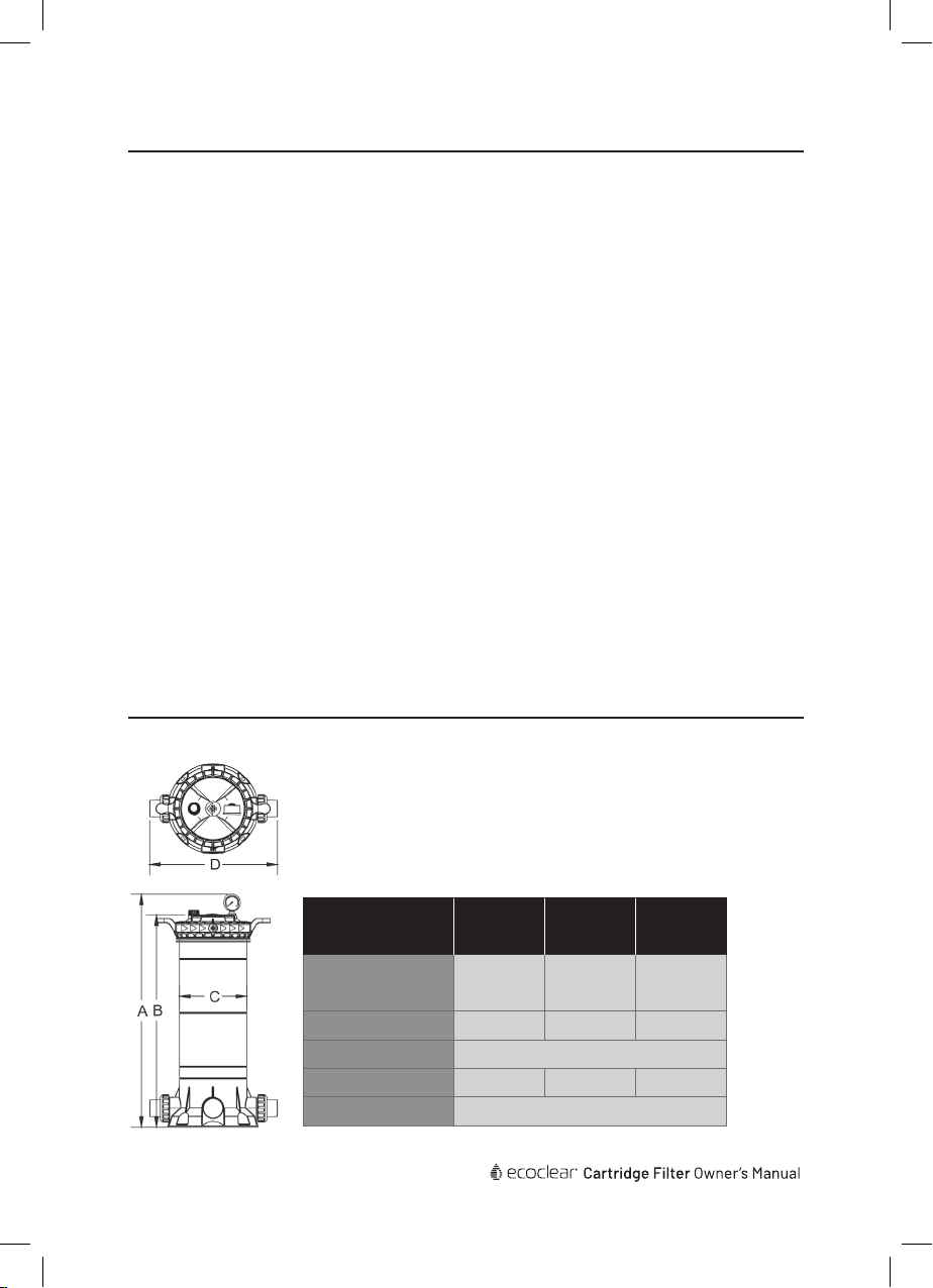
appropriate pump inlet connection orientated towards the pump. Refer to the ‘Specifications’
section for the minimum clearance measurements required for each model.
WEATHER PROTECTION
Ecoclear® cartridge filters are constructed of corrosion resistant materials. However,to ensure
years of reliable performance, it is recommended that the filtration system be adequately
protected from the weather.
ASSEMBLY
Assemble the pressure gauge to the filter lid using Teflon tape on the male thread.
Do not over tighten!
PIPE CONNECTIONS
Piping should be supported independently and not impose heavy loads on the filter or pump.
Use 40mm or 50mm PVC pipe for pump and pool return lines. 50mm should always be used
if length of piping is over 15m. Ecoclear® cartridge filters are supplied with quick connect barrel
unions suitable for 40mm and 50mm PVC pipe. If the pump and filter are located below pool
water level, it is necessary to fit isolating valves in the pipe between the pump and the pool,
and in the return line from the filter to the pool.
1. Pump to filter
Ecoclear® cartridge filters are equipped with two inlet ports marked ‘INLET’. Select the
inlet port most suitable for the installation and plug the other inlet port with blanking cap
provided. Using the supplied barrel unions, connect the pool pump delivery piping to the
selected inlet port couplings, connect the pool pump delivery piping to the selected inlet
port. Use only `P` type plumbing glue. Tighten unions by hand only.
2. Filter to pool Return
Using the supplied barrel unions, connect the pool return piping to the filter fitting marked
‘OUTLET’, the other outlet should be blocked with the blocking cap provided. Tighten
the fitting by hand only. Ensure the o-ring on the fitting is clean, lubricated with o-ring
lubricant and in the correct position.
The filter base is provided with four mounting holes to enable it to be secured, if required.
THE SPARKLING CLEAR WATER DIFFERENCE
INSTALLATION AND OPERATION INSTRUCTIONS

5
FILTER OPERATION
1. Make sure the pump is primed according to manufacturer’s directions.
2. Be sure all valves are open on suction and discharge lines. Ensure the air bleed valve on
the filter lid is open and the lid lock rig is in place and secure.
3. Start the pump. Close the air bleed valve when water is expelled.
4. To determine the correct operating conditions with a clean filter, check that the pressure
gauge reading is 80kpa or below.
5. Record the pressure gauge reading or mark the needle position on the face of the pressure
gauge.
6. Operate the filter for a sucient time to circulate the total pool water volume daily.
The filter should also be operated at all times the pool is in use and for about one
hour afterwards. During winter, the running time may be reduced. Filter operating
requirements will vary for spa applications. Depending upon the system design, type and
size of spa . Consult your builder or spa supplier.
7. When the pressure gauge reading is 50-70kpa higher than the ‘clean filter’ reading as in (5)
above, it is time to clean the cartridge element (see’ Cartridge Cleaning Procedure below).
CARTRIDGE CLEANING PROCEDURE
When the filter gauge reading is 50-70kpa above the clean filter gauge reading cleaning
the single element cartridge is required. To perform the cleaning procedures:
1. Switch o the pump.
2. Close isolating valves on suction and discharge lines where fitted.
3. Open the air bleed valve on the filter lid. unscrew the lock ring and remove the filter lid.
4. Lift out the cartridge element.
5. In most cases the element can be easily cleaned with a garden hose, using good veloc-
ity sprayed directly on the pleats.
CARTRIDGE RE-ASSEMBLY INSTRUCTION
1. Install the cartridge/s and center pipe so that it is located in the bottom spigot.
2. Ensure the filter lid o-ring is clean, lubricated with o-ring lubricant and located in the bottom
groove.
3. Replace the lid and press firmly in place. Screw down the lock ring, hand tight is sucient -
DO NOT OVER TIGHTEN!
4. Make sure the pump is primed according to manufacturer’s directions.
5. Ensure all valves are open on suction and discharge lines.
6. Start the pump.
7. Close the air bleed valve when all air has been expelled.
Note: Algae, calcium, clay, suntan oil and body oils can form a coating on the element
which may not be easily removed with normal hosing. These materials can be
removed by soaking the element in a de-greaser and /or de-scaler.
Your local Maytronics dealer will be able to recommend suitable products.
INSTALLATION AND OPERATION INSTRUCTIONS

6
TROUBLESHOOTING
SYMPTOM CAUSE REMEDY
No Water Discharge
Pool water level too low. Fill pool to correct level.
Air leaks in inlet fittings to
pump.
Check and tighten all
connections. Teflon tape
fittings.
Short filter cycles
Filter Dirty. Clean filter cartridge.
Replace filter cartridge.
Algae present in Pool water.
DON’T RUN FILTER WITH
LIVE ALGAE IN POOL. Check
the chemical condition of
pool water and refer to Pool
Water Chemical Treatment.
Note: Incorrect chemical
treatment will greatly
shorten filter cycle.
Filter start-up pressure high
and water flow low.
Filter requires cleaning. Follow filter cleaning
procedure in this manual.
Return line restricted. Check for flow at return.
Filter start-up pressure low
and water flow high
Skimmer basket full of
leaves or debris.
Clear Skimmer Basket of all
foreign matter and debris.
Pump strainer lid not sealed
correctly.
Refer to pump owners
manual for correct
procedure for sealing
strainer lid correctly.
Pool water level too low. Fill pool correct level.
Pump impeller blocked.
Call an authorised service
agent to service pump.
Blockage in suction line.
Air leak in suction line.
Leaking from filter tank
joint
Tank 0-ring dirty.
Call an authorised service
agent to service pump.
O-ring incorrectly fitted.
O-ring damaged (pinched).

7
REPLACEMENT PARTS
KEY
NO.
PART
NO. DESCRIPTION Q T Y.
1800741
Pressure Gauge With
O-ring (40psi) plus
adapter
1
2800742 Air Release Valve
with o-ring 1
3800743 Ring Lock for
cartridge filter 1
4800744 Cartridge filter Lid 1
5800745 O-Ring for Lid 1
800747 EC100 PVC Air Vent
Pipe With Cover 1
800748 EC150 PVC Air Vent
Pipe With Cover 1
800749 EC200 PVC Air Vent
Pipe With Cover 1
800760 EC100 Element 1
800761 EC150 Element 1
800762 EC200 Element 1
8
Cartridge filter body
not available as
spare part
9
800754 1.5” Union for
Cartridge filters 2
800755 2.0” Union for
Cartridge filters 2
10 800756 Plug 1
11 800757 Internal Pressure
Release Valve 1

PURCHASED FROM:
PURCHASE DATE:
SERIAL NO:
MODEL NO:
IMPORTANT
Please attach your sales invoice/docket here as proof of purchase should warranty service
be required. Please do not return warranty form to Maytronics Australia – Retain for your
records.
Unit 2/91 Rudd Street, Oxley, QLD 4075 | Australia | 1300 693 657 | www.maytronics.com.au
Information contained here in remains the property of Maytronics Australia under Australian copyright law.
Content may not be reproduced or transmitted without our prior written permission.
Disclaimer: Maytronics reserves the right to change product specifications and products details. Product
images are for reference purposes only and may not represent the actual/current product.
©2022 Maytronics Australia Pty Ltd. All rights reserved.
This manual suits for next models
2
Table of contents
Popular Water Dispenser manuals by other brands

Elkay
Elkay VRCHDTL8 Series Installation, care & use manual

US Water Systems
US Water Systems 076-AQT-075 owner's manual

Waterdrop
Waterdrop WD-G3-W instruction manual

Franklin Electric
Franklin Electric XTS Series XTS24 Installation instructions and owner's manual

Nikai
Nikai NWD1206RK instruction manual

Zojirushi
Zojirushi CD-WBC30 operating instructions

BRIO
BRIO Signature Series user manual

Fetco
Fetco HWB-5 user guide

Reflex
Reflex Fillsoft operating instructions

ComAp
ComAp Adoucisseur softeo manual

LAUER
LAUER Aquaboss EcoRO Dia I operating instructions

Franklin Water Treatment
Franklin Water Treatment SWS1C-30-HE Installation instructions and owner's manual