Mazda 0000 81 K11 User manual

Mazda RX-8㧙1
GENUINE SATELLITE RADIO KIT
INSTALLATION INSTRUCTIONS
Thank you for purchasing a genuine Mazda accessory.
Before removal and installation, be sure to thoroughly read these instructions.
Please read the contents of this booklet in order to properly install and use the satellite
radio kit. Your safety depends on it.
Keep these instructions with your vehicle records for future reference.
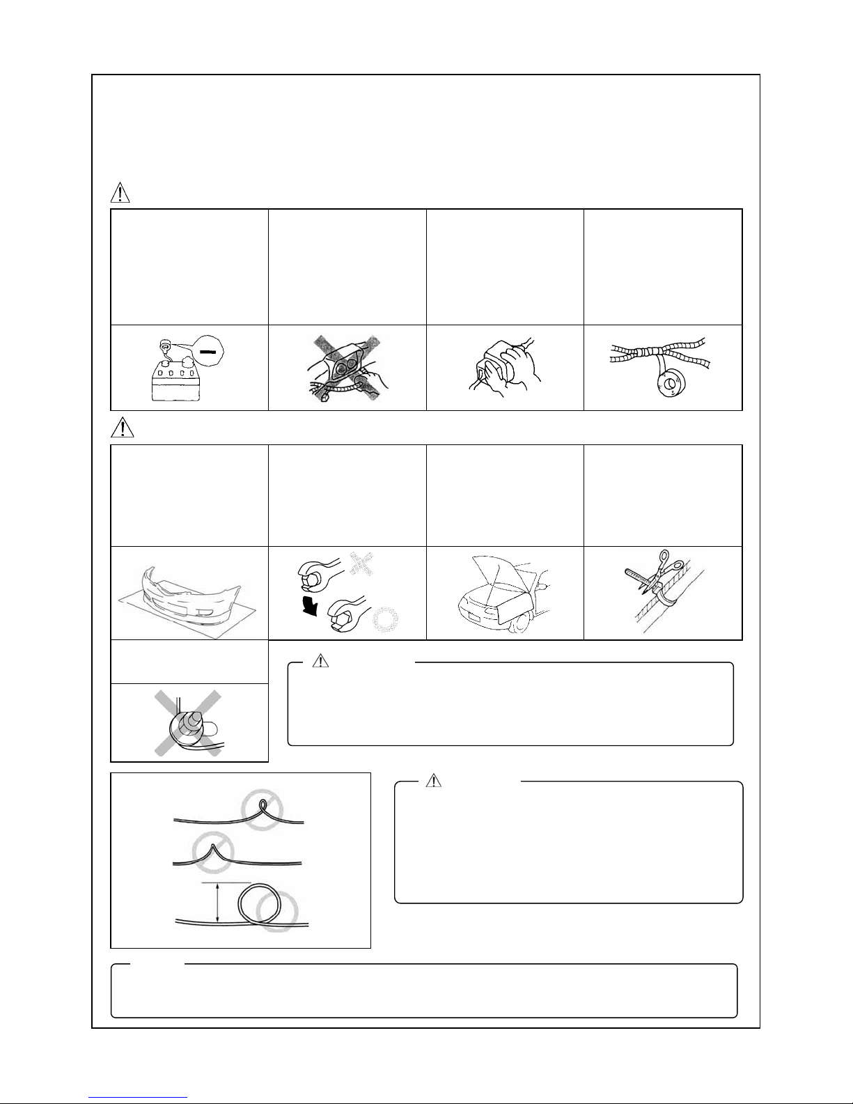
xThere are several WARNING and CAUTION sections in this booklet concerning
safety when installing. Always read and follow them in order to prevent injuries,
accidents, and possible damage to the vehicle.
WARNING: Indicates a situation in which serious injury or death could result if the
warning is ignored.
CAUTION: Indicates a situation in which bodily injury or damage to the vehicle
could result if the caution is ignored.
xIf in any doubt, please ask your Mazda dealer to install the accessory in order to
prevent errors in installation.
xIf you have any questions about the use of the accessory, ask your Mazda dealer for
proper advice before using it.
xMazda and its suppliers are not responsible for injuries, accidents, and damage to
persons and property that arise from the failure of the dealer or installer to follow these
instructions.
xTo ensure safety and reliability of the work, installation, removal and disposal work
done by an Authorized Mazda Dealership is recommended.
xBe careful not to lose removed parts, and be sure that they are kept free from
scratches, grease or other dirt.
PART NAME: SATELLITE RADIO KIT
PART NUMBER: 0000 81 K11 (harness Kit G-X)
VEHICLE: MAZDA RX-8
(Applicable to 2010 model year vehicles and after)
1ED6P11A23900
To the dealer
xPlease turn over these instructions to the customer after installation.
To the customer
xKeep these instructions after installation. The instructions may be necessary for
installing other optional parts or removal of this accessory.
xShould the vehicle or this accessory be resold, always leave these instructions
with it for the next owner.
NOTE
WARNING

Mazda RX-8㧙2
INSTALLATION VIEW
1
DLP unit
Harness (G-X)
A
ntenna cable
A
ntenna
iPod connection cable㩷
To Audio unit
iPod integration module
To AUX connector
Tie redundant part
Harness (G-X)
SIRIUS and iPod
ANTENNA CABLE
HARNESS (G-X)
SIRIUS only
To Audio unit
To AUX connector
Tie redundant part
Harness (G-X)
Electro tap䇼(+B and ACC)䇽
GND
Tie redundant part (GND)
Electro tap䇼(+B and ACC)䇽
GND
Tie redundant part (GND)

Mazda RX-8㧙3
CONNECTION DIAGRAM
<Installation of SIRIUS and iPod integration module>
2
xWhen connecting a connector, be sure to insert it straight along the guide.
The connector terminal may be bent if inserted at an angle.
CAUTION
iPod
(On market product)
DLP unit
(SIRIUS)
Harness (G-X)
Antenna cable
16-pin connector (White)
To AUX or Bluetooth H/F
iPod
integration module
NO CONNECT
iPod connection cable
To Information display
Audio unit
To Vehicle wiring harness
+B
ACC
Audio 24-pin
connector
ACC
+B
16-pin connector
(Gray) 8-pin connector
16-pin connector (Black)
To dashboard member
GND
16-pin connector

Mazda RX-8㧙4
<Installation of SIRIUS only >
xWhen connecting a connector, be sure to insert it straight along the guide.
The connector terminal may be bent if inserted at an angle.
CAUTION
Not used
(Wrap with pad protector)
DLP unit
(SIRIUS)
Harness (G-X)
Antenna cable
16-pin connector (White)
To AUX or Bluetooth H/F
To Information display To Vehicle wiring harness
+B
ACC
Audio 24-pin
connector
ACC
+B
16-pin connector
(Gray)
8-pin connector
16-pin connector (Black)
To dashboard member
Audio unit
GND
16-pin connector

Mazda RX-8㧙5
PARTS
Main Kit (0000 81 Z40)
Part㩷Part name㩷Qty.㩷Part㩷Part name㩷Qty. Part㩷Part name㩷Qty.
Antenna 1 DLP unit 1 Alcohol wipe 1
Nut 2
Harness Kit G-X (0000 81 K11)
Part㩷Part name㩷Qty.㩷Part㩷Part name㩷Qty. Part㩷Part name㩷Qty.
Harness (G-X) 1
Double-sided
adhesive tape 2
Pad protector 19
Urethane 1
Tie wrap
(Small) 21
Tie wrap
(Large) 19
Clip 6
Butyl tape 1
Installation
instructions 1
BEFORE INSTALLATION
Rating Label Removal
1. Tear off lower part of the rating label on the bottom of DLP
unit.
2. If there is nothing written in the Sirius ID (ESN) space of
the rating label, write down the 12-digit number printed in
the location shown in the figure.
3. Affix one rating label in the last page of the Owner’s
Manual.
3
xVerify that the kit includes all the following parts and that they are free of dirt, scratches or damage.
xAll hardware required to install is contained in the 0000 81 Z25 Satellite Radio Kit.
NOTE
4
xThe other rating label is for the dealer (port) records.
xDo not fail to submit the record.
NOTE
DLP unit
Rating label Sirius ID (ESN)
Rating label
Tear off
ԘAffix to the back of the Owner’s Manual.
ԙSubmit to the manager of installation department.
ԙԘ

Mazda RX-8㧙6
REQUIRED TOOLS
Prepare the following tools or items before installation.
䃂Electrical vinyl tape 䃂Mat 䃂Scissors 䃂Scale ٨Phillips screwdriver ٨Torx wrench 䃂Wrench
䃂Socket driver (8 mm, 10 mm, 14 mm) 䃂ISP alcohol
WARNING
When the negative battery
cable is connected during
operation, it may cause
electric shock or other
personal injuries.
Disconnect the negative
battery cable before
removal/installation.
When
connecting/disconnecting
connectors, grasp the
connectors, not the wires.
Otherwise a short, an
accident from poor contact
or fire may occur.
Do not pull the harness
with excessive force. Doing
so can cause a breakage
or a short-related accident,
as well as an electrical
short or fire.
Secure the harness with
the band (part included) so
it doesn’t dangle. If not, it
may cause a short,
accident, or fire.
CAUTION
Put the removed parts and
the parts in the kit on the
protective sheet to prevent
scratches.
Using improper tools may
cause damage and or
broken parts. Use the
correct tool for the job.
Be sure to cover the
vehicle body with
protectors or mats to
prevent stains, scratches
and damage when
removing/installing the
vehicle parts.
Excessive length of tie
wrap may interfere with
other parts and cause
damage.
Cut unnecessary part up to
about 5 mm {0.19 in} from
the fixed point.
Take care not to trap
antenna cable under
attachment nuts.
xWhen the negative battery cable is removed, the clock, radio, trip meters and other memories will be
erased. Before performing work, record the content of the memory.
NOTE
xDuring the installation of the antenna cable make
sure the cable is not pinched, knotted “kinked” or
coiled too tightly. It is recommended that a coil of
less than 20 mm {0.78 in} be avoided if possible.
xIf this wiring procedure is not followed, the
performance of the antenna will be affected and
could result in increased audio muting.
CAUTION
20 {0.78}
mm {in}
xWhen removing/installing the parts, park the vehicle on level ground
and apply the side brake securely. Be sure to turn the ignition switch
off, otherwise the vehicle can move, causing personal injury or
vehicle damage.
WARNING

Mazda RX-8㧙7
PART REMOVAL
Battery cover removal
1. Remove the engine cover.
2. Remove the hose from the battery cover.
3. Remove the battery cover by lifting up from the rear.
Upper panel and ashtray removal
1. Remove the shift knob. (MT vehicles only)
2. Disengage the upper panel clips (6) using a tape-wrapped
flathead screwdriver, and remove the upper panel from
the front console.
3. Remove the ashtray screws (2).
4. Disconnect the connector and remove the assist tray from
the front console.
Lower panel removal
1. Pull the lower part of the lower panel forward to disengage
clips A (2).
2. While pushing the lower panel downward, disengage
hooks B (2) and remove the lower panel.
3. Remove the screws (4), then remove the knee bolster.
(If equipped)
5
En
g
ine cove
r
Battery cover
Hose
Vehicle front
xA short circuit while performing work may cause
damage to parts, electric shock or other injury. Be
sure to disconnect the negative battery cable and do
not allow the terminal to contact any other parts.
WARNING
Clips
A
shtra
y
Upper panel
Screws
Front console
Vehicle front
Connectors
Shift knob
B
Hooks B
Clips A
A
A
B
Vehicle front
Knee bolster Vehicle front
Screws Screws

Mazda RX-8㧙8
Center panel unit removal (Audio-integrated)
1. Remove the bolt (1).
2. Remove the screws (2).
3. Pull the center panel unit outward, then remove clips A (5).
4. Remove the air conditioner side connector.
5. Disconnect the audio side connectors (2), the antenna
feeder (1 location), and then remove the center panel unit.
Speaker grille removal
1. Press the area (1) in the direction of the arrow shown in
the figure.
2. Raise the speaker grille in the direction of the arrow (2)
and pull it out in the direction of the arrow (3).
3. Pull up the speaker grille in the direction of the arrow (4)
and disengage the speaker grille clips A (6).
4. Pull out the speaker grille from the fulcrum point of each
tab B.
xAlways wear gloves when working to protect the
special paint treatment of the center panel unit.
xIf the painted surface becomes dirty, use a soft cloth
to wipe it clean.
CAUTION
xDo not apply excessive force when pulling out the
center panel; otherwise it could cause an open circuit.
xWhen installing the center panel unit, make sure that
the harness and the antenna feeder are not caught.
CAUTION
Center panel unit
Audio side connectors
Bolt
Screws
Clips A
Antenna feeder
䌁
䌁
䌁䌁
䌁
Ai
r
Conditioner
side connector
Vehicle front
Vehicle front
Clips A
Speaker㩷grille㩷
Vehicle front
Speaker grille
Tabs B
Press
<Speaker㩷grille removal note>㩷
Pull

Mazda RX-8㧙9
Center panel removal
1. Remove the center panel screws (2).
2. Pull the center panel outward and disengage tabs A (4).
3. Disconnect the hazard switch connector and remove
the center panel.
Information display removal
1. Remove the screws (2).
2. Pull the information display outward, disconnect the
connector and remove the information display.
Glove compartment removal
1. Pull the stay damper in the direction shown in the figure,
and detach the connecting part between the glove
compartment and stay damper.
2. Press the stoppers in and removal them.
3. Lower the glove compartment.
4. Detach the clips from the dashboard and remove the
glove compartment.
Inner scuff plate (passenger’s side) removal
1. Pull the inner scuff plate upward, detach clips A from the
body, and then remove the inner scuff plate.
Information display㩷
Screws
Connector
Vehicle front
A
A
A
A
A
A
A
Cli
p
A
Inner scuff plate
Vehicle front
Glove compartment
Clip
Stopper Stopper
Stay damper
Vehicle front
Center panel㩷
Vehicle frontScrews㩷
Tabs A㩷

Mazda RX-8㧙10
Front side trim (passenger’s side) removal
1. Partially peel back the seaming welt.
2. Pull the front side trim in the direction of the arrow and
detach clips A and locator pin B.
3. Detach the tab D, then remove the front side trim.
Rear seat (passenger’s side) removal
1.Lift the point A in the direction of the arrow, then remove
the rear seat cushion.
2. Remove the bolts, then remove the rear seat back.
Tire house trim (passenger’s side) removal
1. Partially peel back the seaming welt.
2. Pull the tire house trim outward and detach clips A and
locator pins B.
3. Detach tabs C and removal the tire house trim.
Trunk end trim removal
1. Remove the fasteners.
2. Pull the trunk end trim upward, then detach clips A, locator
pins B, and tabs C.
3. Remove the trunk end trim.
A
Front side trim Tab C
Clip A
Locator pin B
A
D
C
B Vehicle front
Locator pin B
Fasteners
Trunk end trim
Clip A
Fasteners
A
B
A
B
C
C
C
Vehicle front
A
Rear seat back
Bolt (12 mm)
17㧙20 N㨯m
{1.8㧙2.5 kgf㨯m,
13㧙18 ft㨯lbf}
Rear seat cushion
A
Tire house trim
Clip A
Tab C
Locator pin B
A
A
B
A
CB
C
C
B
Vehicle front

Mazda RX-8㧙11
Trunk side trim (passenger’s side) removal
1. Remove the fasteners, then remove the trunk side trim.
Rear combination light (driver’s side) removal
1. Disconnect the connector.
2. Remove the screw.
3. Remove the rear combination light.
Nuts (8 mm)
3.9㧙5.9 N㨯m {40㧙60 kgf㨯cm, 35㧙52 in㨯lbf}
Connector
Rear combination light
Vehicle front
Fasteners
Trunk side trim
Vehicle front

Mazda RX-8㧙12
INSTALLING DLP UNIT
1. Remove the bushes (4 locations), brackets (2 locations),
washers (4 locations), and screws (4 locations) from the
DLP unit.
2. Affix pad protectors to the DLP unit as shown in the
figure.
3. Cut off the excess part of pad protectors.
4. Adhere double-sided adhesive tapes to the top of the pad
protectors.
5. Affix pad protector half to the DLP unit as shown in the
figure.
6
Pad protectors
DLP unit
Double-sided adhesive tapes
Pad protectors
DLP unit
Cut
xTo ensure proper affixing, be sure to degrease the
area where the pad protector is affixed.
CAUTION
Pad protecto
r
1/2 DLP unit
DLP unit
Bracket
Bush
Washe
r
Scre
w
Bracket
Bush
Washe
r
Scre
w
xThe brackets are not used with the installation of this
accessory.
Note
xTo ensure proper affixing, be sure to degrease the
area where the pad protector is affixed.
CAUTION

Mazda RX-8㧙13
6. Secure the tie wraps (large) to the DLP unit with a pad
protector as shown in the figure.
7. Install the DLP unit to the inside of the side body panel of
the trunk compartment using tie wraps (large).
(With the connector towards the front of the vehicle.)
Pad protecto
r
Tie wraps (large)
DLP unit
120 {4.72}
mm
{
in
}
Tie wraps (large)
DLP unit
Side body panel
Vehicle front
A
lign side of DLP unit with
line of side body panel
xWhen securing the DLP unit, be sure to align the side
of the DLP unit with the line of the side body panel.
If it deviates rearward of the side body panel line,
the DLP unit will interfere with the trunk side trim and
cannot be installed.
xTo ensure proper affixing, be sure to degrease the
area where the double-sided adhesive tape is affixed.
CAUTION

Mazda RX-8㧙14
INSTALLING ANTENNA
1. Clean the adhesion area on the trunk lid with isopropyl
alcohol (IPA).
2. Install the antenna in the position shown in the figure.
3. Clean the adhesion area on the trunk lid with isopropyl
alcohol (IPA).
4. Attach the clips to the trunk lid.
5. Install the antenna cable to the clips.
6. Secure the antenna cable to the vehicle wiring harness with
tie wraps (small).
7
xIt is critical that the antenna follows the route as
shown. Failure to follow this route will not provide the
slack required to open and close the trunk lid.
xDo not remove trunk seam from the flange. The
antenna cable must not interfere with the flange
seals.
CAUTION
A
dhesion area
100 {3.93}
mm {in}
Cente
r
100 {3.93}
Trunk lid
Vehicle front
A
ntenna
Cente
r
Trunk lid mm
{
in
}
618
{
24.33
}
15㧙20
{0.54㧙0.78}
Vehicle front
A
ntenna cable
mm {in}
<Cross-sectional view>
Clip
Clips
(100 {3.93} interval)
Vehicle front
A
ntenna cable
Tie wraps (small)
Vehicle front
xTo ensure proper affixing, be sure to degrease the
area where the double-sided adhesive tape is affixed.
CAUTION

Mazda RX-8㧙15
7. Pull the seaming welt up slightly on the flange and route
the antenna cable under the outside lip.
8. Clean the adhesion area with isopropyl alcohol (IPA).
9. Secure the antenna cable in place with butyl tape and
pad protector halves.
10. Secure the antenna cable to the vehicle wiring harness
with tie wraps (small).
11. Secure the antenna cable to the vehicle wiring harness
with tie wraps (small).
12. Secure the antenna cable to the vehicle wiring harness
with tie wraps (small).
xBe careful not to tear the seaming welt when puling it out.
xDo not remove trunk seam from the flange. The antenna
cable must not interfere with the flange seals.
CAUTION
Antenna cable
Tie wraps (small)
Vehicle wiring harness
Vehicle front Tie wraps (small)
xDuring the installation of the antenna cable make
sure the cable is not pinched, knotted “kinked” or
coiled too tightly. It is recommended that a coil of less
than 20 mm {0.78 in} be avoided if possible.
xIf this wiring procedure is not followed, the
performance of the antenna will be affected and
could result in increased audio muting.
CAUTION
Antenna cable
Tie wraps (small)
Vehicle wiring harness
Vehicle front
Tie wraps (small)
xTo ensure proper affixing, be sure to degrease the area
where the pad protector is affixed.
xDo not wrap butyl tape around flange.
xDo not double-layer tape.
Butyl tape should hold the antenna cable to the sheet
metal as shown.
xTake care not to trap antenna cable under attachment
nuts.
CAUTION
Seaming welt Antenna cable
Vehicle front
Pad protector halves should
be below the body crease.
Body crease
mm
{
in
}
No interference of butyl tape with body
projection or within 10 mm of hole
Butyl tape
Antenna cable
Do not put
pad protectors
within 35 {1.37}
of opening
Pad protector 1/2
10-15
{0.39-0.59}
40 {1.57}

Mazda RX-8㧙16
13. Secure the antenna cable to the vehicle wiring harness
with tie wraps (small).
14. Connect the antenna cable to the DLP unit.
15. Bundle the redundant part of the antenna cable into a loop
and affix it to the vehicle panel using pad protector halves.
INSTALLING iPod INTEGRATION MODULE
Preparation for iPod integration module installation
1. Affix the tie wrap (large) to the iPod integration module
with a pad protector (1) as shown in the figure.
2. Affix the pad protectors to the iPod integration module as
shown in the figure.
xTo ensure proper affixing, be sure to degrease the
area where the pad protector is affixed.
CAUTION
iPod integration module
Pad protector
Tie wrap (large)
iPod integration module
Pad protector㩷1/2 x 1
Pad protectors㩷1/3 x 3
xTo ensure proper affixing, be sure to degrease the
area where the pad protector is affixed.
CAUTION
xWhen installing Sirius only, begin with Step 1 on page 21.
NOTE
8
xBundle the antenna cable into a loop and attach it to
the sheet metal on the interior side of the trunk, and
secure with pad protector halves.
NOTE
Antenna cable
Tie wraps (small)
Pad protector 1/2
DLP unit
Vehicle front Vehicle wiring harness
xBe sure to bundle the harness into a loop.
xTo ensure proper affixing, be sure to degrease the
area where the pad protector is affixed.
CAUTION

Mazda RX-8㧙17
3. Connect the harness (G-X) and iPod connection cable to
the iPod integration module.
4. Fold back the harness (G-X) and affix it to the iPod
integration module using a pad protector as shown in the
figure.
5. Remove the vehicle wiring harness clip from the bracket.
6. Secure the tie wrap (large) installed on the iPod
integration module to the vehicle wiring harness on
the back of the dashboard.
iPod integration module
Vehicle wiring harness
Vehicle front
Tie wrap (large)
xTo ensure proper affixing, be sure to degrease the
area where the pad protector is affixed.
CAUTION
iPod integration module
Pad protector
Harness (G-X)
iPod connection cable
Vehicle wiring harness clip
Bracket
Bracket
Vehicle front
Vehicle front

Mazda RX-8㧙18
INSTALLING THE HARNESS
Installation of SIRIUS and iPod integration module
1. Route the harness (G-X) to the back of the center panel
unit and to the back of the information display.
2. Affix the pad protector to the dashboard as shown in the
figure.
3. Insert and connect the harness (G-X) to the Information
display 12-pin connector.
4. Secure the harness (G-X) to the vehicle wiring harness
with tie wrap (small).
9
iPod integration module
Harness (G-X)
Vehicle front
iPod connection cable
㿈
xTo ensure proper affixing, be sure to degrease the
area where the pad protector is affixed.
CAUTION
Vehicle front
Pad protector
Dashboard
Vehicle wiring harness
Vehicle front
Tie wrap (small)
Harness (G-X)
Information display 12-pin connector
mm {in}
100 {3.93}

Mazda RX-8㧙19
5. Affix a pad protector on the information display connector.
6. Wrap a pad protecor around the rear side of the harness
(G-X) 16-pin connector.
7. Connect the harness (G-X) 16-pin connector to the AUX,
Bluetooth H/F connector.
8. Affix the pad protector half to the dashboard member as
shown in the figure.
9. Insert the harness (G-X) GND wire between the
dashboard and the dashboard member and secure it
using the vehicle bolt.
10. Bundle the redundant part of harness (G-X) GND wire
and secure it to the harness (G-X) using a tie wrap
(small).
Vehicle front
Harness (G-X)
Pad protector
xTo ensure proper affixing, be sure to degrease the
area where the pad protector is affixed.
CAUTION
AUX, Bluetooth H/F
To Audio unit
Pad protector
Vehicle front Harness (G-X) 㿉
㿈
Harness (G-X)
(16-pin connector)
xTo ensure proper affixing, be sure to degrease the
area where the pad protector is affixed.
CAUTION
To AUX connector
To Audio unit
Pad protector 1/2
GND
Vehicle front
Tie wrap (small)
Harness (G-X)
㿉
㿈
Vehicle bolt
xMake sure the ground eyelet contacts the steel
bracket.
CAUTION

Mazda RX-8㧙20
11. Branch connect the +B wire to the audio 24-pin connector
(terminal B) using the electro tap.
12. Branch connect the ACC wire to the audio 24-pin
connector (terminal R) using the electro tap.
Audio 24 pin connector (Vehicle wire) Kit
㩷
wire
Terminal B +B
Terminal R ACC
13. Wrap the electro taps and vehicle wiring harness together
using urethane.
14. Secure the harness (G-X) +B, ACC wires to the vehicle
wiring harness with tie wraps (small).
15. Hook the harness (G-X) to the A/C unit and secure it.
16. Secure the harness (G-X) to the side of the heater duct
using a pad protector as shown in the figure.
17. Secure the iPod connection cable to the dashboard
member using a tie wrap (small).
18. Bundle the iPod connection cable redundant part and
secure it using a tie wrap (large).
19. Wrap both looped ends of the excess iPod connection
cable with pad protectors.
20. Push the bundled harness into the back of the dashboard.
21. Go to Step 16 on page 24.
Pad protector Tie wrap (small)
Remove connector cover when connecting
iPod; fit connector cover when iPod is not used
Put iPod connection cable in glove box
(Cable 30 cm from instrument panel)
Tie redundant
part
iPod
integration module
Tie wrap (large)
Pad protectors
Vehicle front
Dashboard
Dashboard member
Heater duct
㿈
xTo ensure proper affixing, be sure to degrease the
area where the pad protector is affixed.
CAUTION
Urethane
Tie wraps
(small)
Terminal B: +B
Kit wire: +B
Terminal R: ACC
Kit wire: ACC
RB
[Audio 24 pin connecto
r
]
(View from wire side of connector)
Vehicle wiring harness Electro-taps
Harness (G-X)
(+B, ACC wires)
Vehicle front Hook
This manual suits for next models
1
Table of contents
Other Mazda Car Receiver manuals