Mazda 0000-8F-N10 User manual

1
Accessory RSE System
INSTALLATION INSTRUCTIONS
Thank you for purchasing this Mazda accessory.
Before removal and installation, be sure to thoroughly read these instructions.
Please read the contents of this booklet to properly install and use the RSE system. Your
safety depends on it.
Keep these instructions with your vehicle records for future reference.
!WARNING
• There are several !WARNING and !CAUTION sections in this booklet concerning safety
when installing or removing the RSE system. Always read and follow them to prevent injuries,
accidents, and possible damage to the vehicle.
!WARNING: Indicates a situation in which serious injury or death could result if the warning
is ignored.
!CAUTION: Indicates a situation in which bodily injury or damage to the vehicle could result
if the caution is ignored.
• Forareasindicatingthetighteningtorqueinthisinstructionmanual,tightentothespecied
torque using a torque wrench.
• Do not modify the RSE System.
• Do not install the RSE system or remove in any way other than described in the following
instructions.
• If in any doubt, please ask your Mazda dealer to install the accessory to prevent errors in
installation.
• If you have any questions about the use of the accessory, ask your Mazda dealer for proper
advice before using it.
• Mazda and its suppliers are not responsible for injuries, accidents, and damage to persons
and property that arise from the failure of the dealer or installer to follow these instructions.
• To ensure safety and reliability of the work, installation, removal and disposal work must be
carried out by an Authorized Mazda Dealership.
• Be careful not to lose removed parts, and be sure that they are kept free from scratches,
grease, or other dirt.
PART NAME: Rear Seat Entertainment System
Vehicle: Mazda CX-9
Part Number: 0000-8F-N10
To the dealer
• Please turn over these instructions to the customer after installation.
To the customer
• Keep these instructions after installation. The instructions may be
necessary for installing other optional parts or removal of this accessory.
• Should the vehicle or this accessory be resold, always leave these
instructions with vehicle for the next owner.
NOTE

2
A. PARTS
• Before installation, verify that the kit includes all the following parts and that they are free of
dirt, scratches, or damage.
NOTE
Installation View
Figure 1
Monitor A Monitor B
AUX Audio
Module
Power
Connection
Power
Connection
GMSL
Connection
Part Part Name Service Part
Number
Qty. Part Part Name Service Part
Number
Monitors
Monitor A 0000-8F-N32
600069 1
Monitor B w/
DVD
0000-8F-N33
620070 1
Mazda
Installer
Prepack
Harness -
Power / Ground
0000-8F-N40
103626
1 Harness -
GMSL Coax
0000-8F-N42
103627
1
Harness -
Vehicle Aux
0000-8F-N41
103628 1
Harness - Aux
Control Box
0000-8F-N39
103629 1
Aux Audio
Module
0000-8F-N37
610018 1
Mazda
Customer
Prepack
Headphone W/
Batteries 0000-8F-N34 2
Remote Con-
trol
W/Battery
0000-8F-N35 2
Owner’s Manual 0000-8F-N43 1
Install
Hardware
Kit
6” Tie Wrap
(Small)
N/A
19
ADHESION
PROMOTER
Loremipsumdolor sit amet, consectetuer adipiscing elit, sed diam nonummy nibh euismod
tinciduntutlaoreet dolore magna aliquam erat volutpat. Ut wisi enim ad minim veniam, quis
nostrudexercitation ullamcorper suscipit lobortis nisl ut aliquip ex ea commodo consequat.
Duisautemvel eum iriure dolor in hendrerit in vulputate velit esse molestie consequat, vel illum
doloreeufeugiat nulla facilisis at vero eros et accumsan et iusto odio dignissim qui blandit
praesentluptatumzzril delenit augue duis dolore te feugait nulla facilisi.
Loremipsumdolor sit amet, cons ectetuer
Loremipsumdolor sit amet, consectetuer adipiscing elit, sed diam nonummy nibh euismod tincidunt
utlaoreetdolore magna aliquam erat volutpat. Ut wisi enim ad minim veniam, quis nostrud exerci
tationullamcorpersuscipit lobortis nisl ut aliquip ex ea commodo consequat. Duis autem vel eum iriure
dolorinhendrerit in vulputate velit esse molestie consequat, vel illum dolore eu feugiat nulla facilisis at
veroeroset accumsan et iusto odio dignissim qui blandit praesent luptatum zzril delenit augue duis
doloretefeugait nulla facilisi.
Loremipsumdolor sit amet, cons ectetuer
Promoter N/A
1
Ferrite
Core
N/A
2
Foam Tape N/A
5
Wire Puller
N/A
1 Foam Pads
(sheet of 3)
N/A
4

3
REAR HEADREST
(Driver Side)
AUDIO
RELAY
BOX
OEM AUX
PLUG
OEM Sound (Vehicle Harness-U nder Center
Console)
5A FUSE
5A FUSE
(3-Way Audio, (+B/ACC,
G ro u n d)). H arn ess. P/ N:1 036 29
Audio fromR.S.E to
A.R.B
P /N:103628
Vehicle OEM Power (Connection
made under driver seat)
REAR HEADREST
(Passenger Side)
Yazaki (7 187 -8854)
4- Way Connector, C1
Sumitomo (6098-57 04)
12-way connector, C1
GMSL Cables
(SMC connectors)
Unde r Center Console
(200 mA current consumption from+B or ACC)
Sumitomo (6098-57 13) 1 2-way
connector
Sumitomo (6098-57 13) 1 2-way connector, C3
Power & Ground
P /N:103626
Power & Ground
P/N:103626
AB
Rear Seat
Entertainment
Monitor Assembly Mo n itor Assembly
P / N : 103 627
3- P lace Connector, C1
Molex43645-03 00
14-Way Connector, C2, Molex 43025-14 00
Power Filter Power Filter
2-Way connector, C3
JOWLE C4202H-2X1 P
2-Way connector, C2
JOWLE C4202H-2X1 P
3-Way connector, C2
Molex43645-0 300
B. WIRING DIAGRAM

4
C. BEFORE INSTALLATION
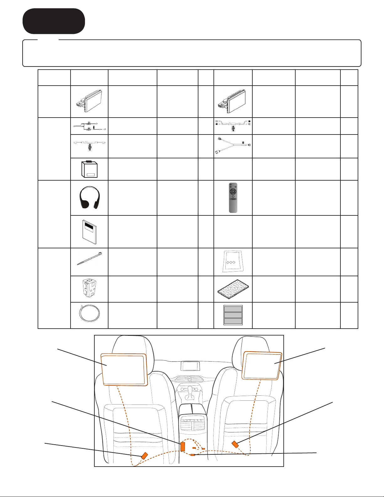
• REQUIRED TOOLS
• Wrapped pliers Nylon tool Diagonal cutter Electrical tape
10mm wrench Flashlight Gloves
• To perform the installation work safely and maintain functionality and quality, thoroughly read
these instructions before performing the procedures and always heed the warnings and precautions.
• In the work procedures, there are descriptions which are only indicated in the illustrations.
Make sure to follow these procedures as well.
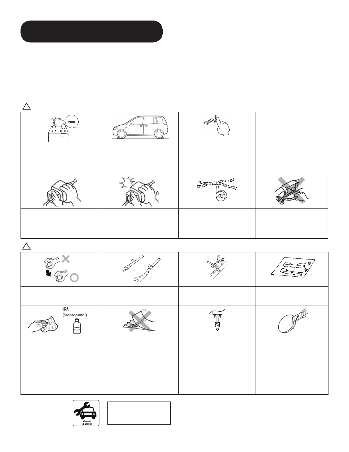
!WARNING
When the negative battery is
connected during operation, may
cause electric shock or other
personal injuries. Disconnect the
negative cable before installation.
Before performing any work, park
the vehicle on level ground, apply
the parking brake securely, and
then block the wheels.
Be careful when handling drills and
other sharp objects. If not handled
properly it could result in serious
injury.
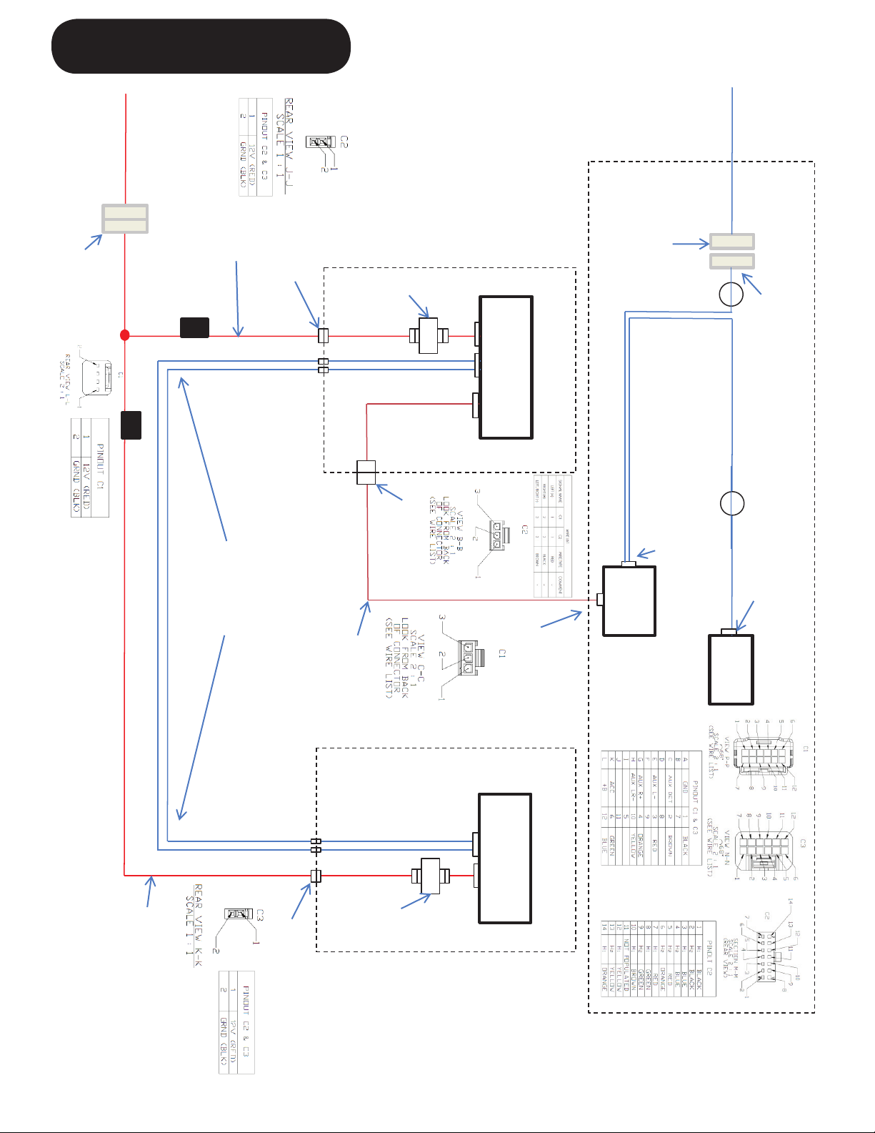
When connecting/disconnecting
connectors, grasp the connectors,
not the wires. Otherwise a short and
anaccidentfrompoorcontactorre
may occur.
Make sure the connector is
securely pressed in until a click
soundisheard.Otherwiseareor
other accident may occure due to
an open circuit or poor contact.
Secure the harness with the
band (part included) so it doesn’t
dangle. If not, it may cause a short,
accident,orre.
Do not pull the harness with
excessive force. Doing so can
cause a breakage or a short-
related accident, as well as an
electricalshortorre.
!CAUTION
Using improper tools may cause
damage and/or broken parts. Use the
correct tool for the job.
Wrap protective tape around screw-
drivers and fastener remover tools
to prevent scratching the vehicle.
Excessive length of tie wrap may
interfere with other parts and cause
damage.
Put the removed parts and the
parts in the kit on the protective
sheet to prevent scratches.
If there is dust, dirt or grease on
the adhesion surface, the adhesive
strength of the double-sided adhesive
tape will splotch and adhesive power
of the tape will be reduced. Wash and
degrease the surface of the adhesion
area before applying the double-
sided adhesive tape. Be sure to wash
interior and exterior parts using IPA
(isopropyl alcohol).
If tape or a mount base is
re-adhered, the adhesive
strength will be weakened.
Before adhering, accurately
determine the adhesion position.
When drilling, hold the drill or hole
saw perpendicular to the drilling
surface to prevent the drill position
from deviating.
Make sure to remove burrs from
the surface so that the bumper
surface is smooth.
Advice Refer to the Workshop
Manual for removal and
installation of vehicle parts.

5
D. SEAT POSITIONING
■ Move both front seats to fully back, fully raised (if equipped) and reclined positions. Reclined position
should allow for removal of factory headrest with enough clearance to avoid contacting the headliner.
E. PREPARATION FOR INSTALLATION
Negative Battery Cable
Vehicle Front
• Be careful not to damage or lose any parts removed from the vehicle since they will be reused.
!CAUTION
Negative Battery Cable Disconnection.
1. Set the selector lever to the P position.
(AT vehicles only)
2. Disconnect the negative battery cable and
wrap tape around it to insulate.
Tightening torque: 4.0-6.0 N-m
• When removing/installing the parts,
park the vehicle on level ground and
apply the side brake securely. Be sure
to turn the ignition switch off, otherwise
the vehicle can move, causing personal
injury or vehicle damage.
!WARNING
• If the negative battery cable is connected
while performing the work, it may cause
electrocution or other personal injuries.
Disconnect the negative battery cable
before removal/installation.
!WARNING
Figure 2
F. DRIVER SIDE HEADREST REMOVAL
1. From the 2nd row, depress release button on left
side factory guide sleeve and remove headrest.
2. Be careful not to strike headliner when removing
headrest from seat.
3. Set the headrest aside in a safe location.
Figure 3

6
G. POST GUIDE SLEEVE REMOVAL
1. From the 2nd row, unclip J-clip at the bottom of the seat
back.
2. Locate the zippers at the bottom of either side of the
seat. The zippers may be tie wrapped to the seat
harness. If so, cut the tie wraps to access the zippers.
3. Pull the zipper up with wrapped pliers until fully
unzipped. (Figure 4a)
4. Disengage the 6 clips in the seat back that secure the
seat cover to the seat frame. (Figure 4b)
Note: Only the top 2 clips are included in the passenger
side seat for the Sport trim level
!CAUTION - Gloves are recommended for steps 4
and 5 to avoid injury or cuts to your hands.
5. Reach up through the remaining seat material until you
can feel the bottom of the guide post sleeves.
6. Remove the head rest guide sleeves.
a. Press the locking tabs in at bottom of the post guide
sleeves on both sides of the LH post
b. Lift up and out of the seat and seat frame. (Figure 5)
7. Repeat steps 5 and 6 on the RH sleeve.
8. Discard the removed post guide sleeves.
Figure 4a
Figure 5
a. Squeeze locking
tabs to release.
J-Clip
Figure 4b
Zippers
Tie wrap (if available)
b. Lift to
release

7
Figure 7
Figure 8
1. Pull the Seat Top RSES Assembly A from packaging,
leavingtheprotectivelmonthemonitor.
2. Carefully unwrap all cables from the base of the monitor.
3. While sitting in the 2nd row, locate the left side opening
on the top of the seat.
4. Grasp the Power/Ground and GMSL connectors and
insert between the right side of the seat frame and the
seat material. (Figure 6)
5. Locate the right side opening on the top of the seat.
6. Grasp the AUX Audio Cable connector and insert
between the left side of the seat frame and the seat
material.
7. Hold the monitor and position the RSES post guide
sleeves directly over the openings in the top of the seat.
8. Reach into the seat back, grasp all three connectors and
carefully pull them to the bottom of the seat frame.
!CAUTION – Do not contact, or secure RSES
wiring to airbag device or any airbag wiring!
9. Insert the monitor guide sleeves into the seat and push
downward with consistent and even pressure on both
sides of the monitor base until the guide sleeves are half
way into the seat. (Figure 7)
10.Grasp all connectors again and carefully pull to the
bottom of the seat.
11. Continue inserting, gradually pulling the cables fully to
the bottom of the seat, until they are fully inserted.
12.Oncethesystemisfullyseated,abertoolmaybe
usedtoevenoutthecablessotheyarelyingatagainst
the metal seat frame. This will minimize the chance of
seeing cables from the front seat.
H. DRIVER SIDE RSES INSTALLATION
Figure 6
SeatTop-RSESAssembly B
MN
IC
FCC
S/N
Loremipsumdolor sit amet, consectetuer adipiscing elit, sed diam
nonummynibheuismod tincidunt ut laoreet dolore magna aliquam erat
volutpat.Utwisi enim ad minim veniam, quis nostrud exerci tation
ullamcorpersuscipitlobortis nisl ut aliquip ex ea commodo consequat.
Duisautemvel eum iriure dolor in hendrerit in vulputate velit esse
molestieconsequat,vel illum
Locking Tabs
!CAUTION - Verify the guide sleeves are fully seated by reaching into the seat back and
feeling the locking tabs at the bottom of the seat frame tube. Locking tabs should extend
out below seat frame tube and not be compressed. Pull up on the monitor base to verify it
does not begin to pull out of the seat frame. (Figure 8)

8
1. Grasp the Power/Ground, GMSL, and AUX Cables in
the seat back.
!CAUTION - Do not tie wrap any harnesses to the
airbag side of the seat!
2. Hold the cables together and pull to right side of seat.
Secure all 3 cables with a tie wrap to the seat frame on
the right side of the seat. The tie wrap goes around the
cables, the vertical yellow portion of the frame, and over
the 2nd crossbar down. (Figure 9)
3. Locate the silver line on the GMSL cable. Clamp the
ferrite core aligning the top of the core with the mark on
the cable. Wrap the ferrite core with a foam pad.
(Figure 10)
I. SECURING CABLES IN DRIVER SIDE SEAT BACK
Figure 9
Tie Wrap
2nd Crossbar Down
!Airbag
Location
Figure 10
Ferrite Core
Silver Line
GMSL
Cable

9
J. ROUTING CABLES THROUGH DRIVER SIDE SEAT
1. Following the factory seat wiring harness, route all of the
connectors through the opening in the foam at the right
side base of the seat opening.
2. Continue following the factory seat wiring harness
through the opening in the cloth material.
3. Carefully pull all of the wiring through until all of the
excess wiring has passed through the opening.
4. Use a tie wrap to attach all 3 wires to the bottom of the
seat frame on the yellow tab. (Figure 11).
5. Pull all three cables inside of felt cover under bottom
right side of seat, and feel for 2nd coil towards front of
vehicle. Use a tie wrap to secure all 3 harnesses to this
coil. (Figure 12).
6. Remove the RSES Power/Ground harness from the
Installer Prepack.
7. Whileintherstrow,locatetheaccessorypower
connection point, taped to the factory wiring harness
underneath the driver’s front seat. (Figure 13)
8. Connect the large WHITE connector of the Power/
Ground harness to the accessory power harness.
!CAUTION – Do not contact, or secure RSES
wiring to airbag device or any airbag wiring!
9. Route all 3 cables along the corrugated factory seat
harness, and use foam from the sheet of 3 pieces of
foam tape to secure in the three evenly spaced locations
illustrated in Figure 13. Two overlapping pieces of foam
tape should be used at each location to wrap completely
around the factory seat harness. The cables should
come in contact with the seat harness through the length
of the harness to allow the RSES Harness to move as
the seat slides, without getting pulled, pinched, or caught
in any moving parts. (Figure 14)
Figure 11
Figure 13
Tie Wrap Yellow
Tab
Figure 12 (view is from
under seat looking up)
Tie Wrap
Seat Harness
Accessory
Power
Foam Tape

10
K. CONNECTING CABLES
1. Connect 2 pin connector for the Power/Ground cable to
the 2 pin female connector on the Power/Ground RSES
Harness that is on the shorter length of the cable.
2. Remove the GMSL Coax RSES harness from installer
prepack. Connect RED to RED and BLUE to BLUE of
cable to the GMSL cable laying under the driver’s seat.
3. Remove the AUX Control Module RSES harness from
the installer prepack. Connect this cable to the 3 pin
female connector on the AUX Audio Cable laying under
the driver’s seat.
1. While sitting in the 2nd row, open the top center console
doors.Useabertooltoseparatethebackpanelofthe
center console from the rest of the structure. Insert the
toolandpullthebertoolandpaneltowardstherearof
the vehicle. (Figure 15)
2. Pullfromthetopofthepanelrsttodisengagethetop
3 clips, then continue to pull to disengage remaining 4
clips, 2 on either side of the center console back panel.
(Figure 16)
3. The panel will still be held to the center console by a
harness with 2 Christmas tree clips and a large white
cable connector. Do not remove the Christmas tree
clips or the connector from the panel. Slightly rotate
the panel towards the rear of the vehicle and remove
2 of the 4 screws indicated in Figure 16a. Then rotate
the panel back in the other direction and remove the
remaining 2 screws. Remove the console panel and
place it in a safe location where it will not get damaged
or lost.
L. ROUTING CABLES THROUGH CENTER CONSOLE
Figure 14
(Power/Ground)
(GMSL Cable)
(AUX Control Module)
Figure 15
Figure 16a
Figure 16
Clips
Remove 4 Screws

11
4. Disengage the air vent duct push clips and remove the
air vent duct. Set the air vent duct and push clips aside
in a safe location. (Figure 17)
5. Feed the wire puller into lower left section of the center
console. The wire puller will feed between carpet and
console towards the front of the vehicle, and the opening
of the carpet under the driver side seat. (Figure 18)
6. From the front row driver seat, tape the long end of the
Power/Ground, GMSL, and AUX Cables to one end of a
wire puller. (Figure 19)
7. Grasp the wire puller from the rear seat, and carefully
pull the connectors and remaining length of cable
through and out of the center console opening as
illustrated in Figure 18.
!CAUTION - When pulling the cables underneath
the carpet, if the cable begins to feel stuck or caught
on something while pulling the connectors or cable
through the carpet, STOP and verify they are free
before pulling any further to avoid damaging the
connectors or cable.
8. Remove the tape from the AUX Control Module Cable
only, and then reapply the tape securing the Power/
Ground and GMSL cables to the wire puller.
9. Feed the wire puller into lower right section of the center
console. The wire puller will feed between carpet and
console towards the front of the vehicle, and the opening
of the carpet under the passenger side seat.
10.Locate the end of the wire puller at the opening in the
carpet underneath the passenger seat. (Figure 20)
11. Grasp the wire puller and carefully pull the remaining
length of cable from the center console to underneath
the passenger’s seat. (See !CAUTION in step 7)
12.Remove the tape securing the cables to the wire puller
andlaythemontheoorunderneaththepassengerside
seat (Figure 20)
Figure 17
Figure 18
Figure 20
Push Clips
Driver Side
Routing
To Carpet
Opening
Under Seat
Figure 19
RSES Cables
Wire
Puller
RSES
Cables

12
M. AUX CONTROL BOX CONNECTIONS AND MOUNTING
1. Remove AUX Control Module and vehicle AUX harness
from the installer prepack.
2. Connect the 14 pin connector of the AUX Harness to
the corresponding connection point on the AUX Control
Module.
3. Connect the 3 pin connector from the AUX Cable that
is in the center console and previously pulled from the
driver’s side to the AUX Control Module.
4. Disconnect the male OEM AUX port connector and
connect to the female connector of the RSES Vehicle
AUX harness. (Figure 22)
5. Connect the male connector of the RSES AUX Harness
into the female OEM AUX port. (Figure 21)
6. Clean the inside left panel in the location illustrated in
Figure 21 and adhere primer.
7. Removetheprotectivelmfromthe2-sidedtapeon
the AUX Control Module and adhere to the location
illustrated in Figure 22.
8. Route the vehicle AUX Harness as shown in Figure 22.
9. Tie wrap the vehicle harness to GMSL and Power cable
to the left of the Christmas tree connector, as illustrated
in Figure 23.
!CAUTION – Do not contact, or secure RSES
wiring to wireless transmitter, or obscure transmitter
in any way!
Figure 21
12345671213
Figure 22
Figure 23
RSES Aux Harness to OEM
AUX Port
AUX
Module
!Wireless Transmitter
Tie wraps
OEM AUX and RSES Connection Point

13
N. PASSENGER SIDE HEADREST REMOVAL
1. Depress release button on left side factory guide sleeve
and remove headrest. (Figure 24)
2. Be careful not to strike headliner when removing
headrest from seat.
3. Set aside the headrest in a safe location.
Figure 24
O. POST GUIDE SLEEVE REMOVAL
1. From the 2nd row, unclip J-clip at the bottom of the seat
back.
2. Locate the zippers at the bottom of either side of the
seat. The zippers may be tie wrapped to the seat
harness. If so, cut the tie wraps to access the zippers.
3. Pull the zipper up with wrapped pliers until fully
unzipped. (Figure 25)
4. Disengage the 6 clips in the seat back that secure the
seat cover to the seat frame.
Note: Only the top 2 clips are included in the passenger
side seat for the Sport trim level
!CAUTION - Gloves are recommended for steps 4
and 5 to avoid injury or cuts to your hands.
5. Reach up through the remaining seat material until you
can feel the bottom of the guide post sleeves.
6. Remove the head rest guide sleeves.
a. Press the locking tabs in at bottom of the post guide
sleeves on both sides of the LH post
b. Lift up and out of the seat and seat frame. (Figure 26)
7. Repeat steps 5 and 6 on the RH sleeve.
8. Discard the removed post guide sleeves.
Figure 25
Figure 26
J-Clip
Zippers
Tie Wrap (if available)
a. Squeeze locking
tabs to release.
b. Lift to
release

14
Figure 27
1. Pull the Seat Top RSES Assembly B from packaging,
leavingtheprotectivelmonthemonitor.
2. Carefully unwrap all cables from the base of the monitor.
3. While sitting in the 2nd row, locate the left side opening
on the top of the seat.
4. Grasp the Power/Ground and GMSL connectors and
insert between the right side of the seat frame and the
seat material. (Figure 27)
5. Hold the monitor and position the RSES post guide
sleeves directly over the openings in the top of the seat.
6. Reach into the seat back, grasp both connectors and
carefully pull them to the bottom of the seat frame.
!CAUTION – Do not contact, or secure RSES
wiring to airbag device or any airbag wiring!
7. Insert the monitor guide sleeves into the seat and push
downward with consistent and even pressure on both
sides of the monitor base until the guide sleeves are half
way into the seat. (Figure 28)
8. Grasp both connectors again and carefully pull to the
bottom of the seat.
9. Continue inserting, gradually pulling the cables fully to
the bottom of the seat, until they are fully inserted.
10.Cables can be smoothed out along the seat with the
bertool.
!CAUTION - Verify the guide sleeves are fully
seated by reaching into the seat back and feeling the
locking tabs at the bottom of the seat frame tube.
Pull up on the monitor base to verify it does not
begin to pull out of the seat frame. (Figure 29)
P. PASSENGER SIDE RSES INSTALLATION
Figure 28
Figure 29
SeatTop-RSESAssembly B
MN
IC
FCC
S/N
Loremipsumdolor sit amet, consectetuer adipiscing elit, sed diam
nonummynibheuismod tincidunt ut laoreet dolore magna aliquam erat
volutpat.Utwisi enim ad minim veniam, quis nostrud exerci tation
ullamcorpersuscipitlobortis nisl ut aliquip ex ea commodo consequat.
Duisautemvel eum iriure dolor in hendrerit in vulputate velit esse
molestieconsequat,vel illum
Locking Tabs

15
1. Grasp the Power/Ground, and GMSL cables in the seat
back.
!CAUTION - Do not tie wrap any harnesses to the
airbag side of the seat!
2. Hold the cables together and pull to left side of seat.
Secure all 3 cables with a tie wrap to the seat frame on
the left side of the seat. The tie wrap goes around the
cables, the vertical yellow portion of the frame, and over
the 2nd crossbar down. (Figure 30)
3. Locate the silver line on the GMSL cable. Clamp the
ferrite core aligning the top of the core with the mark on
the cable as shown in Figure 31. Wrap the ferrite core
with a foam pad.
Q. SECURING CABLES IN PASSENGER SIDE SEAT BACK
Figure 30 !Airbag Location
Tie
Wrap
2nd Crossbar Down
Figure 31
Ferrite Core
Silver Line
GMSL
Cable

16
1. Following the factory seat wiring harness, route both of
the connectors through the opening in the foam at the
left side base of the seat opening.
2. Continue following the factory seat wiring harness
through the opening in the cloth material.
3. Carefully pull all of the wiring through until all of the
excess wiring has passed through the opening.
4. Use a tie wrap to attach both wires to the bottom of the
seat frame on the yellow tab. (Figure 32).
!CAUTION – Do not contact, or secure RSES
wiring to airbag device or any airbag wiring!
5. Pull both cables inside of felt cover under bottom left
side of seat, and feel for 2nd coil towards front of
vehicle. Use a tie wrap to secure both harnesses to this
coil. (Figure 33)
6. Route both cables along the corrugated factory seat
harness, and using foam from the sheet of 3 pieces of
foam tape, secure in the three eventy spaced locations
illustrated in Figure 34. Two overlapping pieces of foam
tape should be used at each location to wrap completely
around the factory seat harness. The cables should
come in contact with the seat harness through the length
of the harness to allow the RSES Harness to move as
the seat slides, without getting pulled, pinched, or caught
in any moving parts (Figure 34)
7. Make connections to the corresponding cables previously
pulled through from the center console.
Figure 34
Figure 33 (view is from
under seat looking up)
Tie Wrap
Figure 32
Yellow
Tab Tie Wrap
R. ROUTING CABLES THROUGH PASSENGER SIDE SEAT
Seat Harness
Foam Tape

17
S. DEALERSHIP INSTALL QUALITY CHECK
1. Reconnect battery terminal with tightening torque of 4.0 - 6.0N-m.
2. Reprogram automatic windows.
3. Turn on accessory power.
4. Press the power button, located on the top right corner of both monitors.
5. IftheRSESunitsbothpowerup,proceedtoPage20tonalizetheinstallation.Ifanyissuesare
experienced please consult the MGSS website for more detailed instruction.

18
T. PORT INSTALL QUALITY CHECK / TROUBLESHOOTING
Quality Check Possible Issue Solution(s)
1. Reconnect battery terminal with tightening
torque of 4.0 - 6.0N-m.
2. Reprogram automatic windows.
3. Install room and audio fuses.
4. Turn on accessory power.
5. Press the power button, located on the top
right corner of both monitors.
• No Power to
RSES
• Verify vehicle
accessory power is
turned on
• ConrmRSESharness
is properly seated
into vehicle accessory
power cable connector
under driver seat
• Check white RSES
connections at carpet
opening under each
seat,andconrmthey
are properly seated
6. Insert the SD card into the driver’s side
monitor.
7. Press the “A” button on the remote control
and then scroll to SD Source using the left/
right arrows. Press the “Checkmark” button
to select SD.
8. Scroll to “Movies” using the left/right
buttons and press the “Checkmark” button
to select. The movie will begin playing.
9. Press the “B” button on the remote control
in front of the passenger monitor.
10.Scroll to “Monitor” using the left/right
buttons on the remote control.
11. Press the “Checkmark” button on the
remote control to select “Monitor” and
the movie should now be seen on both
screens.
• Cannot view
same image
on both
monitors
• ConrmGMSLCoax
connections at carpet
under both seats, and
verify connectors are
fully tightened

19
If there are no issues during these checks PLEASE REMOVE THE ROOM AND AUDIO
FUSESandproceedtoPage20tonalizetheinstallation.
T. PORT INSTALL QUALITY CHECK / TROUBLESHOOTING
Quality Check Possible Issue Solution(s)
12. Select AUX Channel
from the sources on the
factory stereo. Audio
should now be heard
through the vehicle’s
speakers
• No audio
through vehicle
speakers
• Verify vehicle stereo and RSES are
not muted
• ConrmRSESconnectiontovehicle
aux in center console
• Check RSES connection at carpet
opening under driver seat and into
RSES Aux Module
• If anything is plugged in to the 3.5mm
jack in center console please remove
it.

20
1. Use diagonal cutters to cut excess off all tie wraps.
2. Wrap the mated white connectors in the center console with foam tape.
3. Install the fan vent duct using both push pins, previously removed.
4. Reseat the portion of the console panel and tighten the 4 screws.
5. Reseat the console panel onto the center console.
6. Zip the seats placing all 6 clips back into place, working from top to bottom. Tie wrap the
zippers closed, if required.
7. Secure the J clips at the seat bottom, ensuring they are fully engaged.
8. Wrap the GMSL and Power connections under both seats with foam tape.
9. Push the foam tape and fuse holders into the opening, and under the carpet.
10.Reinstall the factory headrests by depressing the button on the left side of each RSES
unit and lowering the headrest to the lowest locked position.
11. Place the Mazda Customer Prepack into the shallow well trunk cavity as stated on the
protectivelmofthemonitors
U. FINALIZING INSTALLATION
Table of contents
Languages:
Other Mazda Car Receiver manuals
Popular Car Receiver manuals by other brands

Sony
Sony MEXBT5700U - CD Receiver Bluetooth... operating instructions

ZENEC
ZENEC ZE-MC190 instruction manual

Rampage
Rampage EZCRG owner's manual

JVC
JVC KS-FX463R Installation & connection manual

Garmin
Garmin RV-BBT600 Series owner's manual

Blaupunkt
Blaupunkt Daytona Beach C51 Operating and installation instructions