MB Audiosystems MB Series User manual

Powered Loudspeaker Systems
User Manual
V.3.3
www.mbaudiosystems.com
Series

MB Series Powered Loudspeaker
Important Safety Instructions and Precautions
MB Series Loudspeakers Description
Important Warnings
- Packing list
]
]
01- MB Series Powered Loudspeaker. The specific model is written on Connectors Panel
MB Series include Full Range Loudspeakers (MB 8.1, MB 12.1, MB 15.2), Stage Monitors (MB
12.2W, MB MAV-2W) and SubWoofers (MB 12.0, MB 18.0). All systems
Acoustic and electronic structure of MB Loudspeakers is designed
in order to optimize c
the widest MB Series Loudspeakers are particularly suitable
for high demanding applications in terms of details definition and sonic quality, arrayability and wide
dynamics program material.
be operated by personnel with
technical knowledge or sufficient experience to enable them to wo
and suspended loads.
01- Warranty statement (included in the User Manual)
After unpacking MB Series Loudspeaker, please inspect for any physical damage and retain all packing
materials for use, should ever the unit need returning. In the event that damage has occurred, please
notify your dealer immediately, so that a claim to cover the damages can be initiated.
]
]
01- Neutrik PowerCon mains connector and wiring guide (at the end of the User Manual)
01- User Manual (in the same box or in an attached envelope)
combine advanced-
technology amplifiers, close coupled signal processing, and state-of-the-art drivers housed in rugged,
roadworthy loudspeaker enclosures.
overage pattern control vs. frequency and to perform smooth frequency and phase
response over possible range. As a result
This device is studied for professional usage. All its functions need to
rk properly. Particularly it is
necessary to evaluate and avoid risks due to electricity, mechanical stability
Only use proper mains power cord and connectors (Neutrik PowerCon). The
receptacle must be connected to a fuse or circuit breaker.
Do not remove covers, do not disassemble electronic modules. No user serviceable parts inside, refer
servicing to qualified service personnel.
The unit must not be operated and service by qualified personnel should be provided when:
-Mains power cord is frayed or broken.
>
>
>
>
>
>
>
>
>
Before you use MB Series products, read User Manual carefully and observe all the safety
precautions. It is important for your protection and helps to avoid equipment failures. Keep User
Manual in a safe place so that it is available for future reference. Please give the Manual to the new
owner in case you sell this unit. Copies are available at your dealer.
This unit needs to be installed, connected and used only according to the instructions described in this
Manual. The manufacturer declines all responsibilities in case of wrong or unforseen installation as
well as for wrong usage.
Disconnect MB Loudspeaker from mains supply before making or changing connections, when left
unused for a long period of time and during lightning storms.
Lay all cables to and from the unit so that they cannot be crushed by vehicles or other equipment and
that no one can step on them.
Mains voltage and frequency must be the same as printed in this manual (on page 11) and on the rear
panel of the unit.
MB Series Loudspeakers must be grounded. The unit must not be operated unless the power cord
“Ground” wire is properly terminated. It is important as well to make sure that all of equipments in the
reinforcement system are properly grounded. Removing any protective ground connection or cable
shield connection is strongly not recommended. This is important for personal safety, as well as for
proper control over the system grounding.
Page 2

-Objects or liquid have fallen into the unit, or the unit has been exposed to rain.
-The unit was dropped or the cabinet is damaged.
-The unit does not appear to operate normally.
Keep dust, moisture, water or other liquids away from the unit. Ensure that it is protected from heat
and vibrations during both operation and storage.
This product may be capable of producing sound levels which could cause permanent hearing loss.
r at a level that is uncomfortable. The sound engineer or the
responsible for the audio system should organize proper protection for himself and for the audience,
in order to prevent exposure to potentially dangerous SPL levels. If you experience any discomfort or
ringing in the ears, or suspect an hearing loss, you should consult an audiologist.
Loudspeakers produce a static magnetic field even if they are not connected or are not in use. Take
care not to place any object close to loudspeakers, which may be damaged by magnetic fields.
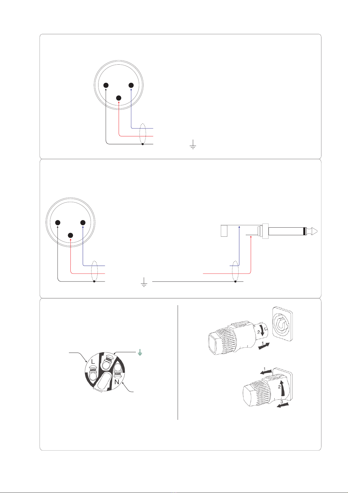
To meet the EMC requirements and minimize induced noise, use only shielded balanced cables with
properly connected plugs for all signal and shield terminals.
Note that restrictions may be applied by local authorities for temporary or fix installations in relation
to harmonics and voltage fluctuations (flicker), and to specific EMC emission-immunity issues.
Note that, a acoustical interference and malfunctions
may occur if the unit is operated in the immediate vicinity of
transmitters, wireless microphones, mobile
phones, etc.). Damage to the unit is unlikely, but cannot be excluded.
When stacking loudspeakers or setting up loudspeaker stands, make sure they are standing on a firm
and flat surface. Especially if you place loudspeakers on top of one another, unwanted movements
may occur due to sound vibrations, wind, etc. Use straps to secure them against dangerous
movements. Improper stacking could result in loudspeakers falling and causing injury.
MB 12.1, MB12.2W and MB 8.1 (this one provided with U bracket adaptor) can be mounted on
loudspeaker stand (35 mm diameter). Please refer to stand documentation for detailed instructions.
Improper installation or usage could result in the loudspeaker falling and causing injury.
MB 15.2, MB MAV-2W, MB 12.0 and MB 18.0 are not intended for use on loudspeaker stand.
MB 12.0 and MB 18.0, using a proper stand, can support MB 8.1, MB 12.1 or MB12.2W.
MB MAV-2W, MB12.0 and MB18.0 are only intended for use on the floor.
Whether MB systems are suspended or not, adequate grade (at least 8.8) M10 screws must be
completely screwed into all of the threded holes, since these are parts of internal bracing structure of
the cabinet. This is also important to assure the proper acoustical performance of the systems.
The handles on loudspeakers are for transportation. They are not designed for suspension or hanging.
Furthermore, as a basic safety notice, consider that this manual does not explain how to suspend
loudspeakers. To properly suspend any loudspeaker, a knowledge of structural engineering and
>
>
>
>
>
>
>
>
>
>
>
>
>
>
>
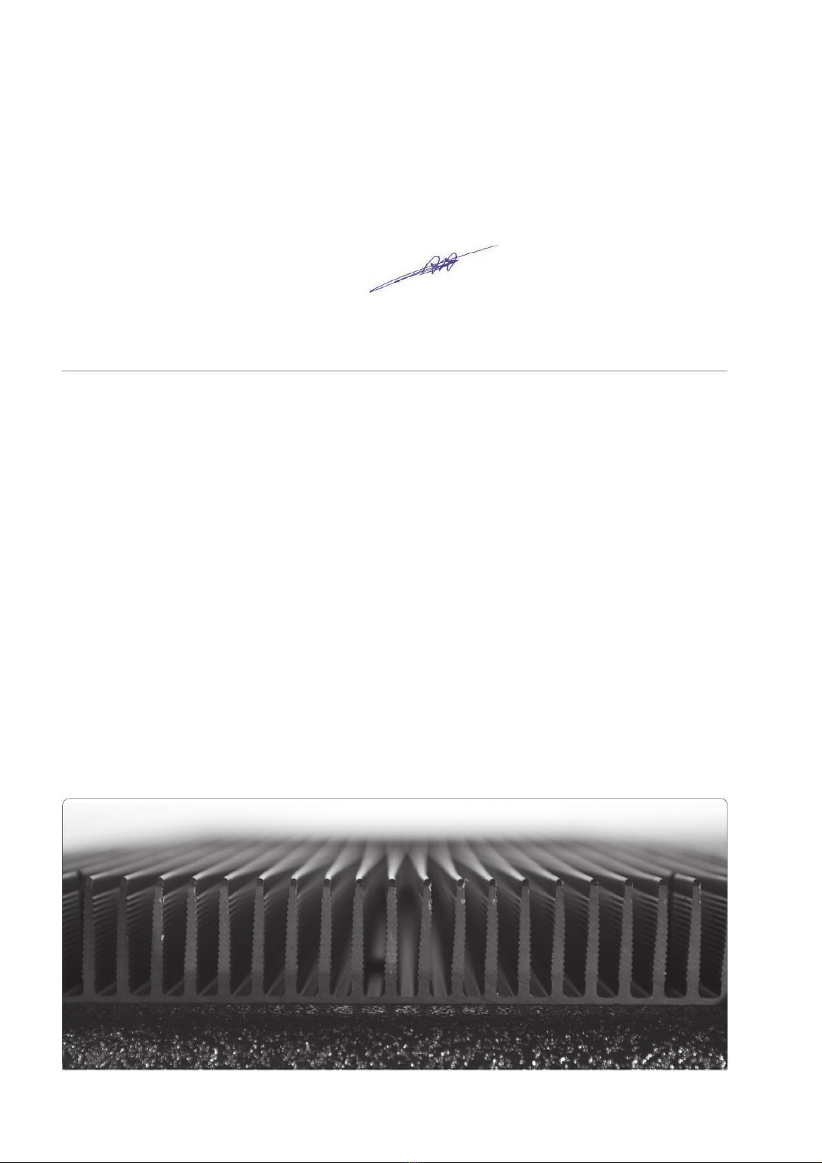
MB Loudspeakers are convection-cooled systems. Heatsink may become hot while the unit is
operating: use caution when approaching it.
In order to ensure adequate heat disposal the heatsink on the rear panel of the loudspeaker must not be
covered, not be under direct sunlight or spotlights, and adequate space for air ventilation must be
provided.
Do not operate at high volume levels o
s any equipment including signal processing,
a strong source of electromagnetic
radiation (e.g. power amplifiers, light dimmers, RF
For the same reason, please
ensure to keep signal cables as far as possible from mains cables.
Both models MB 12.1 and MB 15.2 can be flown, but never hang more than 3 loudspeakers under one
another. Specific MB suspension hardware must be used. Please contact your dealer and refer to MB
Suspension Hardware Manual for important operative and safety instructions.
MB 8.1 can be flown using the adequate U bracket adaptor and other specific hardware. Never link to
each-other more cabinets in a vertical line for safety reasons. Please contact your dealer and refer to
MB Suspension Hardware Manual for important operative and safety instructions.
For all suitable models, when hanging the loudspeaker, at least 2 hanging points must be used. An
additional and indipendent safety point for each loudspeaker is strongly recommended.
>
>
>
Mechanical Installation
Page 3

structural rigging is required. The improper installation of flying loudspeakers may result in bodily
injury or death. Always consult a licensed engineer to verify design and construction of any suspended
system, and to determine if rigging hardware, loudspeakers and their internal bracing parts are suitable
for your particular use. The owner and/or the user have responsibility to adhere to local regulations, to
evaluate reliability of any rigging system they use for their specific application and to determine
suitability of this product for any particular suspended usage. The manufacturer accepts no
responsibility for any accident, damage or failure of any rigged and suspended system.
In addition, please follow these safety steps:
Use only hardware specifically designed for rigging applications.
Consider pulling-angle factor at hanging points when planning rigging system.
Always use an independent safety suspension system as a backup for each suspended loudspeaker.
Do not use straps for lifting purposes.
Do not lift any loudspeaker system or other equipment over the head of people.
It is important to inspect both rigging hardware and rigging parts on loudspeakers, and replace worn
or damaged components immediately.
•
•
•
•
•
•
•When assembling flying hardware it is advisable to use thread-locking compound to eyebolts and
other bolts in order to avoid any possibility of loosening.
Page 4

Page 5
Wiring scheme for balanced Input/Parallel-Out XLR Audio Connectors (male / female)
Signal “ ”, out-of-phase or “COLD”
Signal “ ”, in-phase or “HOT”
Shield wire,
-
+
31
2
XLR Input
Connector
on
MB Loudspeaker
Signal out-of-phase connected to SLEEVE
Signal in-phase connected to TIP
Shield wire,
31
2
Not connected
Sleeve
Tip
Example wiring scheme when only unbalanced signal source is available
(different wiring scheme could be suggested depending on the specific situation)
Unbalanced signal source
Attached to this manual is part of manufacturer documentation for Neutrik PowerCon,
where you can find mechanical and electrical details how to assemble this connector.
Wiring scheme for
Neutrik PowerCon
(internal side view)
N(Neutral)
L(Live) (Ground)
PowerCon Insertion
Removal

Connectors Panel
Mains AC Input Supply Connector
Mains AC Output Supply Connector
Power LED
XLR Input Connectors
XLR Parallel Out Connectors
Operation Mode Switch
(C
.
onnections and Controls)
.
The connectors are on the rear or side panel of the Loudspeakers. The layout of connectors panel is
slightly different depending on MB Loudspeaker’s model. Please refer to specific layout for model(s)
you are using, which you can find on page 7.
MB Series Loudspeakers
This connector provides
MB Loudspeaker
accept input audio signal. Nominal input level is +4dBu. 12K
impedance electronically balanced. See Figure on page 5 for wiring scheme.
SubWoofer models MB 12.0 and MB 18.0 are provided with stereo input (Left and Right). Signals are
internally mixed to mono. This is usefull to setup systems consisting of stereo Full Range section and
mono SubWoofer section.
Note that Parallel Out (Left and Right) provides anyway Full Range stereo signal to drive other
systems.
When only one input is used on SubWoofer (e.g. Left input), then connecting Parallel Out Left to Right
Input drives +6dB signal into the SubWoofer. In general it is always recommended to drive both Left
and Right inputs on MB SubWoofers with identical signals, instead of driving one single input with
+6dB higher signal.
are
This switch configures internal processor to drive the system in mode or mode
().
In Full Range mode internal processor provides extended low frequency responce within the widest
Models MB 8.1, MB 12.1, MB 15.2, MB 12.2W, MB MAV-2W
W
Full-Range Crossover
HP
[1]
[2]
[3]
[4]
[5]
[6]
use a PowerCon 3-pole AC
mains connector for their power inlet (see Figure on page 5). It is important to determine and use
adequate wire gauge for mains cable considering the voltage drop that occurs across the cable’s
resistance. This is a function of the gauge and the length of the conductors, the current drawn by the load
and the startingAC mains voltage.
Internal fuse is provided on mains circuit, which will only blow in the event of major fault condition. In
case you suspect it is blown, refer to your dealer for service arrangement. Do not try to operate the unit.
Grounding-Shielding circuit is organized in the way that signal ground (XRL Pin1) and mains ground
are permanently connected together at one single point (internally). This reduces the risk of hum due to
ground loops when balanced audio equipments are properly connected in a chain.
output for mains line to link
other loudspeakers. The number of loudspeakers linked to each other must not exceed the main line
current capcity, and cable used should have adequate cross section. Anyway the total current of the
chain, including all systems connected, must not exceed the current rate of a single PowerCon (20A
maximum).
intended for the purpose of daisy-chaining multiple powered
Loudspeakers together on a common signal feed. Input and Parallel Out connectors are hard-wired in
parallel. Take care to check that the signal source is capable of driving the total impedance resulting
when paralleling the group of powered loudspeakers. As a practical rule use the following formula for
MB Loudspeakers:
12.000 [ ]
Maximum number of parallel Powered MB Loudspeakers = (Source Impedance [ ] x 10)
W
W
(blue) lights when is connected to mains supply and internal DC is
available.
Page 6

6
2
451
3
6
2
45
451
3
MB 8.1, MB 12.1, MB 15.2, MB 12.2W, MB MAV-2W Connectors Panel (example for MB 12.2W)
Page 7
MB 18.0, MB 12.0 Connectors Panel (example for MB 12.0)

Safe dynamic range.
In HP mode internal processor provides HP crossover function based on
acoustical responce. This perfectly matches the proper MB SubWoofer model.
This switch configures internal processor to drive SubWoofer in mode based on
acoustical responce at or .
The choice of Crossover Frequency depends on which MB Full Range model is used in combination
with MB 18.0 or MB 12.
The following table provides a general guideline how to combine Full Range and Subwoofer
models:
MB 8.1 (HP mode) - MB12.0 (100Hz mode): crossover frequency 100Hz.
MB 12.1 (HP mode) - MB 18.0 (100Hz mode): crossover frequency 100Hz.
MB 15.2 (HP mode) - MB 18.0 (80Hz mode): crossover frequency 80Hz.
Full Range mode should be chosen when
Loudspeakers (Full Range section) are used without SubWoofer. However HP mode may be also useful
as System-LowCut in specific situations. This results in acoustical responce shaped as
4th-order HP filter tunded at stated frequency (100Hz or 80Hz, depending on the model). On the other
side Full Range mode could be usefully operated by experienced engineers even when SubWoofer is
used, especially on MB 15.2, after phase relations amoung the different sources has been properly
analysed and tuned.
Follow these steps:
Make sure that all mains cables are disconnected in the reinforcement system.
Connect all audio cables respecting wiring schemes provided for operated equipment.
Provide proper configuration for Operation Mode Switches on all of Loudspeakers.
Switch on first other units (mixer, outboard effects, etc), then connect MB Loudspeakers to mains,
otherwise cracking noise could be expected which could potentially damage Loudspeakers.
After 5 seconds mute, the system is ready to work
Switch off sequence has to be reversed: first MB Loudspekaer, then other units.
For most applications driving MB SubWoofers and MB Loudspeakers (Full Range section) with the
same signal provides adequate balance. Driving SubWoofers with two input signals (Left and Right
inputs) increases the level (up to +6dB when signals are identical and in-phase). When a specific
different balance is needed, then an external level control is advised (e.g. Mono or Matrix output from
FOH EQ or Mixing Consolle).
l. In
this situation additional loudspeaker systems should be used, to provide the desired SPL.
Model MB 18.0 and MB 12.0
Crossover
100Hz 80Hz
-
Linkwitz-Riley 4th-order
Linkwitz-
Riley 4th-order
Linkwitz-Riley
Make sure that no audio signal (or very low level) is at Loudspeakers input, to avoid transients or
unexpected loud sound.
Each transducer inside MB Loudspeakers is provided with independent time-shaped limiter system
that reduces the risk of possible failures due to driver over-excursion and voice coil over-temperature.
This is achieved at the cost of minimum audible dynamics compression.
However a continuously increasing input level has to be avoided, as considerable and audible loss of
dynamics may be expected. In this situation although protected by the limiter, the components
experience a considerable loading (due to reduced crest factor of compressed audio program) which
can significantly shorten their lifespan.
The sound engineer should recognize, when input level is in the mentioned range or higher, that the
audio program from the loudspeaker is highly compressed and turn down the level of input signa
>
>
>
>
>
>
>
>
>
Operation Mode Switch (General Consideration).
Operating Sequence
Important Operating Notes
Page 8

>
>
>
>
>
>
MB Loudspeakers are designed for audio applications. Full range audio program signal is expected to
be used as input. Although time-shaped limiter systems are implemented, using high energy band-
limited signal, or exteme equalization (boost) on a full range signal may damage this equipment.
Overload and clipping must be avoided inside all of the equipments in the audio signal chain, since
there is no way to prevent distorted sound or possible damage to the loudspeakers when audio signal
at their input is already distorted.
are designed to be used within ambient temperature range 0°C - 45°C. Higher or
lower temperatures could cause the system to shutdown or result in components failure. Take care to
avoid direct intense sunlight on heatsink. This could raise the temperature of heatsink and force the
amplifiers to protection-mode to avoid permanent damage.
If MB Loudspeakers are used in horizontal position, cooling efficiency of the heatsink is reduced. In
this situation take care to evaluate ambient temperature and SPL level you need, to predict if the
margin is still reasonable before thermal
In order to avoid possible dangerous short circuits when touching other equipments or cables, please
consider that connectors panel and heatsink are at Ground level.
Visit the web site www.mbaudiosystems.com for more information about MB Audiosystems arrays
configuration, performance and fine tuning. Refer to
Please do not hesitate to contact your dealer if you have any doubt or question about MB Series
installation, specs or operations.
The information presented in this manual is, to the best of our knowledge, correct. The manufacturer
will however not be held responsible for the consequences of any error or omission.
Rights for names and trade-marks quoted in this manual belong to respective owners.
Digital converting/processing time inside MB Loudspeakers results in 1,5ms (milliseconds) delay for
all of MB models, referred to input signal. Use of different loudspeaker systems (provided with
analogue, digital, or no processing) in combination with MB Loudspeakers should be carefully
evaluated. Delay difference should be compensated, if needed, to avoid destructive acoustical
interference.
Thermal protection operates when heatsink (internal) temperature reaches 85°C. As a consequence
the amplifiers will shutdown, and automatically restore when the temperature decreases below
mentioned threshold.
MB Loudspeakers
protection will shutdown the amplifiers.
In case one of the protection systems is engaged and doesn’t automatically restore when the cause is
removed, you can restore it manually disconnecting mains and reconnecting after 15 seconds.
MB Suspension Hardware Manual for important
information about suspension hardware setup, and follow all safety recommendations.
In keeping with a
policy of continued improvement, the manufacturer reserves the right to alter specifications without
further notice.
>
>
Page 9

Page 10
Cestatement of conformity
Warranty Statement
The manufacturer HOF Sales B.V. - The Netherlands, declares
that the products MB8.1, MB12.1, MB15.2, MB12.0, MB18.0 , MB 12.2W, MB MAV-2W, to which
this statement refers, conforms to the following standards or other type of regulatory documents: EN
60065, EN 55103-1, EN 55103-2 with reference to EU directives 73/23 and 89/336.
Haren, 01/03/2009
Responsible for HOF Sales B.V.
Auke Meijer
The form of this statement conforms to EN 45014 specifications.
marking is on the rear panel of the product, in the area close to power supply connector.
HOF Sales B.V. - The Netherlands.
ce
- Felland Noord, 3 - 9753 TB - Haren
Manufacturer: - Felland Noord, 3 - 9753 TB - Haren
Products have a warranty period of 36 months, starting from delivery date. Electronic components
(analogue modules, semiconductors, capacitors, etc.), digital modules and acoustical transducers are
excluded from this warranty; general manufacturer conditions and warranty policy apply for these
components. Warranty only applies when the final payment has been received by the dealer or the
manufacturer. Warranty will be valid only if this statement, together with the original invoice, will be
shown to an authorized service centre or to the manufacturer. If the product does fail during the
warranty period, which can be related to components or mounting defects to be decided by the
authorized service centre or manufacturer, all costs regarding labour and replacement parts will be at
manufacturer expense. Warranty does not apply if the serial number (S.N.) is deleted or modified on the
product. Warranty is not valid if the product has been damaged by negligence or incompetence of the
customer or user, for accident, or if all indications, use-limits and safety warnings explaned in the user
manual (provided with the product) have not been respected. Warranty does not apply if any
unauthorized modification has been made to the product, without prior written notice from the
manufacturer. The manufacturer is not held responsible for any inconvenience caused during the time
the product cannot be used. No refund will be made for cost incurred by repairs and/or replacement
parts made by non authorized service centres. In all cases the customer will send the product at own risk
and costs to service centre or manufacturer. Only warranty stated by the manufacturer apply in all
circumstances.

Performance & Physical Data MB 8.1 MB 12.1 MB 15.2 MB12.2W MB 12.0 MB18.0 MB MAV-2W
Notes
(1)
(2)
(3)
(4)
(5)
(6)
Frequency Response 66Hz - 18KHz 54Hz - 18,5KHz 38Hz - 18,5KHz 65Hz - 18KHz 42Hz - 90Hz 32Hz - 90Hz 50Hz - 18,5KHz
Operating Frequency Range 59Hz - 19KHz 48Hz - 19,5KHz 33Hz - 19,5KHz 60Hz - 18KHz 35Hz - 100Hz 29Hz - 100Hz 47Hz - 19KHz
Maximum SPL 127dB SPL 131,6dB SPL 134,6dB SPL 130,2dB SPL 127,8dB SPL 134,3dB SPL 136,9dB SPL
Coverage Angle 100° (conical) 85° x 40° 65° x 40° 80° (conical) Omni Omni 75° x 55°
Coverage Angle Range 1,3 - 14KHz 1,1 - 13KHz. 0,7 - 13KHz 1,5 - 14KHz 35 - 90Hz 29 - 80Hz 950Hz - 13KHz
Transducers LF
Transducers HF 1-in exit, coaxial 1-in exit driver 2-in exit driver 2-in exit driver - - - - 1,4-in exit driver
1,7-in diaphragm 1,7-in diaphragm 3-in diaphragm 3-in diaphragm 3-in diaphragm
horn loading CD horn loading CD horn loading horn loading CD horn loading
Balanced Input Section Sensitivity +4dBu
Connectors Female XLR, Male XLR loop out
Input Impedance 12K balanced
Amplifiers Type (convection cooled) High Efficiency High Efficiency High Efficiency High Efficiency High Efficiency High Efficiency High Efficiency
Digital Amplifier Digital Amplifier Digital Amplifier Digital Amplifier Digital Amplifier Digital Amplifier Digital Amplifier
Burst capability 2 x 300W 2 x 610W 3 x 610W 2 x 610W 880W 1860W 2 x 1200W
THD, DIM, SMPTE: < 0,05%
Protections Over-temperature power limiting, Thermal shutdown, Short-circuit/Overload output protection, Soft Clip limiter
DSP on board 48KHz AD/DA, 24bit. Signal routing, crossovers, system-Eq, offset delay, time-shaped limiters
Mains Connector PowerCon AC-input connector, link PowerCon Out
Mains AC Power Nominal 230VAC(195-240) - 50Hz
Current Requirement 2A 3A 4A 3A 3A 4A 4A
Dimensions (HxWxD)cm 34,5 x 26,5 x 26,5 55x36,5x40 73x52x43 41x51x28 44x36x48 85,5x50x52 43,5x74x31
Weight 11 Kg 25 Kg 45,3Kg 26 Kg 24,5Kg 45 Kg 25,3 Kg
Cabinet baltic birch multiply 12mm 18mm 18mm 18mm 18mm 18mm 18mm
Finish Black scratch resistant waterborne coating system.
Protection Grill Perforated steel grill, powder coated.
35mm pole mount
Hanging Points
Frequency Response ( 3dB) measured on-axis in half-space loading condition, 1/36 octave frequency resolution. Half space condition occurs when floor, rear or side walls are close to
loudspeaker, and affect low frequencies loading.
Range limits stated at - 6dB.
Maximum Full Range SPL measured in half-space loading condition, referred to 1m measurement distance, with pink noise (6dB crest factor).
- 6dB points.
Amplifier capability with pink noise (6dB crest factor).
Performance Data measured with 230VAC.
(1)
(2)
(3)
(4)
(5)
(6)
8-in V-Reflex 12-in optimally 15-in V-Reflex 12-in optimally 12-in optimally 18-in optimally 15-in optimally
Technology provides vented cone driver Technology provides vented cone driver vented cone driver vented cone driver vented cone driver
maximum LF output maximum LF output
Full Range / High Pass (100Hz LR24) FR / HP (80Hz LR24) FR/HP (100Hz LR24) 80Hz / 100Hz LP (LR24) FR / HP (90Hz LR24)
- - On bottom panel - - On bottom panel On top panel - -
2 x M10, on top 5 x M10, on top, 5 x M10, on top, -- -- -- --
and bottom panel b b
W
+
Crossover Frequency 1750Hz nominal 1350Hz nominal 650Hz nominal 850Hz nominal 100Hz nominal 100Hz nominal 860Hz nominal
Operation Mode Switch
On top panel
ottom and rear panel ottom and rear panel
AUDIOSYSTEMS
Product Range
Page 11

This manual suits for next models
7
Table of contents