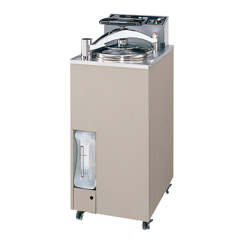
Sanyo MDF-U730 User manual

SANYO
Manual
Biomedical
freezer
SANYO
Electric
Biomedical
CO.,
Ltd
MDF-U730
FILE
NO.
SM9910044

EFFECTIVE
MODELS
This
service
manual
is
effective
following
models.
Model
Model
code
Voltage/Hz
MDF-U730
115V
823-178-51
60Hz

Contents
Features:
Specification
Performance
specification
-
Specification
of
sensor
-
Parts
specification
Dimensions
Wiring
diagram
Refrigeration
circuit
principle
diagram
-
Refrigeration
circuit
welding
points
-
Data
on
cooling
capacity
-
Instruction
manual
-
Extract
of
Instruction
Manual
-
Precautions
For
Safe
Operation
-
Test
data
-
Trouble
shooting
ONO
a
R
O
N
=
11
-
12
-
14
-
31
-
33

Features
HFC
refrigerant
Refrigerant
circuit
contains
HFC
refrigerant
that
effect
to
environment
little.
Latest
cooling
system
reduces
negative
factor
to
global
environment.
With
ambient
temperature
shown
at
35°C,
while
temperature
inside
chamber
maintains
-35°C.
PCM
structure
PCM
structure
reduces
amount
of
organic
solvent.
Internal
cooled
air
forced
circulation
Internal
cooled
air
forced
circulation
by
internal
fan
motor
is
adopted
to
ensure
the
uniform
internal
temperature.
Digital
display
and
digital
setting
Digital
display
indicates
the
internal
temperature.
Thermister
sensor
is
adopted
as
a
temperature
sensor
because
it
has
high
stability
of
accuracy.
Microcomputer
controls
internal
temperature
by
receiving
signal
from
thermister
sensors.
The
unit
has
various
kinds
of
safety
functions,
such
as
high
temperature
alarm.
Alarm
is
shown
by
blinking
LED
lamp
and
buzzer
sounds.
The
unit
also
has
remote
alarm
contact.
Auto
defrosting
function
Defrost
is
performed
by
special
heater
installed
in
cooling
unit
for
a
short
time.
The
unit
also
has
manual
defrosting
function
to
be
able
to
defrost
at
regular
timing.

Specification
MDF-U730
Items
Specification
Model
description
Biomedical
freezer
Model
Number
MDF-U730
Outer
dimension
(Max)
W
770
x
D
830
x
H
1955
mm
Inner
dimension
W
650
x
D
710
x
H
1370
mm
Effective
chamber
capacity
632
liters.
22.4cu.ft
Cooling
performance
-30°C
at
1/2
height
of
the
chamber
(
AT
:
35°C,
No
load
)
Exterior
cabinet
Zinc
galvanized
steel
w/powder
polyester
coating
(new
bio-gray)
Interior
cabinet
Pre-coated
steel
(white)
Insulation
Rigid
polyurethane
foam
Foam:
R-141b
Door
Zinc
galvanized
steel
w/powder
polyester
coating
(new
bio-gray)
Door
lock
1
pcs
Compressor
Hermetic
rotary
type
(
300W
)
Refrigerant
R-404A
(HFC
refrigerant)
Refrigerator
oil
E-68NT1
—
ME
te
MA
VATANE
.
Condenser
Skin
type
a
'
ー
Shelf
Hard
steel
wire
PE
coating.
Max
load
:
50kg/shelf
Accessories
4
pcs
(W626mmxD620mm)
Others
Key
1
set
,2
large
&
2
small nylon
clips
Caster
4рсз.
(Front
&
rear
movement
wheels)
Leveling
legs
2
pes
in
front
side.
Access
hole
Inner
diameter
30mm.
1
places
in
left
side
of
frame
and
1
places
on
top
of
the
unit.
Option
„Automatic
recorder:
MTR-G85G,
fixture
MPR-S7
Automatic
recorder:
MTR-4014LH,
fixture
MPR-S30
Power
supply
Single
phase,
local
voltage
Weights
150
kg

Items
Specification
Internal
temp.control
range
|
-20°C
—
-30°C(AT
:
5°C
~
35°C,
RH80%less)
Settable
Range
Temp.
set
range
:
-15°C
—
-35°C
Temperature
sensor
Thermistor
Temperature
display
LED
digital
display
(red
colored)
by
1°C.
Range
:
-40°C
—
0°C
In
case
Internal
Temp
higher/lower
than
set
temp.
10degrees,
High/Low
ALARM
lamp
brinks
and
buzzer
sounds
intermittently
(about
Temperature
15
min.
delay)
Remote
alarm
contact:
turns
ON
with
buzzer
sounds
Alarm
ALARM
lamp
brinks,
buzzer
sounds
intermittently,
remote
Power
failure
alarm
contact
turns
ON
and
display
is
extinguished.
Remote
alarm
terminal
3P:
contact
capacity
DC30v,
2A,
Remote
N.O.
-COM.
(During
temperature
alarm,
power
failure
alarm,
alarm
test:
ON)
ALARM
lamp
BUZZER:
Buzzer
key
ALARM
TEST:
Alarm
test
key
Control
panel
SET:
To
switch
the
SV
and
PV
»»
:
To
shift
the
set
digit
4
:
To
change
the
SV
DEF:
Defrost
key
Press
>>
key
for
five
seconds
ME
AE
lm
Lo0:
Unlock
Lo1:
Lock
“When
temperature
sensor
is
in
fault,
In
case
sensor
shorted,
error
code
E01/HI
are
displayed.
In
case
sensor
opened,
error
code
E01/LO
are
displayed.
“When
defrost
sensor
is
in
fault,
Self
diagnosis
functi
。
9
Unetion
In
case
sensor
shorted,
error
code
E02/
internal
temp.
are
displayed.
In
case
sensor
opened,
error
code
E02/
internal
temp.
are
displayed
Power
switch
Side
on
rear
box
Battery
switch
Behind
on
front
cover
Power
supply
Local
voltage
Performance
specification
115V/60hz
110V/60hz
Cooling
capacity
-30°C
Temperature
control
range
-20°C
~
30°C
Motor
rated
power
consumption
300W
Motor
rated
current
2.9
A
-3-

Specification
of
sensor
The
following
show
temperature
and
resistance
characteristics
on
thermistor
sensor
for
internal
temperature
control
(type
:
TIS-202PH-037)
and
defrosting
(type
:
TIS-202PH-045)
Temperature
|
Resistance
|
Temperature]
Resistance
|
Temperatur
|
Resistance
(°C)
(ΚΩ)
(°C
)
(ΚΩ)
е
(°С)
(ΚΩ)
-
40
59.387
-
25
23.439
-
10
10.216
-
39
55.627
-
24
22.112
-5
7.898
-
38
52.131
-
23
20.869
0
6.160
-
37
48.881
-
22
19.705
5
4.846
-
36
45.856
-
21
18.614
10
3.842
-
35
43.039
-
20
17.590
15
3.070
-
34
40.415
-
19
16.630
20
2.471
-
33
37.970
-
18
15.728
25
2.003
-
32
35.690
-17
14.882
30
1.634
-
31
33.563
-
16
14.087
35
1.342
-
30
31577
-16
13.339
40
1.109
-
29
29.723
-
14
12.636
45
0.921
-
28
27.990
-13
11.975
50
-27
26.371
-
12
11.353
-
26
24.856
-
11
‚
10.767

Parts
specification
|
115V6ohz
|
|
|
Compressor
:
Hermetic
rotary
type
Main
winding
:
Between
C-R
S
Aux
.
winding
:
Between
C-S
C
(at
25°C)
R
Type
80778022
Output
400W
Resistance
(main
winding)|
1.820
Resistance
(Aux.
winding)
5.430
Over
load
relay
Type
P22MUF
Operating
130+10°C
temperature
69+10°C
Closing
temperature
5
~
15sec
Short
time
trip
Starting
capacitor
:
To
make
compressor
start
easily
Rating
100uF
160VAC
Running
capacitor
Rating
20uF
220VAC
Starting
relay
:
To
supp
ly
both
winding
with
the
power
to
start
up
compressor
Type
AMVL-180A
Operating
voltage
108
~111V
Recovering
voltage
30
~
75V
Cooling
fan
motor
:
To
circulate
internal
air
Type
FL2-
C011BMPK
Rating
110V,1.5W
Defrost
heater
:
To
defrost
on
cooling
unit
during
defrosting
Resistance
12.40x2
Output
165Wx2
Drain
pan
heater
:
To
heat
the
drain
pan
during
defrosting
Resistance
1770
Output
75W

Dimensions
0501
820-1
MU
-一
一
一
一
_—_
a,
o
—
0681-
—0€

Wiring
diagram
SON
РОВ
|
e
sese
DOOR
SWITCH
POWER
CORD
115V-60Hz
LOAD LINE
гиг
æ
| |
e
|
i
|
| |
| |
öğ
| |
|BLIR
ECTS
|
| | |
i
CN3
0
Ci
|
| i |
|
|
SWITCH
BATTERY
|
| | |
| | |
|
Mo
| | 1
|
i
DRAIN
PAN
HEATER
| |
||
1
"A
Am.
|
|
DEF,
HEATER
B
|
|
ta?
|
MN
lolo!
1
|
TEMP,
FUSE
|
DEF,
HEATER
A
|
7
DAY
RECORDER
Ri
a
BN
COMP.RELAY
|
| |
FA
MOTOR
A
|
|
©
|
|
ото
в
ーーーーーーーー
|
|
一
一
一
у
|
|
FA
BL
|
m
|
FA
Y
SOLENOID
VALVE
GE)
C
COMPRESSOR
|
7
3
|
STARTING
RELAY
LA
|
v
TA
"и
|
OVERLOAD
PROTECTOR
>
8
TR
la
全
一
RUNNING
CAPACITOR
|BL
—
|
0
FAN
MOTOR
|
YA
STARTING
CAPACITOR
|
|
В:
BLACK
R:
RED
|
BL:
BLUE
V:
VIOLET
GR:
GRAY
N:
WHITE
MDF-U730
CIRCUIT
DIAGRAM
ONE
때

Refrigeration
circuit
principle
diagram
MW
(On
unit
room
left
wall)
<
Rotary
compressor
Evaporator
NANA
Sub
cooler
Sub
cooler
(On
unit
room
right
wall)
Accumulator
Check
valve
Evaporator
Skin
condenser
Å
(On
the
cabinet
rear)
Capillary
tube
.
Solenoid
valve
Skin
condenser
(On
the
cabinet
left
side)
Frame
pipe
Skin
condenser
(On
the
cabinet
right
side)
Dry
core
X
1

Refrigeration
circuit
Welding
points
Right
side
cabinet
condenser
(in
the
cabinet)
Condenser
Rear
(in
the
cabinet)
Accumula
Pre-condenser
right
(In
the
cabinet)
Frame
pipe
(In
the
cabinet
)
…
Check
valve
Pre-condense:
left
>
Left
side
cabine
Evaporating
pipe
condenser
(Rear
of
frame)
个
(in
the
cabinet)
Se
Fap
eg
e
©-
Capillary
tube
EA
<
FBI
=
4
Gi
eces
in
ust
F
SEB
r,
DE
se
—
©
-A
|
EA
EB1
EL
Evaporator
assy
(in
the
chamber)

Data
on
cooling
capacity
Temperature('C)
50.0
30.0
30,0
50.0
N
N
The
Interal
ifemperaturd
Of
Unit
v
N
OR
Oh
lh
.
개
개
새
Time
scale
-10-
5h

Instruction
Manual
m
This
section
is
extracted
and
printed
Instruction
Manual.
m
If
you
find
out
"
Refer
to
page
ee
"
in
them,
that
page
means
not
page
in
service
manual
but
page
in
the
lower
corner
of
each
page
in
the
extract
from
user's
manual.
That
page
number
is
not
corresponded
with
serial
number
in
Service
manual.
-11-

Extract
of
Instruction
manual
PRECAUTIONS
FOR
SAFTY
OPERATION
You
must
conform
to
this
manual
after
reading
throughout
well,
because
this
manual
contains
many
important
items
for
safty
Items
are
described
so
that
you can
use
this
unit
safety
and
properly,
and
so that
you
can
take
precautions
to
prevent
possible
injury
and
damage
to
you
and
other
people.
They
are
distinguished
[WARNING]
from
[CAUTION]
by
its
contents.
Be
sure
to
observe
those
contents
because
they
contain
many
important
items
for
safety
operation.
Indication
and
meaning
are
as
follows.
[El
WARNING
This
contents
means
that
it
is
possible
to
result
in
final
injury
or
serious
injury
to
human
beings.
Я
[CAUTION
This
contents
means
that
it
is
possible
to
result
in
injury
to
human
beings
and
damage
to
thing.
Mark
shows
;
ES 回
mark
means
caution.
O
回
mark
means
prohibition.
回
Gi
mark
means
an
instruction.
Da

<
Label
on the
unit
>
This
mark
is
labeled
on
the
cover
in
which
the
electrical
components
of
high
voltage
are
enclosed
to
prevent
the
electric
shock.
The
cover
should
be
removed
by
a
qualified
engineer
or
a
service
personnel
only.
Be
sure
t
any
time.
o
keep
this
manual
in
the
place
accessible
by
users
at
any
«19

PRECAUTIONS
FOR
SAFE
OPERATION
/NWARNING
Do
not
use
the
unit
outdoors.
Current
leakage
or
electric
shock
may
result
if
the
unit
is
exposed
to
rain
water.
Only
qualified
engineers
or
service
personnel
should
install
the
unit.
The
installation
by
unqualified
personnel
may
cause
electric
shock
or
fire.
Be
sure
to
install
the
unit
on
a
sturdy
floor.
_
If
the
floor
is
not
strong
enough
or
the
installation
site
is
not
adequate,
this
may
result
in
injury
from
the
unit
falling
or
tipping
over.
Never
install
the
unit
in
a
humid
place
or
a
place
where
it
is
likely
to
be
splashed
by
water.
Deterioration
of
the
insulation
may
result
which
could
cause
current
leakage
or
electric
shock.
Never
insiall
the
unit
in
a
flammable
or
volatile
location.
This
may
cause
explosion
or
fire.
Never
install
the
unit
where
acid
or
corrosive
gases
are
present
as
current
leakage
or
electric
shock
may
result
due
to
corrosion.
Make
sure
a
dedicated
power
source
is
used
as
indicated
on the
rating
label
attached
to
the
unit.
Make
sure
to
remove
dust
from
the
power
supply
plug
before
inserting
in
a
power
source.
A
dusty
plug
or
improper
insertion
may
pose
a
hazard.
Use
a
power
supply
outlet
with
ground
(earth)
to
prevent
electric
shock.
If
the
power
supply
outlet
is
not
grounded,
it
will
be
necessary
to
install
a
ground
by
qualified
engineers.
Never
ground
the
unit
through
a
gas
pipe,
water
main,
telephone
line
or
lightning
rod.
-
Such
grounding
may
cause
electric
shock
in
the
case
of
an
incomplete
circuit.
Do
not
insert
metal
objects
such
as
a
pin
or
a
wire
into
any
vent,
gap
or
any
outlet
for
inner
air
circulation.
This
may
cause
electric
shock
or
injury by
accidental
contact
with
moving
parts.
Never
store
volatile
or
flammable
substances
in
this
unit.
This
may
cause
explosion
or
fire.
Never
store
corrosive
substances
in
this
unit.
This
may
lead
to
damage
to
the
inner
components
or
electric
parts.
If
this
unit
is
to
be
used
for
storing
poisons,
radioactive
material
or
other
harmful
products,
ensure
that
it
is
in
a
safe
area.
Failure
to
do
so
may
lead
to
an
adverse
effect
on the
health
of
personnel
in
the
area
and
the
local
environment.
In
this
case,
a
request
for
repair
or
maintenance
will
necessitate
a
safety
check
sheet
for
maintenance
personnel.
9.000
0909606000066
0
-14-

PRECAUTIONS
FOR
SAFE
OPERATION
A ©
O
è
©
© ©
人
WARNING
Always
disconnect
the
power
supply
to
the
unit
prior
to
any
repair
or
maintenance
of
the
unit
in
order
to
prevent
electric
shock
or
injury.
Ensure
you
do
not
inhale
or
consume
medication
or
aerosols
from
around
the
unit
at
the
time
of
maintenance.
These
may
be
harmful
to
your
health.
Never
splash
water
directly
onto
the
unit
as
this
may
cause
electric
shock
or
short
circuit.
Never
disassemble,
repair,
or
modify
the
unit
yourself.
Any
such
work
carried
out
by
an
unauthorized
person
may
result
in
fire
or
injury
due
to
a
malfunction.
Disconnect
the
power
supply
plug
if
there
is
something
wrong
with
the
unit.
Continued
abnormal
operation
may
cause
electric
shock
or
fire.
If
the
unit
is
to
be
stored
unused
in
an
unsupervised
area
for
an
extended
period,
ensure
that
children
do
not
have
access
and
that
doors
cannot
be
closed
completely.
The
disposal
of
the
unit
should
be
accomplished
by
appropriate
personnel.
Always
remove
doors
to
prevent
accidents
such
as
suffocation.
Make
sure
to
prepare
a
safety
check
sheet
when
you
request
any
repair
or
maintenance
for
the
safety
of
service
personnel.
=
B

PRECAUTIONS
FOR
SAFE
OPERATION
O
©
4000000086
20900
/\CAUTION
Select
a
level
and
sturdy
floor
for
installation.
This
precaution
will
prevent
the
unit
from
tipping.
Improper
installation
may
result
in
water
spillage
or
injury
from
the
unit
tipping
over.
Connect
the
unit
to
a
power
source
as
indicated
on
the
rating
label
attached
to
the
unit.
Use
of
any
other
voltage
or
frequency
other
than
that
on
the
rating
label
may
cause
fire
or
electric
shock.
Fix
the
shelves
securely.
Incomplete
installation
may
cause
injury
or
damage.
When
removing
the
plug
from
the
power
supply
outlet, grip the
power
supply
plug,
not
the
cord.
Pulling
the
cord
may
result
in
electric
shock
or
fire
by
short
circuit.
Never
damage
or
break
the
power
supply
plug
or
cord.
Do
not
use
the
supply
plug
if
its
cord
is
loose.
This
may
cause
fire
or
electric
shock.
Do
not
touch
any
electrical
parts
such
as
the
power
supply
plug
or
any
switches
with
a
wet
hand.
This
may
cause
electric
shock.
Do
not
climb
onto
the
unit
or
do
not
put
articles
on
the
unit.
This
may
cause
injury
by
tipping
or
damage
to
the
unit.
Do
not
store
bottle
or
cans
in
the
freezer.
This
may
cause
injury by
broken
of
containers
due
to
the
frozen.
Do
not
touch
any
stock
(especially
metal
objects)
in
the
freezer
with
a
wet
hand.
This
may
cause
frostbite.
Always
hold
the
handle
when
closing
the
door.
This
will
reduce
the
likelihood
of
a
trapped
finger.
Do
not
lean
on
the
door.
This
may
cause
injury
if
the
unit
tips
over.
Always
disconnect
the
power
supply
plug
before
moving
the
unit.
Take
care
not
to
damage
the
power
cord.
A
damaged
cord
may
cause
electric
shock
or
fire.
Dispose
of
water
in
the
evaporation
tray
completely
prior
to
the
movement.
Spilled
water
or
splashed
water
may
cause
current
leakage
or
electric
shock.
Be
careful
not
to
tip
over
the
unit
during
movement
to
prevent
damage
or
injury.
Always
disconnect
the
power
plug
when
the
unit
is
not
used
for
long
periods.
Make
sure
to
check
the
setting
value
when
starting
up
the
operation
after
the
power
failure
or
power
off.
Achange
of
setting
value
may
cause
damage
to
contents.
Do
not
put
the
packing
plastic
bag
within
reach
of
children
as
suffocation
may
result.
-16-

CAUTIONS
FOR
USAGE
1.
If
the
unit
is
unplugged
or
the
power
to
the
unit
is
interrupted,
do
not
restart
the
unit
for
at
least
5
minutes.
This
protects
the
compressor.
2.
This
inner
cabinet
is
refrigerated
by
the
forced
circulation
of
cooled
air
inside
the
chamber.
Ensure
that
the
intake
and
exhaust
vents
are
not
blocked.
Adequate
space
should
be
provided
between
the
items
inside
the
unit
to
allow
air
circulation.
3.
Never
store
corrosive
materials
such
as
acid
or
alkali
unless
the
container
is
completely
sealed
up.
Corrosion
may
lead
to
failure
of
the
unit
in
time.
4.
Once
the
chamber
temperature
has
stabilized,
put
the
items
into
the
chamber
in
small
batches
to
minimize
the
temperature
increase.
5.
Fix
the
shelves
securely.
Place
items
on
the
shelves
and
leave
a
space
between
the
walls
of
the
cabinet
and
the
contents
to
allow
air
circulation.
Do
not
place items
on the
floor
of
the
chamber.
6.
Always
close
the
door
firmly.
The
door
check
lamp
is
lit
when
the
door
is
open.
The
alarm
buzzer
sounds
two
minutes
after
door
opening.
The
buzzer
can
be
canceled
automatically
when
the
door
is
closed.
7.
Always
open
and
close
the
door
gently.
Rough
operation
may
lead
fall
down
of
stocked
items,
incomplete
closing,
or
damage
of
door
gasket.
8.
Do
not
stock
articles
beyond
the
load
line.
Containers
outside
the
load
line
disturb
the
air
circulation
in
the
chamber
and
cause
poor
cooling.
9.
In
the
refrigerator
compartment,
put
the
items
on
the
shelves
and
do
not
contact
the
items
with
wall.
10.
If
an
instrument
requiring
a
power
source
is
to
be
placed
inside
the
cabinet,
the
cable
can
be
lead
through
the
access
port
on
the
right
side
and
top
of
the
cabinet.
After
using
of
the
port,
a
rubber
cap
and
insulation
should
be
replaced
to
seal
the
access
port.
Failure
to
do
this
can
affect
the
temperature
uniformity
inside
the
cabinet and
lead
to
condensation
on
the
outside
of
the
access
port.
11.
Do
not
clean
the
unit
with
scrubbing
brushes,
acid,
thinner,
solvents
powdered
soap,
cleanser
or
hot
water.
These
agents
can
scratch
the
paint
or
cause
it
to
peel.
Plastic
and
rubber
parts
can
be
easily
damaged
by
these
materials.
Especially
never
use
any
volatile
solvent
to
clean
the
plastic
or
rubber
parts.
When
a
neutral
dishwashing
detergent
is
used
to
clean
the
unit,
wipe
it
up
thoroughly
with
a
cloth
soaked
in
clean
water.
12.
If
condensation
forms
on
the
door
or
frame
surface,
wipe
it
off
with
a
dry
soft
cloth.
13.
The
heat
discharge
pipe
is
attached
inside
of
the
both
side
&
rear
frame.
The
frame
sometimes
hot
at
the
start-up
of
the
operation.
But
this
does
not
mean
malfunction.
-17-
Other manuals for MDF-U730
1
Table of contents
Other Sanyo Laboratory Equipment manuals