For KC standard only
A급기기(업무용방송통신기자재)
이기기는업무용(A급)전자파적합기기로서판매자
또는사용자는이점을주의하시기바라며,가정외의
지역에서사용하는것을목적으로합니다.
●I/O connector
Connection example
-Cable-
FZ-VP 2M / FZ-VP 5M / FZ-VPX 2M / FZ-VPX 5M
●Camera connector
Connection example
-Cable-
FZ-VS3 2M / FZ-VS3 3M / FZ-VS3 5M / FZ-VS3 10M
FZ-VSB3 2M / FZ-VSB3 3M / FZ-VSB3 5M / FZ-VSB3 10M
FZ-VSL3 2M / FZ-VSL3 3M / FZ-VSL3 5M / FZ-VSL3 10M
FZ-VSLB3 2M / FZ-VSLB3 3M / FZ-VSLB3 5M / FZ-VSLB3 10M
FZ-VS4 15M
FZ-VSL4 15M
-Camera-
FZ-SC / FZ-S
FZ-SFC / FZ-SF / FZ-SPC / FZ-SP
FZ-SHC / FZ-SH
FZ-SC2M / FZ-S2M
FZ-SC5M2 / FZ-S5M2
FZ-SQ010F / FZ-SQ050F / FZ-SQ100F / FZ-SQ100N
-Terminal connect -
FZ-VSJ
A1
A2
A3
A4
A5
A6
A7
A8
A9
A10
A11
A12
A13
A14
A15
A16
A17
A18
A19
A20
A21
A22
A23
A24
A25
B1
B2
B3
B4
B5
B6
B7
B8
B9
B10
B11
B12
B13
B14
B15
B16
B17
B18
B19
B20
B21
B22
B23
B24
B25
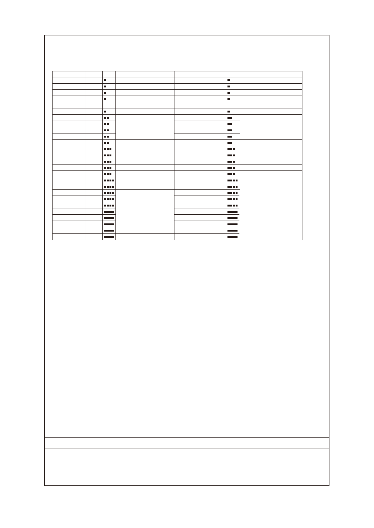
No. Wire color
Mark (red)
Function
Signal name
No.
COMIN
ENCTRIG_A1 (*2)
ENCTRIG_B1 (*2)
STEP1 (*2)/
ENCTRIG_Z1 (*2)
DSA1 (*2)
DI1
DI3
DI5
DI7
STGOUT1
STGOUT3
ERROR
COMOUT1
GATE1 (*2)
OR1 (*2)
READY1 (*2)
COMOUT2
DO1
DO3
DO5
DO7
DO9
DO11
DO13
COMOUT3
Orange
Gray
White
Yellow
Pink
Orange
Gray
White
Yellow
Pink
Orange
Gray
White
Yellow
Pink
Orange
Gray
White
Yellow
Pink
Orange
Gray
White
Yellow
Pink
Wire color
Mark (blk)
Function
Signal name
Orange
Gray
White
Yellow
Pink
Orange
Gray
White
Yellow
Pink
Orange
Gray
White
Yellow
Pink
Orange
Gray
White
Yellow
Pink
Orange
Gray
White
Yellow
Pink
RESET
DSA0
DI0
DI2
DI4
DI6
STGOUT0
STGOUT2
RUN/BUSY1 (*2)
BUSY0
GATE0
OR0
READY0
DO0
DO2
DO4
DO6
DO8
DO10
DO12
DO14
DO15
Sensor Controller restart
Data send request signal
Command inputs
Strobe trigger output (*1)
Strobe trigger output (*1)
*3
ON during processing
ON for the set output time
Overall judgment result
ON when image input is allowed
Data output
Common for input signals
Encoder trigger input (Phase A)
Encoder trigger input (Phase B)
Measurement trigger input/
Encoder trigger input (Phase Z)
Data send request signal
Command inputs
Strobe trigger output (*1)
Strobe trigger output (*1)
ON when there is an error.
Common for output signals
ON for the set output time
Overall judgment result
ON when image input is allowed
Common for output signals
Data output
Common for output signals
•Handling the output common terminals
COMOUT1: STGOUT0 to 3, RUN/BUSY1, ERROR, BUSY0, OR0 to 1, GATE0 to 1 COMOUT2: READY0 to 1, DO0 to 7 COMOUT3: DO8 to 15
*1 This is a signal that is used when the strobe device is connected to the Sensor Controller.
*2 This signal is only available in the Random trigger mode.
*3 ON while the layout turned on output setting is displayed / ON during processing
ENCTRIG_A0
ENCTRIG_B0
STEP0/
ENCTRIG_Z0
Encoder trigger input(Phase A)
Encoder trigger input(Phase B)
Measurement trigger input/Encoder
trigger input(Phase Z)


