MBT Vaca Shape User manual

1
User Manual

2
Content
Chapter 1 Equipment Parts .................................................................................................1
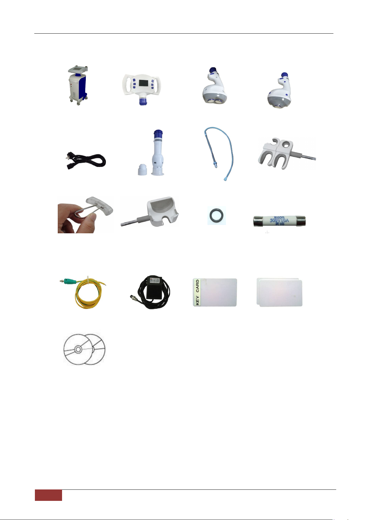
1.1Parts........................................................................................................................1
1.2Packing List.............................................................................................................2
Chapter 2 Safety..................................................................................................................3
2.1Optic Safety.............................................................................................................3
2.2Operation Safety.....................................................................................................3
2.3Safety Signs............................................................................................................4
2.4 Environmental Request..........................................................................................4
Chapter 3 Technical Specifications………………………………………………………….....5
Chapter 4 Installation...........................................................................................................6
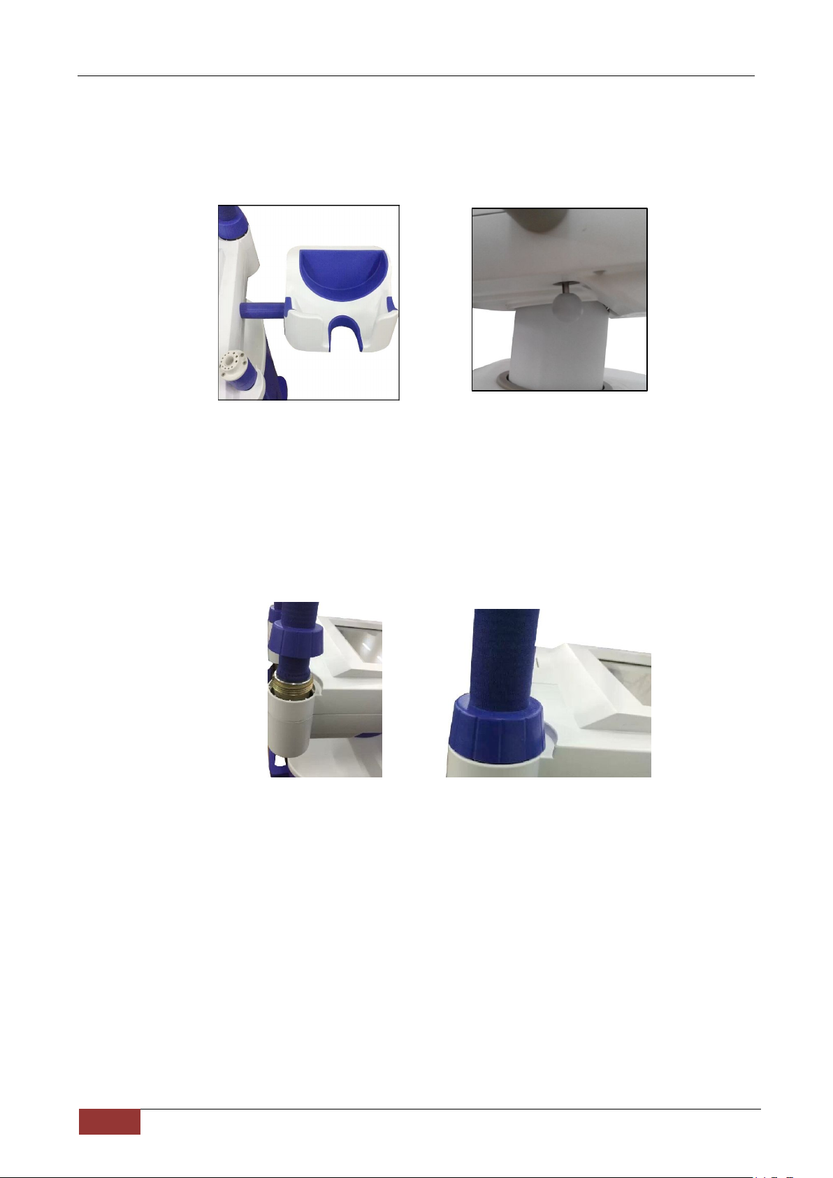
4.1Handpiece Installation and Disassemble................................................................6
4.2Fast Connector Installation and Disassemble ........................................................6
4.3 Connect the Handle with Fast Connector ...........................................................7
4.4 Change the Tip of Handpiece 4..............................................................................7
4.5 Earth Ground Wire Installation...............................................................................7
Chapter 5 Operation ............................................................................................................8
5.1 Start Equipment......................................................................................................8
5.2 Handpiece 1............................................................................................................8
5.3 Handpiece 2 and Handpiece 3.............................................................................10
5.4 Handpiece 4..........................................................................................................12
5.5 Ultrasonic Frequency............................................................................................13
5.6 IC Card..................................................................................................................13
5.6.1 Issue User Card.................................................................................................14
5.6.2 Issue Unlock Card.............................................................................................14
5.6.3 IC Card Applications..........................................................................................15
5.7 Footswitch.............................................................................................................15
5.8 Turn off Equipment...............................................................................................15
Chapter 6 Maintenance......................................................................................................16
6.1 Daily Maintenance................................................................................................16
6.2 Change Filter Element of Equipment...................................................................17
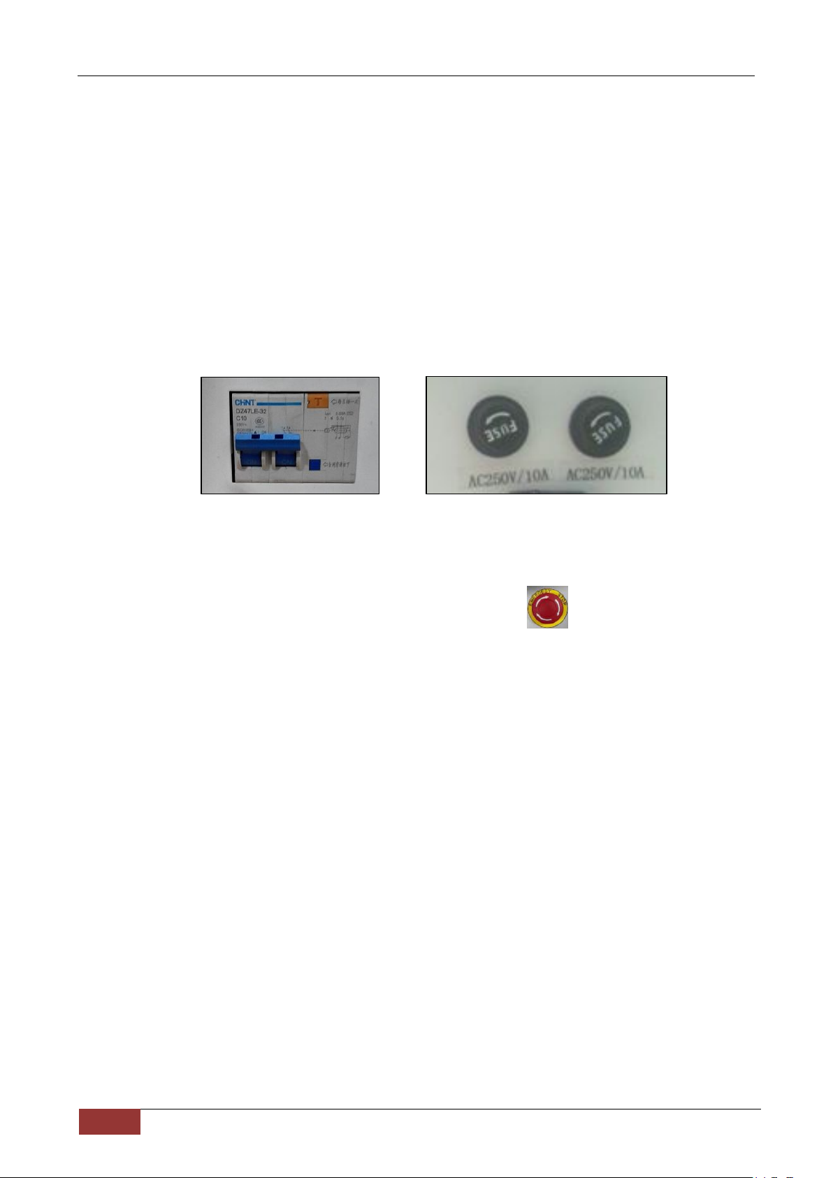
6.3 Emergency Switch................................................................................................17
6.4 Change the Fuse..................................................................................................17
Chapter 7 Troubleshooting ................................................................................................18
7.1 Guarantee.............................................................................................................18
7.2 Troubleshooting....................................................................................................18
Chapter 8 Clinical Guide....................................................................................................19
8.1Working Mechanism..............................................................................................19
8.2Applications...........................................................................................................19
8.3Contraindications...................................................................................................19
8.4Notes of Using Cavitation Handpiece...................................................................19
8.5Parameters............................................................................................................19
8.6 Treatment Manner................................................................................................20
8.6After Treatment......................................................................................................21
8.7 Questions and Answers........................................................................................21

1//22
All rights reserved
Chapter 1 Equipment Parts
1.1 Parts
Power supply
Earth ground
Footswitch
Electricity breaker
Handpiece 1
Power switch
Emergency switch
10.4 inch touch color screen
Handpiece 3
Handpiece 2
Handpiece 4
FuseFuse

2//22
All rights reserved
1.2 Packing List
The host×1 Handpiece 1×1 Handpiece 2×1 Handpiece 3×1
Power line×1 Handpiece 4×1 Quick plug×2 Handpiece stand-Left
Filter element
extractor×1 Handpiece stand-Right
O Shape ring×10 Fuse×2
Grounding wire×1 Footswitch×1 Key card×1 Blank card×2
User manual×1

3//22
All rights reserved
Chapter 2 Safety
The operators and maintenance person shall be familiar with the safety requirements and procedures
when they use the equipment.
2.1 Optic Safety
1)The local power supply shall be AC230V±10%,50Hz±1Hz/AC110V±10%,60Hz±1Hz;
2)5 minutes later after unplug the power plug, you can make maintenance. Never leave the machine
with cover open, or there will be danger to the personnel or the equipment;
3)There is electricity breaker on the back of the machine (Picture 2.1-1)to prevent persons
from getting electric shock;
Picture 2.1-1 Picture 2.1-2
4)There are two fuses on the back the machine(Picture 2.1-2). If there is over electricity, the fuse
tube will break electricity to protect the machine;
5)The operator shall be familiar with the machine’s operation and know how to turn off equipment in
time. If the machine is in danger, press the emergency switch to cut off power supply;
6)There is dangerous high-voltage in the equipment. So no one is allowed to
disassemble any parts of the machine except for the technical personnel
appointed by our company;
7)After starting, the system will make self-check for connected handpiece, including handpiece
distinguish and optic safety;
8)Good grounding is very important to operation safety. This equipment has good grounding by
yellow and green wires in power line.
2.2 Operation Safety
1)To fix machine by step on the two front wheels like Picture 2.2-2 shows;
Unlock the machine for moving it like Picture 2.2-3 shows;
2) Lifting machine requires two people’s cooperation.
They are located around the machine, one hand grip the handle of upside, another hand pick the
metal base at the bottom of the machine. When they are ready, raise the machine
safely at the same time.

4//22
All rights reserved
2.3 Safety Signs
1) means grounding
2) “AC220V”or “AC110V” means rated input voltage;
3) “AC250V 10A” is the fuse model and rating;
Picture 2.2-2 Picture 2.2-3
2.4 Environmental Request
1) Air quality:
System shall work in the environment which has no corrosive substances, like acid, dust and so on;
2) Temperature and humidity:
Work temperature:10-30℃Storage temperature:-10℃-50℃
Work relative temperature:20-60% Storage relative temperature:20-60%
3) Atmospheric pressure:860hPa ~ 1060hPa

5//22
All rights reserved
Chapter 3 Technical Specifications
Items Specifications
Screen 1. The host screen: 10.4 inch TFT color touch screen
2. Handpiece 1 screen: 2.5 inch
3. Handpiece 2 screen: 1.0 inch
4. Handpiece 3 screen: 1.0 inch
Safety test Real time online for safety test
Vacuum pressure 1) Absolute value: 15kPa -90kPa ;
2) Relative value: 85kPa -10kPa
Ultrasound frequency: 1MHz Ultrasound power: 60W (max)
Ultrasound frequency: 40kHz Ultrasound power: 60W (max)
Feature Wireless IC card management system
Handpiece 4 (fast connected and identify automatically)
Electricity shock protection I Class BF Type
Input power supply AC230V±10%,50Hz±1Hz/AC110V±10%,60Hz±1Hz
Input power 600VA
Net weight 55kg
Gross weight Paper packing: 65kg
Physical dimension Length 95cm× Width 50cm× Height 170cm
Package dimension Length 74cm×Width 78cm×Height 145cm

6//22
All rights reserved
Chapter 4 Installation
4.1 Handpiece Installation and Disassemble
1)Insert handpiece stand into A (Picture 4.1-1);
2)You will hear the sound, which means it is fixed well on the equipment;
3)Disassemble: Pull the handle(Picture 4.1-2), at the same time, take out the handpiece
stand;
4)The stand installation and disassemble of the two sides are the same.
4.2 Fast Connector Installation and Disassemble
1) Insert the fast connector into the hole (Picture 4.2-1);
2) Fix the nut (Picture 4.2-2);
Picture 4.1-1 Picture 4.1-2
Picture 4.2-1
Picture 4.2-2

7//22
All rights reserved
4.3 Connect the Handle with Fast Connector
1) Connect the handle with fast connector like Picture 4.3-1 shows;
2) Fix the nut(Picture 4.3-2)
4.4 Change the Tip of Handpiece 4
Picture 4.4-1 Picture 4.4-2
1) Handpiece 4 has 2 tips, one is bigger and the other is smaller. Insert the tip into the handle(Picture
4.4-1);
2) Slightly turn the tip(Picture 4.4-2)
4.5 Earth Ground Wire Installation
it could not be turned on, unless it is pressed.
It is earth ground wire. It is optional. If equipment conducts electricity, Picture 4.5-1
you can insert it into the equipment(Picture 4.5-1),connect the other
side of the earth ground wire to metal connecting the earth.
Picture 4.3-1
Fast connector
Handle
Picture 4.3-2
A
A
Nut

8//22
All rights reserved
Chapter 5 Operation
5.1 Start Equipment
1)Connect power supply, turn on electricity breaker, press power switch;
2)The initialization lasts for 5s(Picture 5.1-1);
Picture 5.1-1
If the handpiece lights, it means handpiece is well connected.
5.2 Handpiece 1
In Picture 5.2-1:
A:Standby;B:Ready;
C:Work time;D:Cavitation energy output;
E:Vacuum level;F:Absolute vacuum;
G:Pulse time;
a) Press “▲” “▼” key to select item to be adjusted;
b) Press “+” “-” key to adjust it;
c) Press “○” key to get ready for treatment;
d) You can adjust the items on the host screen;
e) When handpiece is in ready condition, you could not adjust the items.
Picture 5.2-1
C
D
B
A
E
G
F

9//22
All rights reserved
Picture 5.2-2
In Picture 5.2-2:
1) A area:If handpiece 1 is connected, touch it;
2) B area: shows working mechanism of handpiece 1;
3) C area: shows the defaulted parameters of handpiece 1:
i. To adjust cavitation power:
Touch and it turns to ; Press “ ” or “ ” to adjust energy.
The energy scope is 0-60W.
You can adjust it on the handpiece too.
ii. To adjust vacuum energy level:
Touch and it turns to ; Press “ ” or “ ” to adjust it.
You can adjust it on the handpiece too.
iii. To adjust pulse delay:
Touch and it turns to ; Press “ ” or “ ” to adjust it.
You can adjust it on the handpiece too.
iv. shows temperature of handpiece 1. When the equipment is ready, the indicator light of
handpiece 1 will shine.
Temperature < 50℃, the light shows yellow;
Temperature >50℃, the light shows red;
Temperature >60℃, the handpiece stops working;
4) E area
Press to change to situation

10//22
All rights reserved
5) F area shows its available treatment parts. Touch the picture you want and the treatment manner will
be showed at B area;
6) G area adopts countdown. Press or to adjust time;
7) D area shows timing function of IC card.
Issue a user card referring to 5.5.1;
Insert user card into the card slot and then the timing function is started;
The D area will show the user card time (0-99900 minutes);
If user card function is started, user card has to be inserted when you use this equipment;
To stop timing function of IC card:
Issue a unlock card referring to 5.5.2;
Make unlock card touch response area of the equipment;
5.3 Handpiece 2 and Handpiece 3
Handpiece 2 Handpiece 3 Picture 5.3-1
The function and working mechanism of the two handpiece are the same.
Handpiece 2 is bipolar cavitation and handpiece 3 is monopolar cavitation.
Handpiece 2 is suitable for bigger part and handpiece 3 is suitable for smaller part.
In Picture 5.3-1:
a) Press “+”, “-” key to adjust energy level(B, C);D shows the energy level;
b) Press “○” key to get ready for treatment(A);
c) You can also adjust cavitation energy level on the host screen;
d) Parameters could not be adjusted during ready;
Standby/Read
“+”, “
-
” key

11//22
All rights reserved
Picture 5.3-2 Picture 5.3-3
In Picture 5.3-2:
System will check online for handpiece connection. Touch the handpiece you want inA area;
F area: Touch treatment item in F area, for example, will change to . At the same time, B
area will show relative treatment manner (Picture 5.3-3).
C area:
shows temperature of handpiece 2 or handpiece 3.
When the equipment is ready, the indicator light of handpiece 1 will shine.
Temperature < 50℃, the light shows yellow;
Temperature >50℃, the light shows red;
Temperature >60℃, the handpiece stops working;
shows cavitation energy level.
Monopolar cavitaiton is 10-50W; bipolar cavitation is 10-60W.
You can adjust cavitation energy level by handpiece key too.
E area: Press to change to situation
F area: shows its available treatment parts. Touch the picture you want and the treatment manner will be
showed at B area;
G area: adopts countdown. Press or to adjust time;
D area: shows timing function of IC card.
Issue a user card referring to 5.6.1;
Insert user card into the card slot and then the timing function is started;
The D area will show the user card time (0-99900 minutes);
If user card function is started, user card has to be inserted when you use this equipment;
To stop timing function of IC card:
Issue a unlock card referring to 5.6.2;
Make unlock card touch response area of the equipment;
A
F
C
B E
G
I
D

12//22
All rights reserved
5.4 Handpiece 4
Picture 5.4-1
In Picture 5.4-1:
A: “-” key B: “o” key C: “+” key
Press “+”“-” key to adjust vacuum(A ,C);
Then press “o”(B)to be ready for treatment;
You can adjust it on the host screen;
Parameters could not be adjusted during ready;
Picture 5.4-2 Picture 5.4-3
In Picture 5.4-2:
System will check online for handpiece connection.
I area: touch the handpiece you want.A is big tip; B is small tip;
E area: Press to change to situation
F area: shows its available treatment parts. Touch the picture you want and the treatment manner will be
showed at J area (Picture 5.4-3);
G area adopts countdown. Press or to adjust time;
D area shows timing function of IC card.
Issue a user card referring to 5.6.1;
Insert user card into the card slot and then the timing function is started;
The D area will show the user card time (0-99900 minutes);
If user card function is started, user card has to be inserted when you use this equipment;
To stop timing function of IC card:
Issue a unlock card referring to 5.6.2;
A
B
F
C
J
D
E
G
I
A
B
C
I
D

13//22
All rights reserved
Make unlock card touch response area of the equipment;
C area: shows duration and vacuum of handpiece 4.
5.5 Ultrasonic Frequency
Picture 5.5-1 Picture 5.5-2
After you change the power supply, ultrasonic handpiece, or find energy increase or decrease, you
shall adjust the frequency.
1)Press key for 3s(Picture 5.5-1); then system shows Picture 5.5-2;
2)Connect the handpiece needing check with the left connector, not the right connector (Picture
5.5-3); then relative picture turns yellow(Picture 5.5-2);
3)Bipolar cavitation of handpiece 1 is adjusted together;
4)Bipolar cavitation of handpiece 2 is adjusted separately; choose the left one or right one by
touching picture ;
Picture 5.5-3
5)Leave some water on the cavitation part, press “O”key, find the best frequency of water
shaking by “ ” key (Picture 5.5-3):the two parts’water shaking of handpiece 1 shall
be consistent;
6) After adjustment, press “O”key, press key; means success and means
failure and press , adjust it again;
7) Press to go back to main interface;
5.6 IC Card
The issued time is saved in the IC card, while, the equipment doesn’t save it.
So equipment has no function of loss report. But the equipment could manage countless persons.

14//22
All rights reserved
5.6.1 Issue User Card
Picture 5.6-1 Picture 5.6-2
1) After initialization, insert the key card (Picture 5.6-1)and screen shows Picture 5.6-2;
2) In Picture 5.6-2:
Press “+” or “-” key to issue time, 10 minutes for each press, 100 minutes for continual press;
The scope is 0-99900 minutes.
Insert a blank card into the card slot or make the blank card touch the card response area; the
system will issue user card automatically;
The screen will show “Issue OK!” or “Issue Error!”;
You can issue many user cards at a time;
Press to exit issuing interface;
5.6.2 Issue Unlock Card
Picture 5.6-3
1) After initialization, insert the key card (Picture 5.6-1)and screen shows Picture 5.6-2;
2) Touch like Picture 5.6-3 shows;
3) Insert a blank card into the card slot or make blank card touch the response area; the system will
issue unlock card automatically;
The system will notice “Issue OK!” or “Issue Error!”;

15//22
All rights reserved
You can issue many unlock cards at a time;
Press to exit issuing interface;
5.6.3 IC Card Applications
1. For agency
1) The agency can rent equipments for marketing and charge according to using time;
For example, the agency charges for 14400 minutes=30 days×8 hours/day×60 minutes/hour once:
ØIssue user card referring to 5.6.1 and the issued time is 14400 minutes;
ØInsert user card into the card slot and then the timing function is started;
ØGive the user card and equipment to customer;
The agency keeps the key card;
ØWhen the customer uses the equipment, he has to insert the user card into the card slot;
ØWhen the time is used out, the IC card fails and equipment is locked;
The customer has to pay for agency again to get a user card with 14400 minutes;
Then the customer can restart the equipment again;
ØIf the customer wants to buy the equipment, the agency gives the key card to him after charging;
2. For beauty salon
The beauty salon wants to charge according to treatment times.
For example, one customer needs 10 times of treatment, each treatment needs 30 minutes:
ØIssue user card referring to 5.6.1 and the issued time is 300 minutes (10 times x 30 minutes);
ØThe beauty salon charges for the issued user card and give the user card to the customer;
ØWhen the customer asks for treatment, insert the user card into the card slot;
Then set the time for this treatment;
When the set time is used out, the system will stop working automatically;
ØAfter treatment, the customer takes away his user card;
5.7 Footswitch
The footswitch can be used as the “o” key of handpiece;
The reasonable using of footswitch could bring convenience to operator;
5.8 Turn off Equipment
1) Put the handpiece on the stand;
2) System is standby;
3) Turn off power switch;
4) Turn off electricity breaker;
5) Take down the power line

16//22
All rights reserved
Chapter 6 Maintenance
Turn off the equipment and 5 minutes later you can maintenance this equipment.
Never leave the equipment with cover open and no personal care, or there will be danger to personnel or
system.
The maintenance of inner parts of the equipment shall be carried out by professional technical persons.
6.1 Daily Maintenance
1. Maintenance of handpiece 1, handpiece 2 and handpiece 3
Wipe the tip directly.
2. Clean the filter element of handpiece 1
After each treatment, take out the filter element and clean it;
In Picture 6.1-1, A is filter element extractor, B is filter element.
Procedure:
1) Insert filter element extractor into the filter element as Picture 6.1-2 shows;
Then take out the filter element;
2) Open the cover of the filter element with the extractor (Picture 6.1-3);
3) Clean the case and cover with water (Picture 6.1-4);
4) After cleaning, assemble the case and cover.
5) Make the cotton dip 70% alcohol solution and use it to wipe the filter element slot in handpece 1;
6)Put the filter element into the slot.
Picture 6.1-1 Picture 6.1-2
Picture 6.1-3 Picture 6.1-4
3. Clean handpiece 4
1) Slightly turn the tip and take it down;
Then tip containsAand B (Picture 6.1-5);
2) Clean A and B with water;
3) Wipe A and B with soft paper;
A
B

17//22
All rights reserved
4) Dry the place with warm wind where you could not touch;
Picture 6.1-5
6.2 Change Filter Element of Equipment
1) When the equipment works for one or two months, you have to change for new filter elements;
2) Unscrew A and B on the back of the equipment(Picture 6.2-1)and take out the filter elements;
3) Put a new filter element on A/B;
Note: The holes (C and D) shall well abutting joint;
4) Screw A and B
Picture 6.2-1
6.3 Emergency Switch
Turn on the equipment, when you press the emergency switch, the system will turn off at once;
Turn the emergency switch and start the equipment;
6.4 Change the Fuse
1) Turn off equipment, turn off electricity breaker, unplug the power wire from the socket;
2) Unscrew the fuse house on the back panel;
3) Take out the two fuses from fuse house and change for new ones of the same specifications;
4) Screw the fuse house ;
5) Connect power wire and turn on electricity breaker;
6) Turn on equipment.
Tip B
A
B
A
A/B
Filter element
C
D

18//22
All rights reserved
Chapter 7 Troubleshooting
7.1 Guarantee
The misusing or modifying may make the guarantee invalid.
7.2 Troubleshooting
Trouble Reason Measures
Start equipment failure
Trouble with power switch Contact with us
Didn’t insert power wire well Well insert the power wire
Fuse is broken Change the fuse
Trouble with controlling board Contact with us
Handpiece key has no response
Trouble with controlling board Restart equipment, if no response
still, contact with us
Touch screen key has no
response Trouble with touch screen Contact with us
Touch screen has no display Trouble with touch screen Contact with us
No vacuum or less vacuum Trouble with vacuum pump Contact with us
Trouble with AC contactor Contact with us
No cavitation Energy level is 0 Increase it
Trouble with controlling board Contact with us
If any trouble happens, please contact with us with following form: Thank you!
Your name: Country:
Seller: Model:
Trouble date: Control board number:
Special order: Yes or No
Did this trouble happen before? Yes or No? What was the solution?
What’s the trouble frequency? Occasionally? Sometimes? Always? All the time?
When will it happen? After start? Standyby? Ready?
(Initialization)
Version number:
(Back panel)
Equipment number:
(Handle)
Handpiece number:
Table of contents