MBW MK8-121 User manual

MK8-121
WITH HYDRAULIC CONTROLS
This manual covers the following serial
numbers and higher for each model
listed:
MK8-121……………………….1790049
MBW, Inc.
250 Hartford Rd · PO Box 440
Slinger, WI 53086-0440
Phone: (262) 644-5234
Fax: (262) 644-5169
Website: www.mbw.com
MBW (UK) Ltd.
Units 2 & 3 Cochrane Street
Bolton BL3 6BN, England
Phone: 01204 387784
Fax: 01204 387797
L19342 / 02.21.B
© MBW, Inc. 2021
Printed in the USA

2
Fig.1
Fig. 2
Fig. 3
Fig.3
Fig. 4
Fig. 5
Fig. 6
Fig. 7
Fig. 8
Fig. 9
Fig. 10
Fig. 11
1
Fig. 12
1
2
7
8
12
10
14
11
15
4
6
1 3
5
2
13
17
18
16
9
1
4
3
2
2
1
2
3
4
1

3

4
Thank you for buying our product. We have taken
every possible care to ensure that it arrives in
perfect conditions. Nevertheless, in the unlikely
event that you find some damage when you
receive the machine, or if we can help you in any
way, please do not hesitate to contact our
Customer Service department.
This manual contains all the information
necessary for proper use of the machine. Please
carefully follow the instructions and keep it in a
suitable and accessible place.
The contents of this manual may be
modified without prior notice or other
obligations in order to incorporate
changes and improvements to the units
already shipped.
It should be specified that for reasons of
visibility and clarity some figures are
shown with the machine not in the
correct configuration for use.
No part of this manual may be reproduced or
translated without permission in writing from the
manufacturer.

Table of Contents
1. SYMBOLS................................................................................................................................................. 6
2. GENERAL PRECAUTIONS FOR USE..................................................................................................... 6
3. TECHNICAL CHARACTERISTICS .......................................................................................................... 7
3.1. Machine Description .......................................................................................................................................... ..7
3.2. Technical Data and Details................................................................................................................................ ..7
3.3. Main Parts of the Machine and Controls............................................................................................................ ..8
3.4. Seat Adjustment................................................................................................................................................. ..8
3.5. Blade Inclination Adjustment.............................................................................................................................. ..8
3.6. Joysticks ............................................................................................................................................................ ..8
3.7. Ambient Conditions............................................................................................................................................ ..8
3.8. Not Permitted Uses............................................................................................................................................ ..8
4. DELIVERY AND INSTALLATION............................................................................................................. 8
4.1. Delivery.............................................................................................................................................................. ..8
4.2. Component Assembly........................................................................................................................................ ..9
4.3. Water Supply..................................................................................................................................................... ..9
4.4. Fuel.................................................................................................................................................................... ..9
4.5. Engine Oil .......................................................................................................................................................... ..9
5. USE............................................................................................................................................................ 9
5.1. Preliminary Checks............................................................................................................................................ ..9
5.2. Starting .............................................................................................................................................................. ..9
5.3. Driving the Float Machine.................................................................................................................................. 10
5.4. Use .................................................................................................................................................................... 10
5.5. Stopping............................................................................................................................................................. 10
5.6. Stopping in Emergency Conditions.................................................................................................................... 11
6. HANDLING AND TRANSPORT.............................................................................................................. 11
7. MAINTENANCE ...................................................................................................................................... 11
7.1. Engine Maintenance.......................................................................................................................................... 11
7.2. Machine Maintenance........................................................................................................................................ 11
7.3. Battery ............................................................................................................................................................... 12
7.4. Cleaning the machine........................................................................................................................................ 12
7.5. Replacing the Floats.......................................................................................................................................... 12
7.6. Replacing the Blades......................................................................................................................................... 12
7.7. Replacing the belts ............................................................................................................................................ 12
7.8. Gear Reduction Oil Level................................................................................................................................... 12
7.9. Storage Instructions........................................................................................................................................... 13
7.10. Hydraulic Pressure Regulation........................................................................................................................... 13
7.11. Parts List............................................................................................................................................................ 14
7.12. Troubleshooting................................................................................................................................................. 51
8. DISPOSAL............................................................................................................................................... 52
9. GUARANTEE.......................................................................................................................................... 52

6
1. SYMBOLS
Below follows a short legend with an indication of
the symbols used throughout the manual (those
considered most significant).
WARNING DANGER: draws the
attention to situations or problems
which may cause injury to persons or
risk of death.
IMPORTANT: draws the attention to
situations or problems connected with
machine efficiency but which do not
pose a risk to the safety of persons.
The following instructions are indicated on the
machine (Fig. 2):
No.
Description
1
Danger:
• Carefully read the instruction manual
• Do not let unauthorised persons come near the
working area
• Carry out maintenance work only when the machine is
off and after having pulled out the key and read the
instruction manual.
• Do not remove the protection and safety devices
• Rotating parts: risk of injuring the limbs.
• Hot surfaces: risk of burns
• Rotating tools: risk of injuring the limbs.
2
Protect hearing with earmuffs
3
CE plate
Observe the warnings on the plates.
Inobservance may cause death or injury
to the personnel. Ensure that the plates
are always present and legible. If
otherwise, apply or replace them.
2. GENERAL PRECAUTIONS FOR
USE
The operator is personally
responsible for the operating safety
of the machine.
Carefully read this manual before
starting, use, maintenance or other
operations on the machine.
The purpose of this manual is to
bring to the attention of the
operator, with illustrations and
texts, the fundamental instructions
and the criteria to follow for use and
maintenance of the machine.
In order to operate in safety:
Check that the machine has not
been damaged during transport,
and if so, immediately notify the
manufacturer or the area
representative.
Allow only authorised personnel
to use the machine.
Operators not working on the
machine must keep the safety
distance when the machine is
running.
Periodically clean the machine,
removing any foreign materials
which may compromise operation
or cause injury to the operator.
Before using the machine, ensure
that all the protection devices are
properly in place and in good
working order.
Should the protection devices be
faulty or damaged, replace them
immediately.
Carry out maintenance work only
after having read the instruction
manual and having pulled out the
ignition key or detached the spark
plug.
Any repairs may exclusively be
carried out by qualified personnel
using original spare parts.
Otherwise, the user may be
exposed to serious risk.
Do not wear clothes that may get
caught up in moving parts, such as
loose-fitting garments, scarves,
coats, etc. It is recommended to
wear approved garments for
accident-prevention purposes, for
example: hard hats, anti-slip
shoes, earmuffs, safety goggles,
heatproof gloves, safety mask.
Ask your employer about the
safety regulations in force and the
safety devices.

7
3. TECHNICAL CHARACTERISTICS
3.1. Machine Description
The double rotary float machine model MK8/10
120 has been designed and constructed to float
concrete and bituminous floors of warehouses,
car parks, cycle tracks, parking areas, pavements,
etc. For this purpose the machine is equipped with
two rotors, one turning clockwise and the other
counter-clockwise.
Both the engine and the operator’s seat are fixed
to a frame connected to both rotors.
The very low position of the seat has the following
advantages:
Superior planarity of the floor surface (as a
result of lowering of the machine barycentre)
Perfect vision
The seat can be adjusted to the most comfortable
driving position for the operator. All the steering
components, joysticks, joints, drive shaft and gear
reductions are protected by a tunnel to prevent
cement encrustations from accumulating over
time which could lead to more rapid wear of the
mechanical components.
3.2. Technical Data and Details
Description
Unit
Measure
Cod
3345/3318
Cod
3348/3319
Cod 3351
Cod
3352/3310
Cod
3354/3312
Cod
3353/3313
Dimensions
[mm]
2450x1205x1040
2450x1205x1040
2450x1205x1040
2450x1205x1040
2450x1205x1040
2450x1205x1040
Packaging
dimensions
[mm]
2530x1280x1100
2530x1280x1100
2530x1280x1100
2530x1280x1100
2530x1280x1100
2530x1280x1100
Operatine weight
[kg ]
375/385
390/400
390
372/382
380/390
395/405
Shipping weight
[kg ]
375/385
475/485
475
370/380
475/485
475/485
Motorization
-
Kohler
Kohler
Kohler
Honda
B&S Vanguard
B&S Vanguard
Power installed
[Hp]
25
40
32,5
24
31
35
Starting
-
Electric
Electric
Electric
Electric
Electric
Electric
Cooling
-
Air
Air
Air
Air
Air
Air
Fuel
-
Gasoline
Gasoline
Gasoline
Gasoline
Gasoline
Gasoline
Fuel tank capacity
lt
11
11
11
11
11
11
Max engine rotation
speed:
[rpm]
3600
3600
3600
3600
3600
3600
Min-Max blade
rotation speed
[rpm]
70-125
70-125
70-125
70-125
70-125
70-125
Rotor Diameter
[mm]
1200
1200
1200
1200
1200
1200
Number of blades
-
8/10
8/10
8
8/10
8/10
8/10
Max forward speed
[m/min]
90
90
90
90
90
90
Acoustic pressure
level
[dB]
(93.2)
93.2
93.2
93.2
93.2
93.2
Acoustic pressure
level at driver’s seat
[dB]
(97.10)
97.10
97.10
97.10
97.10
97.10
Acoustic power
level
[dB]
(109.4)
109.4
109.4
109.4
109.4
109.4
Quadratic mean
value of
acceleration
m/s2
0,8 - 1
0,8 - 1
0,8 - 1
0,8 - 1
0,8 - 1
0,8 - 1
(1) Measured with petrol-powered engine

8
An exact description of the Model and Serial
Number will make it easier for our Technical
Service to respond quickly and efficiently.
Therefore, always indicate the machine model
and serial number when you contact Technical
Service.
3.3. Main Parts of the Machine and Controls
See Fig. 1
N.
Description
1
Right rotor
2
Left rotor
3
Right float adjustment knob
4
Left float adjustment knob
5
Accelerator
6
Protection cage
7
Battery
8
Fuel tank
9
Water tank (Fig. 2)
10
Right control joystick
11
Left control joystick
12
Right headlight
13
Left headlight (Fig.2)
14
Seat
15
Engine
16
Oil tank (Fig.2)
17
Hydraulic pump (Fig.2)
18
Pressure gauge (Fig.2)
NB: For reasons of description the
machine may be represented without the
protection devices. The machine cannot
and must not be operated in these
conditions. At the time of installation, every
precaution must be taken to ensure that
the protection and safety devices are in
place and efficient.
3.4. Seat Adjustment
For horizontal adjustment, operate the lever (Fig.
3 No. 4) located under the seat (1). Find the
desired position and release the lever (4).
3.5. Blade Inclination Adjustment
The blade inclination can be adjusted with the
knobs (Fig. 4 No. 1 & 2).
Turn the knob (1) clockwise to increase the blade
inclination of the right rotor (Fig. 1 No. 3).
Turn the knob (2) clockwise to increase the blade
inclination of the left rotor (Fig. 1 No. 4).
To decrease the inclination, turn the knobs
counter-clockwise.
3.6. Joysticks
The machine has two joysticks, one on the left-
hand driver’s side (Fig. 5) which executes two
movements (forward and backward) and one on
the right-hand side (Fig. 6), which executes four
movements (forward, backward, right and left).
The machine movements are controlled by a
pressure regulating valve (Fig. 7) located in the
lower part of the machine.
3.7. Ambient Conditions
The machine should be used sheltered from
atmospheric agents.
The places where the machine is used should be
well ventilated and conform to the regulations in
force regarding hygiene and safety in the
workplace.
Do not come close to the
machine with naked flames or similar.
Do not use the machine in
places where there is a risk of
explosion or fire.
IMPORTANT: The exhausts contain
carbon monoxide, a hazardous mortal
gas. Do not start the engine in closed or
badly ventilated places.
3.8. Not Permitted Uses
It is prohibited to employ the machine for uses
different from those expressly indicated by the
manufacturer.
4. DELIVERY AND INSTALLATION
4.1. Delivery
All the material shipped, including the detached
parts, are checked before delivery.
Upon receipt check that the machine has
arrived intact in all of its parts. If
otherwise, immediately contact our
dealer.
The machine is delivered in a crate weighing
about 370 kg.
Unload it with a forklift truck of adequate capacity
and position it on a stable and horizontal surface.
Remove the top and side packaging and lift the
float machine with a crane using suitable metal
cables hooked onto the attachment at the center
of the machine.
The float machine is shipped fully assembled
except for the seat and the engine-side headlight;
moreover, the two steering levers are lowered and
the battery cable is detached.

9
The machine handling operations must
be carried out in observance of the
regulations in force regarding safety in
the workplace.
Dispose of the packaging in the
appropriate manner in accordance with
the regulations in force in the country of
use.
4.2. Component Assembly
Seat Assembly: Attach the seat (Fig. 3 No. 1) to
the support plate (2) using the 4 bolts. Fully
tighten the nuts and connect the terminal (3) to
the seat cable (4).
Headlight Assembly: Fit the headlight (Fig. 1 No.
5) in such a way that it is tight enough to resist
rotation and movement, fit the ground cable,
screw on and tighten the counternut, fit the power
cable into the plugs (Fig. 8).
Battery Cable Connection: Remove the cover
and connect the relevant cable to the positive pole
(Fig. 9 No. 2) of the battery (1), appropriately
tightening the terminal.
4.3. Water Supply
The hydraulic float machine MK8 120 has an
autonomous wetting system. The water is sprayed
in correspondence to the rotors from the nozzles
connected to the water tank.
When filling the tank, be careful not to confuse the
water tank (Fig. 2 No. 9) with the fuel tank (Fig. 1
No. 8).
4.4. Fuel
WARNING: Danger of explosion and
fire.
Fill the tank in an open place away from
heat sources. Do not smoke. Do not
refuel when the engine is running or very
hot.
IMPORTANT:
Consult the engine manual for the type
of fuel to use.
1. Clean the area around the fuel filler cap.
2. Remove the cap.
3. Fill the tank up to 3-4 cm from the brim in
order to allow the fuel to expand.
4. Close the filler cap.
5. Always thoroughly clean the area around
the cap removing any small spills.
4.5. Engine Oil
Refer to the engine manual attached.
Dispose of used oil in the appropriate
manner in accordance with the
regulations in force in the country of use.
5. USE
5.1. Preliminary Checks
Before proceeding with starting and use of the
float machine, do the following:
1. Check the oil level in the engine and, if
necessary, top off (see Par. 4.5).
2. Check the fuel level in the tank and, if
necessary, refuel (see Par. 4.4).
3. Check that all the protection devices are
present and working.
4. Adjust the seat position horizontally to
obtain the best possible working position
(see Par. 3.4).
5. Check that the blade is inclined by at least
1 cm in order to have better control over
the float machine when starting (for
adjustment see Par. 3.5).
6. Ensure that the float machine is
positioned on a flat surface with a
capacity of more than 300 kg/m2and that
there is sufficient space around the float
machine (at least 2 m).
5.2. Starting
In order to prevent slippage and losing
control of the float machine when
starting and during the working phases
the operator must be seated in the
driver’s seat on the float machine and
always hold the accelerator pedal in the
idle position.
To start the float machine operate as follows:
1. Sit in the driver’s seat after appropriately
adjusting its position and with the feet
resting on the footboard.
2. Clos the choke (for petrol-powered
engines only).
3. Position the accelerator hand-lever or
accelerator pedal (Fig.1 No.5) in the idle
position.
4. Turn the ignition key.
5. After starting, open the choke (for petrol-
powered engines only).

10
The engine is started at reduced rpm, the clutch
has not yet engaged and the rotors do not yet
rotate (the clutch engages at 1500 rpm). In order
to prevent slippage which might lead to rapid wear
of the clutch, firmly push the accelerator to reach
a value of 2500 rpm.
For more specific information on starting
consult the engine instruction manual.
5.3. Driving the Float Machine
Use the machine at reduced speed until
you have fully mastered it and all the
possible movements.
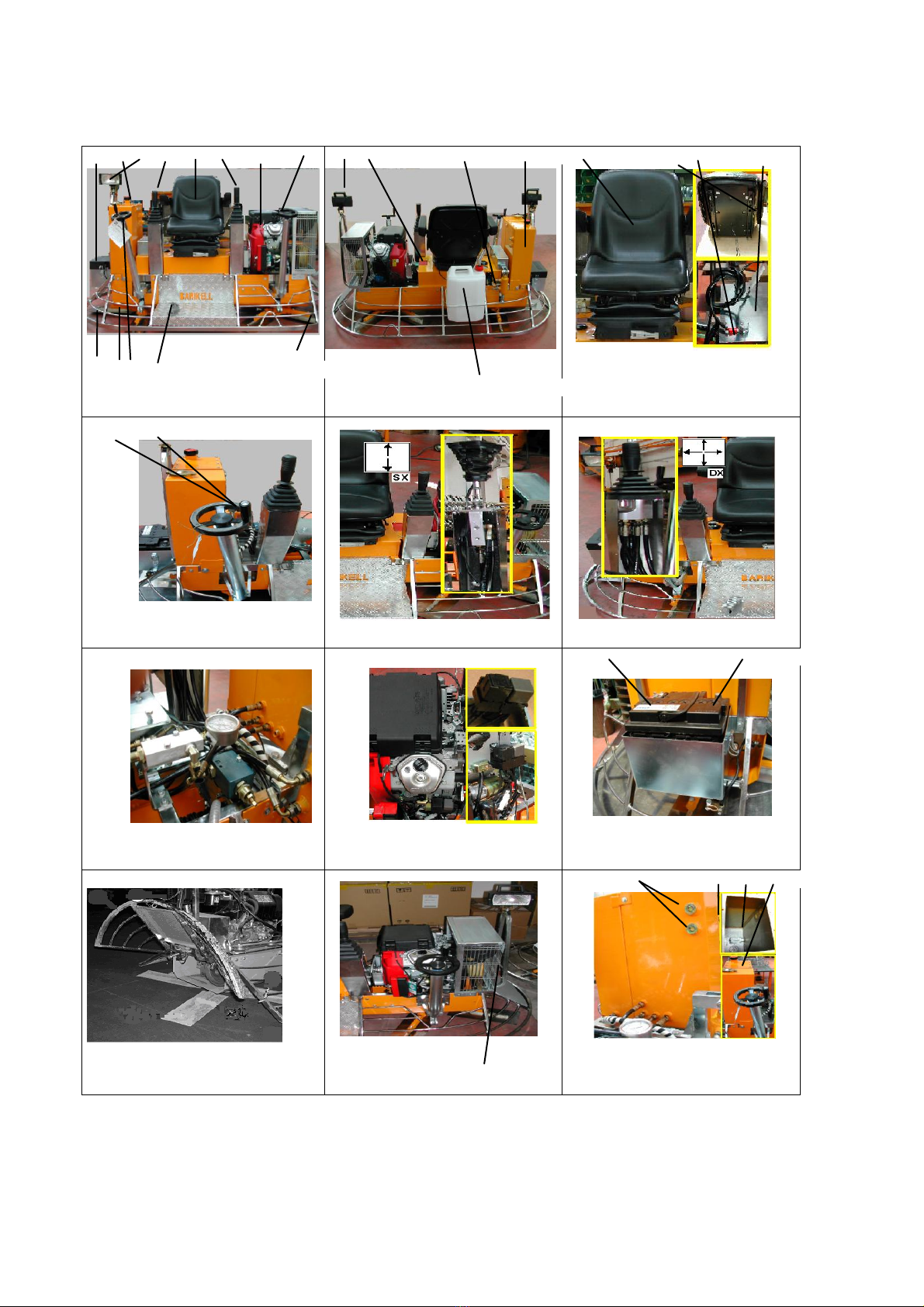
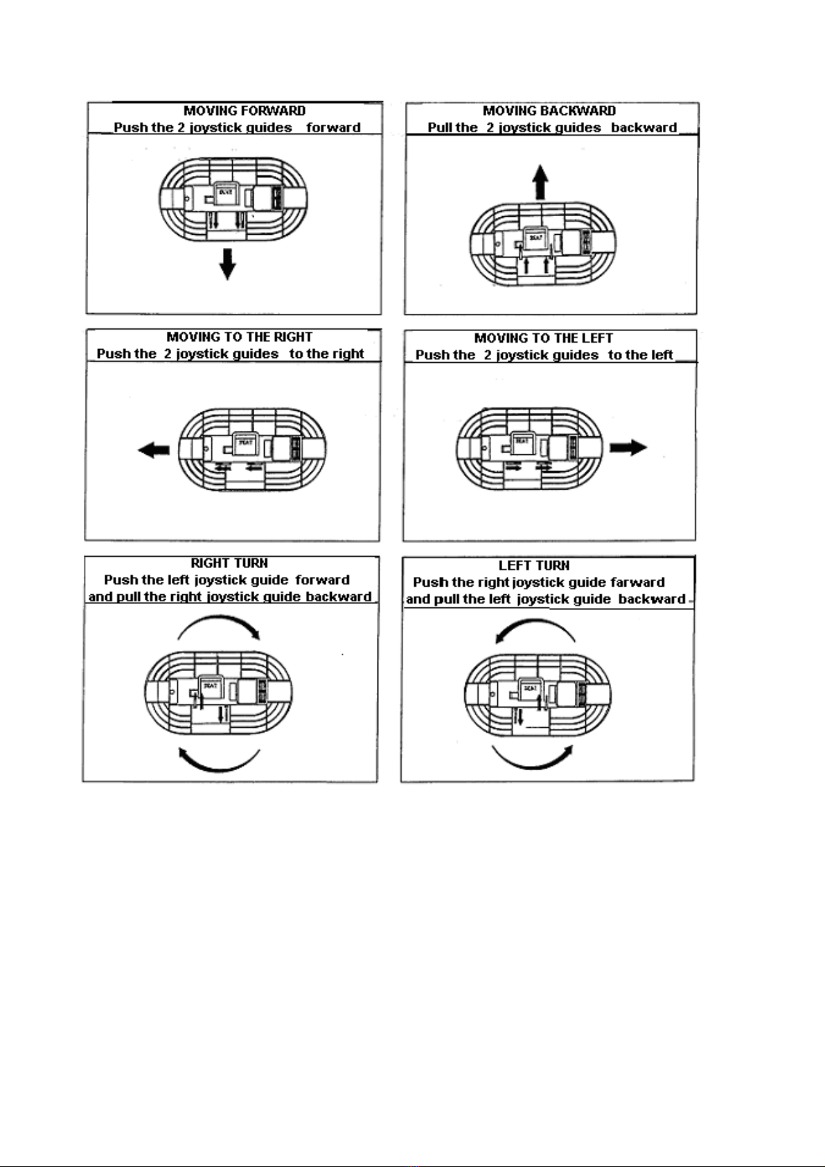
To drive the machine in the desired direction,
there are two control joysticks (Fig. 1 No. 10 &
11). Move the joysticks slowly and smoothly. To
stop the float machine movement, return the
joysticks to the rest position. The joystick control
positions and the relevant movements are
described on page 3 of this manual.
5.4. Use
For reasons of stability it is
recommended to use the machine on a
flat, stable and horizontal surface. Do
not use the machine on slopes of more
than 4%-5% gradient.
During the working phases, be
particularly careful not to lose control of
the float machine (for example, due to
too much water on the surface to be
worked).
Check that there are no obstacles or
obstructions on the working surface or
projecting parts which may hinder
rotation of the blades.
Preparing the Surface:
Use a mechanical vibrating float or manual float to
level the floor surface in order to obtain a well-
compacted concrete footing and thus prepare the
ideal surface for floating and finishing. The float
machine does not improve planarity of a badly
floated or levelled floor.
Floating Phase:
IMPORTANT: Before starting the
floating operation, check that the floats
have been mounted correctly on the
blades (Par. 7.5).
The floor is ready for the first pass when the
imprint of the shoe heel sinks into the concrete by
about 2-3 mm when walking on it.
The floating pass intervals depend on the ambient
factor, temperature and atmospheric conditions
(cold or hot season). On average about 250-300
m2of surface are floated in 10 minutes.
When the concrete is still fresh, take care not to
work continuously on the same spot since,
considering the weight of the float machine, you
might cause damage to the planarity of the floor
surface.
During the floating phase the floats must not
bounce on the surface. This might be caused by
dirt between the blades and the floats (if
necessary, clean them after you have finished
work following the instructions given in the
paragraph on cleaning).
Finishing Phase
When floating has been completed, detach the
floats from the blades and clean the cement that
has collected during the floating phase off the
blades, the spider and the protection rim. Turn the
blade-lifting knob clockwise (Fig. 4 No.1 & 2) until
the blades are inclined by about 1 cm for the first
pass. For the subsequent smoothing operations
continue increasing the blade inclination until
obtaining the desired finish.
Once again, the time between one pass and the
next is determined by the atmospheric conditions
(hot or cold season) and by the amount of water in
the concrete. If the concrete has hardened too
quickly in some areas, it can be moistened by
spraying a small amount of water using the button
(Fig. 1 No.11) located on the control bars in order
to obtain the degree of finish desired.
IMPORTANT: Switch off the engine
after each operation. Never leave the
float machine standing with the engine
running, especially during the floating
phase when the concrete is still fresh.
5.5. Stopping
For more specific information on
stopping, consult the engine instruction
manual.
To stop the float machine move the accelerator
(Fig. 1 No. 5) to idle and release the two joysticks
(10 & 11). Close the fuel cock and remove the
start key from the control panel.

11
5.6. Stopping in Emergency Conditions
The seat (Fig. 3 No. 1) is connected to a
microswitch which cuts the electric power to the
engine. In case of an emergency or loss of control
of the float machine, immediately release the
joysticks.
6. HANDLING AND TRANSPORT
Horizontal Movements
The float machine can comfortably be moved on
horizontal surfaces on construction sites using the
special trolley.
1. Pull the key out of the control panel.
2. Holding the handle of the trolley raised,
position it on the float machine straddling
the engine in such a way that the two
hooks near the wheels slide underneath
the protection rim until slipping into the
catch found under the bar of the rim.
3. Lower the handle of the trolley towards
the ground until the pivoting wheel
touches the floor and, holding the trolley
firmly down with the feet or with one hand,
hook it to the protection rim of the float
machine.
4. Move the machine by pushing or pulling
the handle until arriving at the new place
of work.
5. To unhook the trolley, detach the hook
from the catch.
The moment the float machine is
unhooked from the trolley, it will jolt
upward due to the effect of the machine
weight. Therefore, firmly hold the trolley
handle during this operation.
Vertical Movements
Never leave the floats attached to the
float machine when lifting it more than
100 cm off the ground since it could
detach and cause damage to persons
and things.
Lift the float machine using the lifting attachments.
To lift the machine from one level to another, use
a hoisting crane or lift truck of suitable capacity
with respect to the weight indicated in the
technical characteristics.
To transport the machine on a truck, place the
blades in horizontal position using the control
knobs. Transporting the float machine with the
blades inclined may damage the blade lifting
system.
7. MAINTENANCE
1. All the maintenance, inspection
and cleaning operations of the
machine must be carried out only
when the machine is off and cold.
2. Pull out the start key.
3. Before proceeding with
maintenance, thoroughly clean the
float machine.
4. When the blades are worn they
may become sharp. Therefore,
during all the maintenance phases,
wear protective gloves and pay
particular attention to their position.
7.1. Engine Maintenance
See the engine use and maintenance manual.
7.2. Machine Maintenance
The hydraulic float machine model MK8 120 does
not require any particular maintenance.
Nonetheless it is good practice to do the following:
Daily Operations
1. When you have finished work, thoroughly
clean off the encrustations that have
accumulated on the float machine during the
working phases.
2. Clean the engine air filter, especially if
working in dusty conditions (follow the
instructions in the engine manual).
3. Check tightness of the screws and bolts
of the protection guards and the blades and
replace if defective.
IMPORTANT:
During the work, the gage’s temperature
oscillate from 90° to 120°; reliant on
external temperature.
The maxim temperature gap between
the 2 gearboxes is 20°.
If the temperature is too high, you must
check the oil. If the problem continues,
contact a service center.
Weekly Operations
1. Check wear and tensioning of the belts.
Grease the cardan shafts.
2. Check the battery charge and the level of
water in the cells, if necessary, top off
with distilled water only.
3. Clean any oxidation off the two battery
poles.

12
Operations after 100 hours of work
Check the oil level in the two gear reductions (see
Par. 7.8).
7.3. Battery
If the machine is not used for a long period of
time, disconnect the battery removing the cable
terminal from the positive pole (Fig. 9 No. 2). For
maintenance, consult the instruction and use
leaflet of the battery.
IMPORTANT:
Recharge the battery in a dry place.
Protect the contacts from dirt and water
stagnation. Do not spray with water.
Replacing the Battery (Fig. 9)
Handle the battery with particular care
since it contains acid.
1. Remove the protective cover unhooking
the two hooks.
2. Remove the connection terminals and
take care to first remove the negative one
(4) in order to prevent a short-circuit.
3. Extract the battery and replace it with one
with the same characteristics (45 Ah).
Dispose of the battery in the
appropriate manner in accordance
with the regulations in force in the
country of use.
7.4. Cleaning the machine
Clean the float machine at the end of each
working day to prevent that cement hardens and
forms encrustations on the machine. Wash the
dirty parts with a brush and water. Wet the parts
exposed to cement with “stripping” oil (never fuel
oil). Do not oil the rubber moving parts (belts,
etc.).
7.5. Replacing the Floats
Be careful when installing the machine. One rotor
turns clockwise and the other counter-clockwise,
therefore you need to check that the various
components have been properly arranged.
Before mounting the floats, check that the blades
are clean, i.e. that there are no traces or residues
of cement mixes. The blades must be placed in
horizontal position using the knobs (Fig.4 No.1 &
2).
To replace the floats proceed as follows:
Slightly lift the float machine off the ground (about
10 cm).
Mount the floats on the blades checking the
correct direction of rotation.
When the floats have been mounted, reposition
the float machine on the ground.
7.6. Replacing the Blades
Always check the state of wear of the blades and
if they are damaged or bent, replace them. For
proper functioning they need to be replaced
entirely.
To replace the blades, proceed as follows (Fig.
10):
Clean any working residue off the
float machine.
Open the guard by unscrewing the
two fixing bolts and hook the guard to the
chain.
Slightly lift the float machine off the
ground (about 10 cm).
Remove the fixing bolts of the blades
on each arm.
Mount the new blades fixing the bolts
with the respective split washers (check the
state of the bolts and replace them if
necessary).
When the blades have been
mounted, reposition the float machine on the
ground.
Reposition the guard and tighten the
bolts.
7.7. Replacing the belts
To replace the belts, operate as follows:
Dismantle the belt protection guard
(Fig. 11 No. 1).
Slightly lift the float machine off the
ground (about 10 cm) in order to be able to
freely turn the pulley and the clutch and thus
easily remove and replace the belts.
Loosen the belt tightener.
Remove the worn belts and replace
them with others of the same size.
Screw down the belt tightener until
the ideal tension is obtained.
Reposition the float machine on the
ground.
Reposition the guard (1).
7.8. Gear Reduction Oil Level
To check the oil level in the gear reductions,
follow the instructions below:
There are two caps on the side of the two gear
reductions. The top cap (Fig. 12 No. 1)
determines the oil level in the gearbox. Pay
particular attention when you notice oil in the
lower part of the float machine. Clean and check
where the leak comes from and take the
appropriate action.

13
Should the oil need to be topped off, use Mobil
Glygoyle 30 synthetic oil or equivalent.
Check the level on the gauges (2).
To replace the oil filter open the support (3),
unscrew the filter (4) and proceed with
replacement.
7.9. Storage Instructions
Never store the machine with fuel in the
tank in places where the fuel vapors
may come into contact with flames
and/or sparks.
If you can foresee that the machine will not be
used for more than one month, drain the fuel from
the tank in order to prevent the formation of
rubbery deposits. Also detach the battery.
If storing the machine in places where the
temperature might drop to below 0°C, drain out
the water tank.
7.10. Hydraulic Pressure Regulation
The operating pressure of the MK8-120 may vary
from 0 to 20 bar and is controlled by the pressure
regulator located behind the seat (Fig. 7).
The pressure is regulated by the user.

14
7.11. Parts List

15

16

17

18

19

20
This manual suits for next models
1
Table of contents
Other MBW Trowel manuals
Popular Trowel manuals by other brands

MULTIQUIP
MULTIQUIP JH55C Operation and parts manual

SPEEDCRETE
SPEEDCRETE POLE TROWEL manual

Dynapac
Dynapac BG39 Series Instructions and spare parts catalogue

MQ Multiquip
MQ Multiquip J36E2 Operation and parts manual

MULTIQUIP
MULTIQUIP Whiteman Series Operation and parts manual

MQ Multiquip
MQ Multiquip JS36/30H55DE Series Operation and parts manual