Table of Contents
Part 1
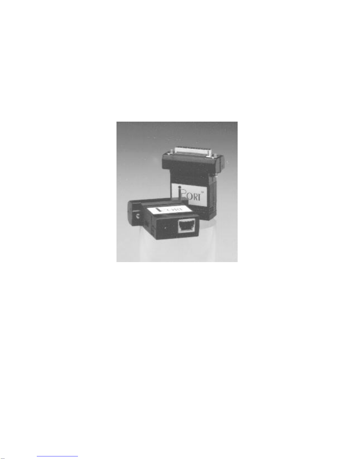
Windows to I2C Bus Host Adapter
Overview ........................................................1
iPortAdapter.................................................2
iPort Utility Pack Software ......................................2
iPort Software Development Kit for Windows (optional) ..............2
Packing Slip .....................................................2
System Requirements .............................................2
Interconnects ....................................................3
RS-232 Serial Port Connector ...................................3
DB-25 Serial Port Pinout .......................................3
DB-9 Serial Port Pinout ........................................3
+5VDCPowerJack ...........................................4
I2C Interface Connector ........................................4
Hardware Configuration ..........................................5
Pull-upResistors..............................................5
Connecting to a 3.3v System ........................................5
Connecting to an SMBus System ....................................5
Hardware Set-Up .................................................5
Part 2
iPort Utility Pack For Windows
Introduction to Utility Pack ........................................7
iPortMessageCenter .......................................... 7
iPortMessageManager ........................................ 8
System Requirements .............................................9
Software Installation ..............................................9
Introduction to Message Center ....................................10
I2CMessageOperations .......................................11