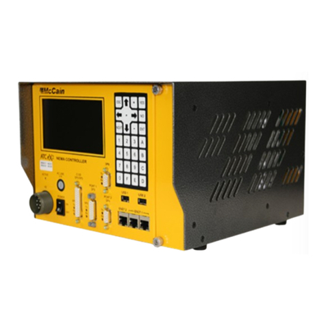
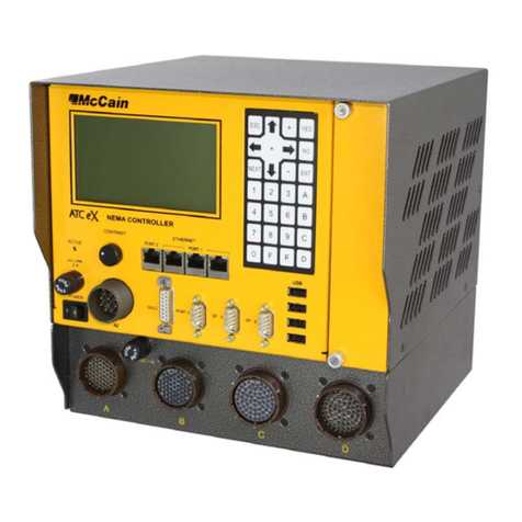
McCain ATC ex 2070N2 User manual

This page was intentionally left blank

Version
REVISIONS
Rev
By
Date
Comments
1.0
G. Rubio
2/21/2013
Initial Release
1.1
T. Reddan
6/10/2013
Manual photo and product naming conventions updated
1.2
R McAlpine
05/13/2015
Added M54111 part number, general formatting updates

DISCLAIMERS
User Responsibility
This document is subject to revision. Users of this document are responsible for verifying the current
version status before using this document and or discarding all older revisions.
McCain Inc. shall not be liable for errors contained herein or for incidental or consequential damages in
connection with furnishing, performance or use of this material. MCCAIN MAKES NO WARRANTY OF
ANY KIND WITH REGARD TO THIS MATERIAL, INCLUDING, BUT NOT LIMITED TO, THE IMPLIED
WARRANTIES OF MERCHANTABILITY AND FITNESS FOR A PARTICULAR PURPOSE.
This document contains proprietary and confidential information and is the sole property of McCain. No
part of this document may be photo copied, reproduced, or translated to another language without the
prior written consent of McCain.
This manual is copyright © 2015 by McCain Inc. All rights reserved.
McCain Inc. // 2365 Oak Ridge Way // Vista, CA 92081
PH 760-727-8100
Product Specifications: www.mccain-inc.com
Product Inquiries: 888-2-McCain (888-262-2246)

ATC eX 2070N2 Controller –User Manual i
Version 1.2
TABLE OF CONTENTS
1ATC EX 2070N2 CONTROLLER..........................................................................................1
1.1 Product Description.......................................................................................................................1
1.2 Benefits .........................................................................................................................................1
1.3 Configuration.................................................................................................................................2
1.4 Standard Features ........................................................................................................................4
1.5 Interfaces.......................................................................................................................................4
22070ATC CPU MODULE......................................................................................................5
2.1 General Description ......................................................................................................................5
2.2 Standard Features ........................................................................................................................6
2.3 Theory of Operation......................................................................................................................7
2.4 Communication Interface Descriptions .........................................................................................8
2.4.1 Host Board ..........................................................................................................................13
2.4.2 Engine Board.......................................................................................................................18
2.5 2070ATC Hostboard and Engine Board Block Diagrams..........................................................26
2.6 Connectors’ Pin Out: ...................................................................................................................29
2.7 Dimensions..................................................................................................................................32
2.8Adjustment ..................................................................................................................................32
2.9 Installing the 2070ATC CPU Module..........................................................................................32
32070-2N MODULE, FIELD I/O MODULE............................................................................33
3.1 General Description ....................................................................................................................33
3.2 Theory of Operation....................................................................................................................34
3.3 2070-2N Block Diagram..............................................................................................................35
3.4 Connectors’ Pin Out ....................................................................................................................36
3.5 2070-2N Field I/O dimensions.....................................................................................................37
3.6 Installing the 2070-2N Module ....................................................................................................37
42070-7A MODULE, ASYNC COMMUNICATION SERIAL BOARD...................................38
4.1 General Description ....................................................................................................................38
4.2 Theory of Operation....................................................................................................................39
4.3 2070-7A Block Diagram..............................................................................................................40
4.4 Connectors’ Pin Out: ...................................................................................................................41
4.5 The 2070-7A module dimensions: ..............................................................................................41
4.6 Adjustment ..................................................................................................................................42
4.7 Installing the 2070-7A Module.....................................................................................................43

ii
52070-3B MODULE, FRONT PANEL ASSEMBLY..............................................................44
5.1 General Description ....................................................................................................................44
5.2 Theory of Operation....................................................................................................................45
5.3 2070-3B Block Diagram..............................................................................................................47
5.4 Connectors’ Pin Out ....................................................................................................................48
5.5 The 2070-3B module dimensions: ..............................................................................................48
5.6 Adjustment ..................................................................................................................................49
5.7 Installing the 2070-3B Module.....................................................................................................49
62070-4N(A) POWER SUPPLY MODULE ...........................................................................50
6.1 General Description ....................................................................................................................50
6.2 Theory of Operation....................................................................................................................51
6.3 2070-4N(A) Block Diagram.........................................................................................................55
6.4 PS1 and PS2 Connectors’ Pin Out .............................................................................................56
6.5 2070-4N(A) Module Dimensions.................................................................................................57
6.6 Adjustment ..................................................................................................................................58
6.7 Installing the 2070-4N(A) Module................................................................................................58
7CHASSIS UNIT ...................................................................................................................59
7.1 General Description ....................................................................................................................59
7.2 Serial Motherboard......................................................................................................................61
7.2.1 Theory of Operation............................................................................................................61
7.3 2070 Serial Motherboard Block Diagram....................................................................................62
7.4 Connectors’ Pin Out: ................................................................................................................7-63
8GENERAL SPECIFICATIONS.........................................................................................8-69

ATC eX 2070N2 Controller –User Manual iii
Version 1.2
TABLE OF FIGURES
Figure 1: ATC eX 2070N2 Controller, Front and Rear Views.......................................................................2
Figure 2: ATC eX 2070N2 Controller System Configuration ........................................................................3
Figure 3: 2070ATC CPU Module..................................................................................................................5
Figure 4: 2070ATC CPU Module: Host Board and Engine Board................................................................7
Figure 5: 2070ATC CPU Module Dimensions............................................................................................32
Figure 6: 2070-2N Module ..........................................................................................................................33
Figure 7: 2070-2N Dimensions...................................................................................................................37
Figure 8: 2070-7A Module...........................................................................................................................38
Figure 9: 2070-7A Dimensions ...................................................................................................................41
Figure 10: Jumpers J1 and J2 ....................................................................................................................42
Figure 11: Jumpers J3 and J4 ....................................................................................................................42
Figure 12: 2070-3B Module.........................................................................................................................44
Figure 13: 2070-3B Dimensions .................................................................................................................48
Figure 14: Power Supply 2070-4N (A)........................................................................................................50
Figure 15: 2070-4N (A) Dimensions ...........................................................................................................57
Figure 16: 2070E Chassis unit....................................................................................................................59
Figure 17: Front and rear view 2070E Chassis...........................................................................................60
Figure 18: 2070 Serial motherboard...........................................................................................................61

iv
This page was intentionally left blank

ATC eX 2070N2 Controller –User Manual 1
Version 1.2
1 ATC EX 2070N2 CONTROLLER
1.1 Product Description
The ATC eX 2070N2 Controller is a ruggedized, multitasking field processor and communications system
that is easily configurable for a variety of traffic management applications in either a rack or shelf mount
configuration.
The ATC eX 2070N2 Controller has a general purpose nature, open architecture and modular design,
and its functionality depends on the software loaded into the controller and the modules included.
McCain’s ATC eX 2070N2 Controller, TS2 Type 1 compatible, is designed in full compliance with ATC
(Advanced Transportation Controller) 5.2b standards and Caltrans Transportation Electrical Equipment
Specifications (TEES) 2009 and Errata 1 January 21, 2010.
The McCain’s ATC eX 2070N2 Controller’s primary function is intersection control but can be used for a
multitude of applications based on the controller’s software.
The controller’s Linux operating system provides a robust, flexible and expandable platform that is
compatible with multi-vendor application control software.
1.2 Benefits
NEMA TS2 Type 1 compatible.
Compliant with current NEMA and ATC standards.
The controller’s multitasking operating system (OS) supports a variety of applications.
Open architecture ensures compatibility with off–the-shelf products.
Easily upgrades current intersection hardware.
Compatible with Omni eX®intersection control software (available separately) to provide superior
performance and advance control.

2
1.3 Configuration
This controller configuration is constructed as follows (See Figure 1):
2070 Chassis unit.
2070ATC CPU module.
2070-2N Field I/O module.
2070-3B Front Panel module.
2070-4N (A) Power Supply module.
2070-7A Asynchronous Serial Communications module.
Blank filler plates: There are four 2X and one 1X.
Front View
Rear View
Figure 1: ATC eX 2070N2 Controller, Front and Rear Views

ATC eX 2070N2 Controller –User Manual 3
Version 1.2
Figure 2: ATC eX 2070N2 Controller System Configuration

4
1.4 Standard Features
Operating system
Linux, Version 2.6.22
Modules (standard, included)
2070ATC CPU Module
2070-2N Field I/O module
2070-3B LCD/Front Panel Module
2070-4N(A) Power Supply
2070-7A Asynchronous Serial Communications module.
Microprocessors
MPC8360E Freescale PowerQUICC II Pro microprocessor
Backup real-time clock (RTC)
Maxim DS1390
Memory
16MB Flash memory
128MB DDR RAM (expandable)
2MB non-volatile SRAM
Applicable standards
Meets or exceeds Caltrans TEES 2009 standard
Meets or exceeds ATC (Advanced Transportation Controller) 5.2b standard
1.5 Interfaces
Communication interfaces
Up to five ports SDLC ports
Up to seven asynchronous ports
ENET 1: 100 Base-T Ethernet switch, 1 uplink and 4 additional ports
ENET 2: 100 Base-T Ethernet port dedicated for local communications (i.e. laptop or similar)
Two USB ports
Front panel interface
Display: 8 lines x 40 characters
Keyboards: 3 x 4 navigation and 4 x 4 data entry keypads
Cabinet interfaces
NEMA Port 1 C15S
NEMA TS2 Type A connector

ATC eX 2070N2 Controller –User Manual 5
Version 1.2
2 2070ATC CPU MODULE
2.1 General Description
The 2070ATC CPU Module is the brain of the controller; the design is fully compliant with the ATC 5.2b
standard.
The 2070ATC CPU features a wide variety of communication options, such as serial and Ethernet for
connectivity in any kind of environment. Quick data transfers, firmware upgrades, and log retrievals can
be done via USB.
The controller’s Linux operating system provides a robust, flexible, open-architecture platform that can
support third party applications.
The 2070ATC CPU is available with McCain’s user-friendly, NTCIP compliant Omni eX
intersection control software. This advanced software features a comprehensive ‘Help’ feature to
support technicians in the field. The software supports all NEMA and NTCIP standard controller
functions as well as a number of enhanced features for maximum flexibility.
It consists of a host board, an engine board and a faceplate (plus brackets, standoffs and hardware to fix
them to the host board).
Figure 3: 2070ATC CPU Module

6
2.2 Standard Features
Operating System: Linux, Version 2.6.22
Microprocessor: MPC8360E Freescale PowerQUICC II Pro communications processor
Backup real-time clock (RTC): Maxim DS1390
Memory:
16MB Flash memory
128MB DDR RAM (expandable)
2MB non-volatile SRAM
Communication interfaces:
Two SDLC ports
Four Serial (asynchronous)
ENET 1: 100 Base-T Ethernet switch, 1 uplink and 3 additional ports
ENET 2: 100 Base-T Ethernet port dedicated for local communications (i.e. laptop or similar)
Two USB ports

ATC eX 2070N2 Controller –User Manual 7
Version 1.2
2.3 Theory of Operation
The module contains all the circuitry for the CPU function: main processor, FLASH memory, SRAM, RTC,
a bidirectional buffer bank for the data, address lines and control lines coming from the processor, the
back-up capacitor, RESET circuit, isolation circuit for control signals coming from the power supply,
isolation circuit for SP8, C13S connector, Ethernet circuit, DATAKEY circuit, USB circuit, driver field circuit
(RS-485 transceivers), LINESYNC circuit, A2 and A3 connector sensor , and A5 connector.
The module is comprised of three main parts: A Host Board, an Engine Board and a Faceplate.
The faceplate is a 2X wide aluminum front plate with the necessary cutouts for the front connections; it
also has thumbscrews to be attached to the chassis.
The Host board and Engine board are shown in Error! Reference source not found.. These two major
assemblies are explained below in separated sections.
Figure 4: 2070ATC CPU Module: Host Board and Engine Board

8
2.4 Communication Interface Descriptions
Serial Port 1 (SP-1):
Usage: This is a general purpose port.
Location: available at the DIN-96 connector.
Operating modes: Asynchronous, Synchronous, HDLC, SDLC.
Async rates (bps): 1200, 2400, 4800, 9600, 19.2k, 38.4k / Optional: 57.6k, 115.2k.
Sync rates (bps): 19.2k, 38.4k, 57.6k, 76.8k, 153.6k.
Interface pins:
SP1_TXD: Transmit Data (O)
SP1_RXD: Receive Data (I)
SP1_RTS: Request To Send (O)
SP1_CTS: Clear To Send (I)
SP1_CD: Carrier Detect (I)
SP1_TXC_INT: Transmit Clock Internal (O)
SP1_TXC_EXT: Transmit Clock External (I)
SP1_RXC_EXT: Receive Clock External (I)

ATC eX 2070N2 Controller –User Manual 9
Version 1.2
Serial Port 2 (SP-2):
Usage: This is a general purpose port.
Location: available at the DIN-96 connector.
Operating modes: Asynchronous, Synchronous, HDLC, SDLC.
Async rates (bps): 1200, 2400, 4800, 9600, 19.2k, 38.4k / Optional: 57.6k, 115.2k.
Sync rates (bps): 19.2k, 38.4k, 57.6k, 76.8k, 153.6k.
Interface pins:
SP2_TXD: Transmit Data (O)
SP2_RXD: Receive Data (I)
SP2_RTS: Request To Send (O)
SP2_CTS: Clear To Send (I)
SP2_CD: Carrier Detect (I)
SP2_TXC_INT: Transmit Clock Internal (O)
SP2_TXC_EXT: Transmit Clock External (I)
SP2_RXC_EXT: Receive Clock External (I)
Serial Port 3 (SP-3):
Usage: To handle in-cabinet devices.
Location: available at the DIN-96 connector.
Operating modes: Asynchronous, Synchronous, HDLC, SDLC.
Async rates (bps): 1200, 2400, 4800, 9600, 19.2k, 38.4k / Optional: 57.6k, 115.2k.
Sync rates (bps): 153.6k, 115.2k.
Interface pins:
SP3_TXD: Transmit Data (O)
SP3_RXD: Receive Data (I)
SP3_RTS: Request To Send (O)
SP3_CTS: Clear To Send (I)
SP3_CD: Carrier Detect (I)
SP3_TXC_INT: Transmit Clock Internal (O)
SP3_TXC_EXT: Transmit Clock External (I)
SP3_RXC_EXT: Receive Clock External (I)

10
Serial Port 4 (SP-4):
Usage: External user interface and general purpose.
Location: available at the DIN-96 connector.
Operating modes: Asynchronous.
Async rates (bps): 1200, 2400, 4800, 9600, 19.2k, 38.4k / Optional: 57.6k, 115.2k
Interface pins:
SP4_TXD: Transmit Data (O)
SP4_RXD: Receive Data (I)
Serial Port 5 (SP-5):
Usage: To handle in-cabinet devices.
Location: available at the DIN-96 connector.
Operating modes: Synchronous, HDLC, SDLC.
Sync rates (bps): 153.6k, 614.4k.
Interface pins:
SP5_TXD: Transmit Data (O)
SP5_RXD: Receive Data (I)
SP5_TXC_INT: Transmit Clock Internal (O)
SP5_RXC_EXT: Receive Clock External (I)
Serial Port 6 (SP-6):
Usage: Front panel user interface.
Location: available at the DIN-96 connector.
Operating modes: Asynchronous.
Async rates (bps): 1200, 2400, 4800, 9600, 19.2k, 38.4k / Optional: 57.6k, 115.2k
Interface pins:
SP6_TXD: Transmit Data (O)
SP6_RXD: Receive Data (I)

ATC eX 2070N2 Controller –User Manual 11
Version 1.2
Serial Port 8 (SP-8):
Usage: General purpose.
Location: available at the C13S connector on Front plate.
Operating modes: Asynchronous, Synchronous, HDLC, SDLC.
Async rates (bps): 1200, 2400, 4800, 9600, 19.2k, 38.4k / Optional: 57.6k, 115.2k.
Sync rates (bps): 19.2k, 38.4k, 57.6k, 76.8k, 153.6k.
Interface pins:
SP8_TXD: Transmit Data (O)
SP8_RXD: Receive Data (I)
SP8_RTS: Request To Send (O)
SP8_CTS: Clear To Send (I)
SP8_CD: Carrier Detect (I)
SP8_TXC_INT: Transmit Clock Internal (O)
SPI (Serial Peripheral Interface):
Usage: Support Datakey and serial EEPROM interface.
Location: Datakey’s receptacle at Front plate and serial EEPROM on Host Board.
Operating modes: Synchronous.
Sync rates (bps): Application specific.
Interface pins:
SPI_MOSI: Master-Out-Slave-In (O)
SPI_MISO: Master-In-Slave-Out (I)
SPI_CLK: Clock (O)
SPI_SEL_1: Select 1 (O)
SPI_SEL_2: Select 2 (O)
SPI_SEL_3: Select 3 (O)
SPI_SEL_4: Select 4 (O)

12
Universal Serial Bus (USB) Port:
Usage: Facilitate the transfer of data files to/from the CPU by using USB memory devices as an
alternative to laptop computer.
Location: Two USB connectors at Front plate.
Requirements: Hardware and Software conforms to v2.0 USB devices to be used are formatted as
FAT16 file system providing a 2GB storage.
Interface pins:
USB_D+: Data Line Positive (I/O)
USB_D-: Data Line Negative (I/O)
USB_POWER_SWITCH Power Switch (O)
USB_OVERCURRENT Over-current (I)
Ethernet Interface (ENET):
Usage: Local and Network Communications.
Location: Two 10/100BASE-T Ethernet ports on Front plate, ENET1 (3) and ENET2 (1).
Operating modes: Synchronous, Manchester-encoded, and Differential.
Sync rates (bps): 10M, 100M.
Interface pins:
ENET1_TX_POS: Port 1 Transmit Data Positive (O)
ENET1_TX_NEG: Port 1 Transmit Data Negative (O)
ENET1_RX_POS: Port 1 Receive Data Positive (I)
ENET1_RX_NEG: Port 1 Receive Data Negative (I)
ENET2_TX_POS: Port 2 Transmit Data Positive (O)
ENET2_TX_NEG: Port 2 Transmit Data Negative (O)
ENET2_RX_POS: Port 2 Receive Data Positive (I)
ENET2_RX_NEG: Port 2 Receive Data Negative (I)
Table of contents
Other McCain Controllers manuals
Popular Controllers manuals by other brands
Festo
Festo CPX Instructions and Assembly
Infineon Technologies
Infineon Technologies TC1796 user manual

Burkert
Burkert 8696 operating instructions

Radio-tone
Radio-tone RT-CRC1 user guide

Samson
Samson series 43 Mounting and operating instructions
NXP Semiconductors
NXP Semiconductors MPC5644A Reference manual

