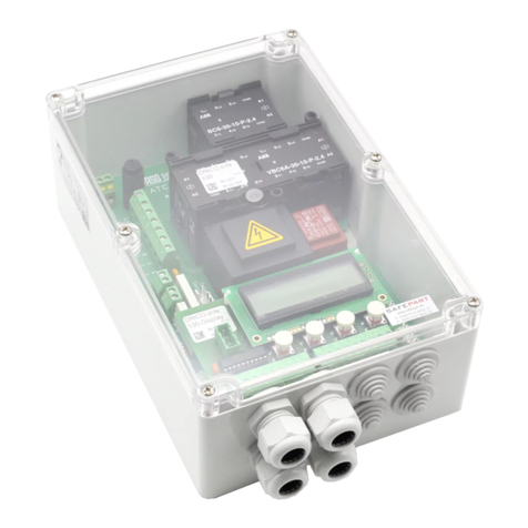
ASO SK 31 User manual

Betriebsanleitung
SK 31 Sicherheitsschaltgerät
Manual d’utilisation
SK 31 Dispositif de commutation de sécurité
Operating manual
SK 31 Safety Controller
Deutsch
Seite 3-9
English
Français
Page 10-16
Page 17-23
SK 31
Manuale d’istruzioni
Centralina di controllo SK 31
Italiano
Page 24-30

2

3
Allgemeine Sicherheitsbestimmungen und Schutzmaßnahmen
• Hersteller und Benutzer der Anlage / Maschine, an der die Schutzeinrichtung verwendet wird,
sind dafür verantwortlich, alle geltenden Sicherheitsvorschriften und -regeln in eigener Verant-
wortung abzustimmen und einzuhalten.
• Die Schutzeinrichtung garantiert in Verbindung mit der übergeordneten Steuerung eine funktio-
nale Sicherheit, nicht aber die Sicherheit der gesamten Anlage / Maschine. Vor dem Einsatz des
Gerätes ist deshalb eine Sicherheitsbetrachtung der gesamten Anlage / Maschine nach der
Maschinenrichtlinie 98/37 EG oder nach entsprechender Produktnorm notwendig.
• Die Bedienungsanleitung muss ständig am Einsatzort der Schutzeinrichtung verfügbar sein.
Sie ist von jeder Person, die mit der Bedienung, Wartung und Instandhaltung der Schutzein-
richtung beauftragt wird, gründlich zu lesen und anzuwenden.
• Die Installation und Inbetriebnahme der Schutzeinrichtung darf nur durch Fachpersonal
erfolgen, die mit dieser Betriebsanleitung und den geltenden Vorschriften über Arbeitssicherheit
und Unfallverhütung vertraut sind. Die Hinweise in dieser Anleitung sind unbedingt zu beachten
und einzuhalten.
Elektrische Arbeiten dürfen nur von Elektrofachkräften durchgeführt werden.
• Sicherheitsvorschriften der Elektrotechnik und der Berufsgenossenschaft sind zu beachten.
• Bei Arbeiten am Schaltgerät ist dieses spannungsfrei zu schalten und auf Spannungsfreiheit zu
prüfen.
• Wird der potentialfreie Kontakt des Relaisausgangs mit einer gefährlichen Spannung fremd-
gespeist, ist sicherzustellen, dass diese bei Arbeiten an dem Schaltgerät ebenfalls abgeschaltet
wird.
• Das Schaltgerät enthält keine vom Anwender zu wartende Bauteile. Durch eigenmächtige
Umbauten bzw. Reparaturen am Schaltgerät erlischt jegliche Gewährleistung und Haftung des
Herstellers.
• Das Schutzsystem ist in geeigneten Zeitabständen von Sachkundigen zu prüfen und in jederzeit
nachvollziehbarer Weise zu dokumentieren.
Sicherheitshinweise
• Nicht in unmittelbarer Nähe von starken Wärmequellen montieren.
• Bei kapazitiven und induktiven Verbrauchern ist für eine ausreichende Schutzbeschaltung zu
sorgen.
• Der Betrieb des Sicherheitsschaltgerätes im geöffneten Gehäusezustand ist nicht erlaubt.
Für die normenkonforme Auslegung des Sicherheitssystems nach
EN 954-1 Kategorie 2, muss vor jeder gefährlichen Bewegung der Anla-
ge / Maschine eine Testung des Sicherheitssystems erfolgen. Der Be-
trieb oder die Beschaltung des SK 31 Sicherheitsschaltgerät ohne
Testung erfüllt nicht diese Sicherheitsanforderungen.
Bei Nichtbeachtung oder vorsätzlichem Missbrauch entfällt die Haftung
des Herstellers.
Sicherheitsschaltgerät SK 31
Deutsch

4
Deutsch
Sicherheitsschaltgerät SK 31
Bestimmungsgemäße Verwendung
Das Schaltgerät SK 31 kann seine sicherheitsrelevante Aufgabe nur erfüllen, wenn es bestim-
mungsgemäß eingesetzt wird.
Die bestimmungsgemäße Verwendung des Schaltgerätes, ist der Einsatz als Schutzeinrichtung in
Verbindung mit Sicherheitskontaktmatten, Sicherheitsbumpern und Sicherheitskontaktleisten.
Ein anderer oder darüber hinausgehender Einsatz ist nicht bestimmungsgemäß. Für Schäden, die
aus nicht bestimmungsgemäßen Verwendungen entstehen, übernimmt der Hersteller keine Haf-
tung.
Der Einsatz bei Sonderanwendungen bedarf einer Freigabe vom Hersteller.
Allgemein
Das einkanalige Schaltgerät SK 31 findet seine Anwendung bei der Auswertung von
Sicherheitskontaktmatten, sowie bei der Absicherung von Quetsch- und Scherstellen
durch Sicherheitskontaktleisten und Sicherheitsbumpern.
Das Schaltgerät SK 31 ist für den Einsatz an Anlagen/Maschinen vorgesehen, die durch
eine übergeordnete Steuerung ein Testsignal vor jeder gefährlichen Bewegung zur Verfü-
gung stellen. In Verbindung mit dem Testsignal erfüllt das Schaltgerät die Sicherheits-
Kategorie 2 nach EN 954-1 „Sicherheitsbezogene Teile von Steuerungen“.
Die Ruhestromüberwachung des Signalgebers wird durch einen integrierten
Abschlusswiderstand im Signalgeber ermöglicht. Fließt der Soll-Ruhestrom, so ist das
Ausgangsrelais angesteuert und der Schaltkontakt geschlossen. Wird der Signalgeber
betätigt oder der Sicherheitskreis unterbrochen, öffnet der Relais-Schaltkontakt. Der
Überwachungszustand des Signalgebers und die angelegte Betriebsspannung werden
durch LED's angezeigt.
Power
12
OUT
Test
Signal 12-24 V PE L1 N
Actuate
Fault
13 14 X1 X2
IN AC/DC
S1
A
S1
Test Signal
S1 B
Signalanzeigen
LED Power grün
Versorgungsspannung
LED Actuate gelb
Signalgeber betätigt
LED Fault rot
Sicherheitskreis unterbrochen
Anschlussklemmen
PE, L1, N Versorgungsspannung 230V 50/60Hz
12-24 V AC/DC Versorgungsspannung 12-24 V AC/DC
X1,X2 Anschluß Signalgeber
Out 13-14 Sicherheits-Relais
Test Signal Testsignal-Eingang

5
Ausführungen und mechanische Befestigung
Version SK 31-31
Polycarbonat-Gehäuse mit Verschraubungen 1xM12 und 2xM16 für Aufputzmontage in rauer Umge-
bung.
Das Schaltgerät ist fachgerecht an einem geeigneten Montageort zu befestigen. Nach Entfernen des
Deckels kann das Gehäuse mit vier Schrauben befestigt werden.
Die Einbaulage des Schaltgerätes ist beliebig, sollte jedoch zum Schutz vor eindringender Feuchtig-
keit so montiert werden, dass die Kabeleinführungen nach unten zeigen.
Version SK 31-33
Schnappschieneversion für die Befestigung auf 35 mm DIN-Schiene im Schaltschrank.
Inbetriebnahme
Voraussetzungen
• Bei Versorgung mit 12-24 V AC/DC muss die Spannung den Anforderungen für Funktionsklein-
spannung mit sicherer Trennung entsprechen.
• Leitungen die im freien oder außerhalb vom Schaltschrank verlegt werden, müssen ent-
sprechend geschützt werden.
• Die für das Gerät angegebene Schutzart ist nur dann sichergestellt, wenn die Zuleitungen
ordnungsgemäß in die Verschraubungen geklemmt sind und der Gehäusedeckel entsprechend
verschraubt ist.
Elektrischer Anschluß
• Versorgungsspannung 12-24V AC/DC an die Klemmen 12-24V AC/DC oder 230 V AC an die
Klemmen PE-L1-N anschließen
• Signalgeber an die Klemmen X1/X2 anschließen
• Den zu überwachenden Sicherheitsstromkreis an die Klemmen 13-14 anschließen
• Das von der übergeordenten Steuerung zur Verfügung gestellte Testsignal an die Klemmen
Test-Signal anschließen und die Signalform über den DIP-Schiebeschalter S1 selektieren.
Nach erfolgreicher Inbetriebnahme ist der Sicherheits-Ausgang 13-14 angesteuert (Relaiskontakt
„geschlossen“). Eine Betätigung des Signalgebers bewirkt ein Öffnen des Relaiskontaktes 13-14.
Deutsch

6
Deutsch
Sicherheitsschaltgerät SK 31
Testung
Für eine normenkonforme Auslegung der Schutzeinrichtung muss die übergeordnete Maschinen-
steuerung ein Testung vor jeder gefährlichen Bewegung oder in der ungefährlichen Phase/Bewe-
gung der Maschine durchführen. Mit Anlegen des Testsignals muss der Ausgangskontakt des
Schaltgerätes öffnen. Diese Schaltzustandsänderung muss durch die übergeordnete Maschinen-
steuerung ausgewertet werden. Im korrekten Testfall leitet die Maschinensteuerung daraufhin die
Fahrbewegung oder den nächsten Arbeitsschritt ein. Andernfalls muss die Steuerung eine Fehler-
meldung ausgeben und das kraftbetriebene Arbeitsmittel (z.B. Motor) ein Abschaltsignal von der
Maschinensteuerung erhalten. Mit dem DIP-Schiebeschalter kann das zur Verfügung stehende
Testsignal selektiert werden.
Signalverlauf
A
S1
Test Signal
S1 B
Schaltausgänge
Testsignal S1 Pos. B
Testsignal S1 Pos. A
Power
12
OUT
Test
Signal 12-24 V PE L1 N
Actuate
Fault
13 14 X1 X2
IN AC/DC
S1
A
S1
Test Signal
S1 B
DIP-Schiebeschalter S1
Anschlußklemmen Testsignal
Mit der Testung durch die Steuerung erfüllt das SK 31-System die Anforderung Kat. 2
nach EN 954-1 „Sicherheitsbezogene Teile von Steuerungen“.
Der Betrieb oder die Beschaltung des SK 31 ohne Testung erfüllt keine bestimmte
Sicherheitsanforderung.
AC/DC
OUT
Test
Signal
13 14 X1 X
IN
S1
A
S1
Test Signal
S1 B
OUT
Test
Signal
13 14 X1 X
IN
S1
A
S1
Test Signal
S1 B
AC/DC
OUT
Test
Signal
13 14 X1 X
IN
S1
A
S1
Test Signal
S1 B
DC
OUT
Test
Signal
13 14 X1 X
IN
S1
A
S1
Test Signal
S1 B
DC
Beschaltungs-
möglichkeiten
UTest 12 V ... 28 V AC/DC

7
Anwendungsbeispiel
Sicherheitsgerichtete Überwachung von einem Signalgeberkreis mit übergeordneter SPS oder
Maschinensteuerung.
Zur Funktionskontrolle der Schutzeinrichtung führt die SPS/Maschinensteuerung eine Testung vor
jeder gefährlichen Bewegung oder in der ungefährlichen Phase/Bewegung der Maschine durch. Im
korrekten Testfall leitet die SPS/Maschinensteuerung daraufhin die Fahrbewegung oder den näch-
sten Arbeitsschritt ein.
Signalgeber
(Leiste, Matte oder Bumper)
X1 X2
SK 31-31
8,2 ΚΩ
A1
A2
Test
Signal
K1
14
ÿ
ÿ
24VDC
0VDC
M
K1
L1 L2 L3
L1
NPE
SPS
Steuerung
A2
A1
Q1.1 Q1.2
K2
ÿ
ÿ
13
K2
I1.1
Deutsch

8
Deutsch
Sicherheitsschaltgerät SK 31
Fehlerdiagnose
Bei korrekter Verdrahtung und Anlegen der Versorgungsspannung darf nur die LED Power grün
leuchten. Bei Aufleuchten einer der anderen LED's ist ein Fehler im System vorhanden, der sich
mit Hilfe der LED's eingrenzen läßt.
Liegt der Fehler nicht in der Verdrahtung, kann die Funktion der Elektronik durch Belegung des
entsprechenden Eingangs X1/X2 am Schaltgerät mit einem 8,2 kΩ Widerstand überprüft werden.
Arbeitet danach die Elektronik einwandfrei, müssen die Signalgeber mit einem Widerstandsmeßgerät
überprüft werden. Hierfür muß die Verbindung des Signalgebers zum Sicherheitsschaltgerät aufge-
trennt und mit einem Widerstandsmessgerät verbunden werden. Bei unbetätigtem Signalgeber muß
der Widerstand 8,2 kΩ ±100 Ω betragen. Ist der Signalgeber betätigt, darf der Widerstand 500 Ω
nicht überschreiten.
LED Fehler Fehlerbeseitigung
LED's leuchten nicht
Versorgungsspannung fehlt, zu
gering oder falsch
angeschlossen
Anschlüsse und
Versorgungsspannung überprüfen:
A1 A2: 12-24 V AC/DC
Toleranzbereich: +10%
L1,N,PE: 230 V AC 50-60Hz
Zuleitung Signalgeber oder
Signalgeber fehlerhaft
Anschlüsse, Verdrahtung und
Zuleitungen des Signalgeber
überprüfen (abgequetschte
Zuleitungen, brüchige Zuleitungen
etc.). Signalgeber überprüfen*
Testung fehlerhaft
Dip-Schiebeschalter Einstellung
überprüfen. Testsignal der
übergeodneten SPS/Steuerung
anpassen bzw. überprüfen und DIP-
Schiebeschalter passend schalten.
LED Fault leuchtet Zuleitung Signalgeber oder
Signalgeber fehlerhaft
Anschlüsse, Verdrahtung und
Zuleitungen des Signalgebers
überprüfen (abgequetschte
Zuleitungen, brüchige Zuleitungen
etc.). Signalgeber überprüfen*
LED Actuate leuchtet
*

9
Prinzipschaltbild SK 31
Technische Daten
Versorgungsspannung
Netzspannung: UNetz 230 V AC 50/60Hz
Kleinspannung: UE12-24V AC/DC +10%
Leistungsaufnahme
Pmax0,5 VA 230 V AC
Pmax0,5-1 VA 12-24 V AC/DC
Anschlußwiderstand Signalgeber
RA8,2 kΩ
RAO > 12,7 kΩoberer Schaltwert
RAU < 4,6 kΩunterer Schaltwert
Sicherheitskategorie
Kat. 2 nach EN 954-1 mit Testung
Relais Stufen
max. Schaltspannung 250 V ~/ 30 V -
max. Schaltstrom 2 A ~/ 2 A -
Mechanische Lebensdauer >106 Betätigungen
Schaltzeiten Sicherheitsrelais
Reaktionszeit < 5 ms
Freischaltzeit ca. 100 ms
Test-Eingangsspannung
Eingangsspannung UTest 12 V ... 28 V AC/DC
Gehäuse
Polycarbonat mit Klarsichtdeckel
Abmessungen Gehäuse HxBxT 120 x 80 x 57 mm
Abmessungen incl. Verschraubungen
HxBxT 120 x 100 x 57 mm
Abmessungen bei Schnappschienenmontage
HxBxT 97 x 75 x 35 mm
Schutzart
IP65 mit Verschraubungen
IP54 mit Verschlußstopfen
Gewicht 280 g
Temperaturbereich -20°C bis +55°C
Querschnitt Anschlußleitungen
0,75-1,5 mm2ein-, oder feindrähtige Leitung
X2
A1
A2
Netzteil
+Ub
Rref
X2
X1
Uref
13
14
Schaltrelais
Test
Signal
Testeinrichtung
Zertifikat Nr.: 78/205/320947a
Zertifikat Nr.: 78/205/320947b
Zertifikat Nr.: 78/205/320947c
Technischer Bericht Nr.: 05/YTT320947
Deutsch

10
English
General safety terms and protection measures
• It is the responsibility of the manufacturers and operators of the plant/machine, on which the
safety system is used, to observe and fulfil all valid safety regulations and rules.
• The safety system guarantees a functional safety, in conjunction with the machinery control
system, however this does not apply to the complete safety of the plant/machine.
Therefore, a safety consideration for the complete plant/machine, according to the machinery
directive 98/37 EC or to the appropriate product standard, is necessary before using this safety
system.
• This manual must be available at the installation place of the safety controller at all time.
Any person assigned with the operation and maintenance of the safety system must read and
follow this manual.
• The safety system may only be installed and initially operated by qualified personnel, who are
familiar with this manual and the valid regulations for safety at work and accident prevention.
The instructions in this manual must be strictly taken into consideration and fulfilled.
Electrical work may only be carried out by qualified personnel.
• All electrical engineering and the professional organizations safety regulations are to be considered.
• Before performing any work on the safety controller, the voltage must be disconnected and verified
that there is no live voltage.
• If the potential free contact of the relay output is connected to a dangerous voltage, it is also
necessary to switch off this voltage before working on the safety controller.
• The safety controller contains no user-serviceable parts. Any unauthorised modifications and/or
repairs of the safety controller will terminate any guarantee and claim against the manufacturer.
• The safety system is to be checked in proper time intervals by qualified personnel, and must be
documented in such a way that it can be viewed and understood at any time.
Safety Notes
• Do not install the safety controller close to strong heat sources.
• Adequate protection devices must be provided for capacitive and inductive loads at the output.
• The use of the safety controller with an open enclosure is not permitted.
For a standardized-conformal construction of the safety system
according to EN 954-1 category 2, the machinery control system must
perform a safety system test prior to dangerous movements of the plant/
machine. The operation or the installation of the safety controller SK 31
does not fulfil any safety requirements without being tested.
The liability of the manufacturer is terminated with neglect or deliberate
abuse.
Safety Controller SK 31

11
Intended use
The safety controller SK 31 can only perform its safety function if/when it is used correctly and
integrated into the process in a failsafe manner.
The intended use of the safety controller, is as a safety device in conjunction with safety contact
mats, safety bumpers and safety contact edges.
A different, or beyond this, use is not intended. The manufacturers do not assume liability for
damages and malfunctions caused by not intended use.
The manufacturer must permit the use in special applications.
General
The single-channel safety controller SK 31 finds application in the monitoring of safety
contact mats as well as in providing safety of crushing and shearing points by safety
contact edges and safety bumpers.
The safety controller SK 31 is intended for use at plants/machines, where the machinery
control system provides a test signal prior to each dangerous movement. In conjunction
with the test signal, the safety controller fulfils safety category 2 according to EN 954-1
„Safety-related parts of control systems“.
The quiescent current monitoring of the pressure sensitive sensor (PSS) is made possible
by the integrated terminal resistor. When the target quiescent current flows, the output
relay is activated and the switching contact is closed. When contact is made with the PSS
or the PSS circuit is interrupted, the relay contact opens. The monitoring state of the PSS
and the applied supply voltage are indicated by LED’s.
Power
12
OUT
Test
Signal 12-24 V PE L1 N
Actuate
Fault
13 14 X1 X2
IN AC/DC
S1
A
S1
Test Signal
S1 B
Signal Indicators
LED Power green
Supply Voltage
LED Actuate yellow
PSS operated
LED Fault red
PSS circuit interrupted
Connection Terminals
PE, L1, N Supply Voltage 230V 50/60Hz
12-24 V AC/DC Supply Voltage 12-24 V AC/DC
X1,X2 Connectors PSS
Out 13-14 Safety-relay output
Test Signal Test-signal input
English

12
Safety Controller SK 31
English
Versions and mechanical mounting
Version SK 31-31
Polycarbonate-enclosure with 1xM12 and 2xM16 cable glands for on wall mounting in harsh
environments.
The safety controller is to be fixed professionally to a suitable mounting place. After removing the
enclosure-cover, the enclosure can be fixed with four screws.
The installation position of the safety controller is not important, but to prevent infiltrating humidity
through the cable glands, the enclosure should be installed in such a way that the cable glands point
downwards.
Version SK 31-33
Version with snap-on holder for 35 mm DIN rail mounting in the cabinet.
Initial Operation
Requirements
• If a voltage supply of 12-24V AC/DC is used, it must correspond with the requirements for the
functional safe voltages with a safe separation.
• Cables outside the cabinet must be protected accordingly.
• The specified degree of protection (IP-classification) for the safety controller is only guaranteed,
if the cables are inserted and fixed correctly into the cable glands, and the enclosure-cover is
fixed appropriately.
Electrical Connection
• Connect the 12-24V AC/DC voltage supply to the clamps 12-24V AC/DC, or 230 V AC voltage
supply to the clamps PE-L1-N
• Connect the PSS (edge, mat or bumper) to the clamps X1/X2
• Connect the to be monitored control circuit to the clamps 13-14
• Connect the test-signal, which is provided by the machinery control system, to the clamps
Test-Signal and select the signal form by using the S1 DIP-slide switch.
After the successful initial operation, the safety outputs 13-14 are activated (relay contact „closed“).
Operating the PSS causes the relay output contact 13-14 to be opened.

13
Testing
For a standardized-conformal construction of the safety system, the machinery control system must
perform a safety system test prior to each dangerous movement or in a non-dangerous phase/
movement of the machine. By applying the test signal, the output contact of the SK 31-31 must open.
The machinery control system must evaluate this change of output switch status. In the correct case
of testing the machinery control system starts the movement or next working-step of the machine. In
the other case, the machinery control system must indicate an error message and turn-off the power-
operated parts of the machine.
The available test signal can be selected with the DIP-slide switch.
Signal form
A
S1
Test Signal
S1 B
Safety output
Test-signal S1 Pos. B
Test-signal S1 Pos. A
Power
12
OUT
Test
Signal 12-24 V PE L1 N
Actuate
Fault
13 14 X1 X2
IN AC/DC
S1
A
S1
Test Signal
S1 B
S1 DIP-Slide switch
Connecting clamps Test-signal
The requirements for category 2 according to EN 954-1“safety related parts of control
systems“ are only fulfiled by testing the SK 31 through the machinery control system.
The operation or the installation of the safety controller SK 31 without testing
does not fulfil any safety requirements.
AC/DC
OUT
Test
Signal
13 14 X1 X
IN
S1
A
S1
Test Signal
S1 B
OUT
Test
Signal
13 14 X1 X
IN
S1
A
S1
Test Signal
S1 B
AC/DC
OUT
Test
Signal
13 14 X1 X
IN
S1
A
S1
Test Signal
S1 B
DC
OUT
Test
Signal
13 14 X1 X
IN
S1
A
S1
Test Signal
S1 B
DC
Wiring examples
English
UTest 12 V ... 28 V AC/DC

14
Safety Controller SK 31
English
Application example
Safety-related monitoring of a PSS with the safety controller SK 31 and a PLC-controller.
For the functional verification of the safety system the PLC carries out a testing prior to each dangerous
movement, or in a non dangerous phase / movement of the machine. In the correct case of testing,
the PLC starts the movement or the next working step of the machine.
X1 X2
SK 31-31
Pressure sensitive sensor PSS
(Edge, Mat or Bumper)
8,2 ΚΩ
A1
A2
Test
Signal
K1
14
ÿ
ÿ
24VDC
0VDC
M
K1
L1 L2 L3
L1
NPE
PLC
Controller
A2
A1
Q1.1 Q1.2
K2
ÿ
ÿ
13
K2
I1.1

15
Fault diagnostic / Troubleshooting
Only the green Power LED should light up with the correct wiring and switching-on of the voltage
supply. If one of the other LED’s light up then there is an error in the system which can be localized
by the LED’s.
If the fault is not in the wiring, verify the function of the electronics by applying an 8.2 kΩ resistor to
the X1/X2 input of the safety controller. If the electronics work correctly thereafter, the PSS must be
checked by using a resistor measuring instrument (Ohmmeter). For this, the connection between the
safety controller and the PSS must be disconnected, and the PSS must be connected to the measuring
instrument. The resistor value must be 8.2 kΩ ±100 Ωfor a not operated PSS, and in the operated
condition the value should not exceed 500 Ω.
LED Fault Fault rectification
LED's do not light up Supply voltage is failing, to low
or wrongly connected
Verify the connections and the supply
voltage:
A1 A2: 12-24 V AC/DC
toleranz range: +10%
L1,N,PE: 230 V AC 50-60Hz
Connecting cables of the PSS
or the PSS itself is faulty
Verify the connections, the wiring and
the connecting cables of the PSS
(crushed cables, brittle cables etc.).
Verify the PSS*
Testing is faulty
Verify the the Dip-slide switch position.
Verify and/or adapt the test-signal of
the machinery control system / PLC
and switch the Dip-slide switch in the
correct position.
LED Fault lights up Connecting cables of the PSS
or the PSS itself is faulty
Verify the connections, the wiring and
the connecting cables of the PSS
(crushed cables, brittle cables etc.).
Verify the PSS*
LED Actuate lights up
English
*

16
X2
A1
A2
Powerunit
+Ub
Rref
X2
X1
Uref
13
14
Relay
Test
Signal
Testunit
Functional Diagram SK 31
Technical Data
Supply voltages
Mains Voltage: UMain 230 V AC 50/60Hz
Low voltage: UE12-24V AC/DC +10%
Power consumption
Pmax0,5 VA 230 V AC
Pmax0,5-1 VA 12-24 V AC/DC
Connection resistor PSS
RA8,2 kΩ
RAO > 12,7 kΩupper switching threshold
RAU < 4,6 kΩlower switching threshold
Safety class
Category 2 according to EN 954-1 (only with testing)
Relay
Max. switching voltage 250 V ~/ 30 V -
Max. switching current 2 A ~/ 2 A -
Mechanical durability >106 activations
Switching time safety relay
Reaction time < 5 ms
Release time approx. 100 ms
Test Input Voltage
Test Input Voltage UTest 12 V ... 28 V AC/DC
Enclosure
Polycarbonate with transparent lid
Enclosure dimensions HxWxD 120 x 80 x 57 mm
Dimensions incl. glands
HxWxD 120 x 100 x 57 mm
Dimensions for snap-on version
HxWxD 97 x 75 x 35 mm
Protection class
IP65 with cable glands
IP54 with sealing plugs
Weight 280 g
Temperature range -20°C bis +55°C
Cable cross-section
0,75-1,5 mm2Single or fine strand wire
Certificate No.: 78/205/320947a
Certificate No.: 78/205/320947b
Certificate No.: 78/205/320947c
Technical Report No.: 05/YTT320947
Safety Controller SK 31
English

17
Prescriptions générales de sécurité et mesures de protection
•Le fabricant et l’utilisateur de système / machine sur lequel est placé un système de protection
ont la responsabilité d’appliquer et de se tenir à toutes les recommandations et règlements en
vigueur.
•Le système de protection avec une commande appropriée doivent garantir une sécurité fonction-
nelle et non pas du système / machine en entier. En incluant ces composants afin d’assurer une
sécurité, il faut que le système / machine en entier réponde aux normes des machines 98/37 CE
ou aux normes en application.
•L’installation et la mise en service ne peut être faite que par des professionnels qui sont familiers
avec les recommandations et préventions en vigueur. Les recommandations dans les instructions
doivent nécessairement être suivies.
Les travaux électriques doivent être effectués pour des électriciens professionnels.
•Les prescriptions de sécurité du secteur de l’électrotechnique et des associations professionnel-
les doivent être pris en considération.
•Lors de travaux à la commande il faut couper le courant et vérifier l’absence de tension.
•Le dispositif de commande ne contient pas d’éléments qui nécessitent un entretien par l’utilisateur.
En modifiant la commande soimême (p.e. lors de réparation à la commande) le fabricant n’est
plus responsable et la garantie n’est plus d’application.
•Le système de sécurité doit être vérifié périodiquement par un professionnel et doit toujours être
documenté de façon claire.
Recommandations de sécurité
•Ne pas monter près d’une source de chaleur.
•Avec consommateurs capacitifs ou inductifs il faut prévoir un circuit de sécurité approprié.
•Le dispositif de sécurité doit être monté avec l’entrée des fils vers le bas
Pour être conforme à la norme de sécurité selon EN 954-1 Catégorie 2, il
faut avant chaque mouvement dangereux du système / machine effec-
tuer un test du système de sécurité. L’installation et le câblage du dispo-
sitif de sécurité SK 31 ne remplit pas les exigences requises sans ce
signal de test.
La responsabilité du fabricant expire si l’on ne tient pas compte des re-
commandations ou les ignore délibérément.
Dispositif de commutation de sécurité SK 31
Français

18
Dispositif de commutation de sécurité SK 31
Français
Domaine d’application
Le dispositif SK 31 ne peut remplir sa fonction de sécurité que dans le domaine pour lequel il a été
conçu.
Le domaine d’application du dispositif de sécurité est dans l’emploi avec des tapis de sécurité, des
bumper de sécurité et des barres palpeuses.
Toutes autres applications n’appartienent pas à la conception du dispositif. Le fabricant n’est pas
responsable pour les dommages résultants de l’emploi hors du domaine d’application. L’emploi du
dispositif dans une application spéciale nécessite une autorisation du fabricant.
Généralités
Le dispositif de sécurité SK 31 à un canal trouve son application pour l’évaluation de tapis
de sécurité à contact, ainsi que pour la protection d’endroits à risque de coincement et de
frottement par le biais de barres palpeuses et de bumpers de sécurité.
Le dispositif SK 31 est utilisé pour des systèmes/machines qui fournissent un signal de
test avant chaque mouvement. En employant ce signal de test le dispositif de commuta-
tion est conforme à la Catégorie 2 de sécurité selon EN 954-1 „ Sécurité des machines -
Parties des systèmes de commande relatives à la sécurité„.
Afin de permettre un contrôle du courant de repos des éléments de commutation, l’inté-
gration d’une résistance terminale est prévue dans le dernier élément de commutation.
Lorsque le courant de repos passe, le relais de sortie est excité et les contacts de com-
mutation de commande sont fermés. Lorsque l’élément de commutation est actionné ou
si le circuit de sécurité est interrompu, le contact de commutation de commande de relais
s’ouvre. Les situations des éléments de commutation et la tension de service sont indi-
qués par des LEDs.
Power
12
OUT
Test
Signal 12-24 V PE L1 N
Actuate
Fault
13 14 X1 X2
IN AC/DC
S1
A
S1
Test Signal
S1 B
Signaux lumineux
LED Power vert
tension de service
LED Actuate jaune
poste émetteur de signaux actionné
LED Fault rouge
circuit de sécurité interrompu
Bornes de raccordement
PE, L1, N tension d’alimentation 230 V 50/60 HZ
12-24 V AC/DC tension d’alimentation 12 – 24 V CA/CC
X1,X2 connection poste émetteur
Out 13-14 sortie de relais de sécurité
Test Signal entrée du signal de test

19
Versions et montage mécanique
Version SK 31-31
Boîtier en poly carbone avec presse-toupe à vissages 1 x M12 et 2 X M16 pour montage dans
environnements rudes.
Le dispositif doit être monté de façon professionnel. Après avoir enlever le couvercle, le boîtier peut
être vissé avec quatre vis.
Le dispositif de sécurité peut être monté en toute liberté, mais si l’on veut éviter l’infiltration de
l’humidité, il est recommandé de monter le boîtier avec les entrées vers le bas.
Version SK 31-33
Montage rapide sur rail DIN avec boîtier de 35 mm de largueur.
Mise en service
Prévisions
• Avec l’alimentation de 12 – 24 V CA/CC la basse tension doit répondre aux caractéristiques de
sécurité d’alimentations séparées.
• Les fils qui se trouvent librement ou en dehors du boîtier, doivent être protégés.
• Le degré de protection du dispositif n’est valable que si les fils sont raccordés correctement dans
les bornes et que le couvercle est visé correctement.
Raccordement
• Alimentation 12 – 24 V CA/CC aux bornes 12-24V AC/DC ou le 230 V CA aux bornes PE-L1-N.
• Émetteur de signaux aux bornes X1/X2.
• Sortie de sécurité aux bornes 13-14.
• Le signal test fournit par la commande moteur aux bornes Test-Signal et sélectionner le type de
signal avec le sélecteur DIP S1.
Après une mise en service correcte, le relais de sortie 13-14 est actionné (relais fermé). Après
l’activation de l’émetteur de signaux les contacts 13-14 du relais s’ouvrent.
Français

20
Dispositif de commutation de sécurité SK 31
Français
Test de fonctionnement
Pour être conforme aux normes, la commande du moteur doit envoyer un signal de test
avant chaque mouvement du système / machine. En envoyant le signal de test les con-
tacts de sorties du SK 31 doivent s’ouvrier. Ce changement doit être mise en œuvre par
la commande du moteur. En cas de test correct la commande du moteur reçoit l’autorisa-
tion du prochain mouvement. Dans le cas contraire le système doit recevoir un signal
d’erreur et le moteur doit recevoir un signal d’arrêt. Avec le sélecteur DIP l’on peut choisir
le type de signal de test.
cours de signal
A
S1
Test Signal
S1 B
signal de sortie
signal test S1 Pos. B
signal test S1 Pos. A
Power
12
OUT
Test
Signal 12-24 V PE L1 N
Actuate
Fault
13 14 X1 X2
IN AC/DC
S1
A
S1
Test Signal
S1 B
commutateur DIP S1
bornes pour signal test
Avec le signal test envoyé par la commande, le dispositif de sécurité SK 31 rempli les
exigences de la Catégorie 2 selon EN 954-1 « Sécurité des machines ».
L’emploi ou l’installation du SK 31 sans signal de test n’est conforme à aucune
exigence de sécurité.
AC/DC
OUT
Test
Signal
13 14 X1 X
IN
S1
A
S1
Test Signal
S1 B
OUT
Test
Signal
13 14 X1 X
IN
S1
A
S1
Test Signal
S1 B
AC/DC
OUT
Test
Signal
13 14 X1 X
IN
S1
A
S1
Test Signal
S1 B
DC
OUT
Test
Signal
13 14 X1 X
IN
S1
A
S1
Test Signal
S1 B
DC
branchement
UTest 12 V ... 28 V AC/DC
Table of contents
Languages:
Other ASO Controllers manuals
Popular Controllers manuals by other brands

Mitsubishi Electric
Mitsubishi Electric MELSEC System Q installation manual
YASKAWA
YASKAWA YRC1000micro instructions
RADSON
RADSON TEMPCO Series Maintenance manual
ZPA Pecky, a.s.
ZPA Pecky, a.s. MODACT MOK 125 Installation and operating instructions
EngA
EngA DJM3 User's operation manual
Rain Bird
Rain Bird ESP-TM2 user manual
