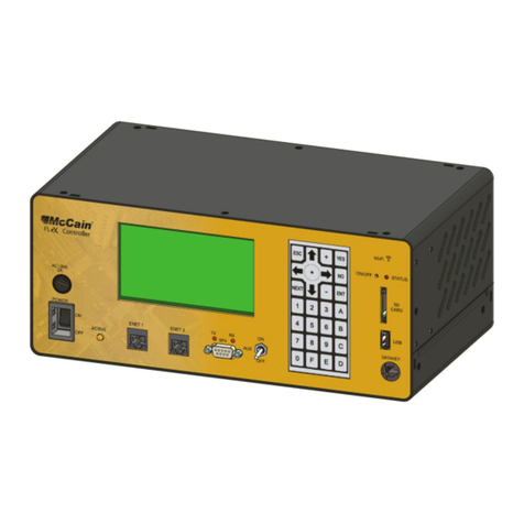
McCain ATC eX NEMA User manual

USER MANUAL
Version: 1.0
Product specifications: www.mccain-inc.com
Customer support: support@mccain-inc.com
Product Inquiries: 888-2-McCain (888-262-2246)
ATC eX NEMA
CONTROLLER

This page was intentionally left blank

Version
REVISIONS
Rev By Date Comments
1.0 GRubio 11/20/2010 Initial release

DISCLAIMERS
User Responsibility
This document is subject to revision. Users of this document are responsible for verifying the current
version status before using this document and or discarding all older revisions.
McCain Inc. shall not be liable for errors contained herein or for incidental or consequential damages in
connection with furnishing, performance or use of this material. MCCAIN MAKES NO WARRANTY OF
ANY KIND WITH REGARD TO THIS MATERIAL, INCLUDING, BUT NOT LIMITED TO, THE IMPLIED
WARRANTIES OF MERCHANTABILITY AND FITNESS FOR A PARTICULAR PURPOSE.
This document contains proprietary and confidential information and is the sole property of McCain. No
part of this document may be photo copied, reproduced, or translated to another language without the
prior written consent of McCain.
This manual is copyright © 2010 by McCain Inc. All rights reserved.
McCain Inc. // 2365 Oak Ridge Way // Vista, CA 92081
PH 760-727-8100
Product Specifications: www.mccain-inc.com
Product Inquiries: 888-2-McCain (888-262-2246)

McCain ATC eX NEMA Controller – User Manual i
Version 1.0
TABLE OF CONTENTS
1INTRODUCTION...................................................................................................................1
1.1Benefits .........................................................................................................................................1
1.2Controller features.........................................................................................................................1
2THE ATC eX NEMA CONTROLLER....................................................................................3
2.1Overview .......................................................................................................................................3
2.2Controller Operating System.........................................................................................................4
2.3Enclosure ......................................................................................................................................4
2.4Hardware Interfaces......................................................................................................................5
2.4.1Controller Front Panel...........................................................................................................5
2.4.1.1LCD with Backlight............................................................................................................5
2.4.1.2Contrast Knob ...................................................................................................................6
2.4.1.3Keypad..............................................................................................................................6
2.4.1.4Ethernet Ports ...................................................................................................................6
2.4.1.5USB Ports..........................................................................................................................6
2.4.1.6SDLC Port, SP-3...............................................................................................................6
2.4.1.7Port 2, SP-4, Terminal PC or General Purpose port.........................................................7
2.4.1.8SP-5 Port...........................................................................................................................7
2.4.1.9SP-8 Port...........................................................................................................................7
2.4.1.10Communications Modem Slot.......................................................................................7
2.4.1.11A2 Connector ................................................................................................................7
2.4.1.12Fuse and Switch............................................................................................................8
2.4.1.13Active LED.....................................................................................................................8
2.4.1.14Connector Box with A, B, C and D Connectors ............................................................8
2.5ATC eX NEMA Connectors Box....................................................................................................9
2.6Internal Construction / Sub-Assemblies:.....................................................................................11
2.6.1Power Supply Sub-Assembly (M45891).............................................................................11
2.6.2Control Signals Board Sub-Assembly (M66450A)..............................................................11
2.6.3Host Board Sub-Assembly (M69945A)...............................................................................12
2.6.4Engine Board Sub-Assembly (M69588A)...........................................................................13
2.6.5Modem Board Sub-Assembly (M66279A). .........................................................................14
2.6.6Internal Wiring.....................................................................................................................15
2.7Physical and Environmental Details:...........................................................................................16

ii
3CONFIGURATIONS............................................................................................................17
3.1TS2 Type 1..................................................................................................................................17
3.2TS2 Type 2..................................................................................................................................17
4CONTROLLER BOOT-UP..................................................................................................18
4.1Controller Follows Up the Next Boot Sequence:.........................................................................18
4.2Controller Storage Drives............................................................................................................22
5MAINTENANCE, ADJUSTMENTS AND TROUBLESHOOTING.......................................23
5.1Preventive Maintenance..............................................................................................................23
5.2Adjustment ..................................................................................................................................23
5.2.1Control Signals Board Adjustment......................................................................................23
5.2.2LCD Contrast Adjustment ...................................................................................................23
5.3Trouble Shooting Analysis ..........................................................................................................23
5.3.1DAT.....................................................................................................................................24
APPENDICES.............................................................................................................................25
A SCHEMATICS
B ASSEMBLY DRAWINGS
C BILL OF MATERIALS
D CONNECTORS’ DETAILS, FRONT PANEL
E CONNECTORS’ DETAILS, OPTIONAL CONNECTOR BOXES
F UPDATING KERNEL AND UBOOT

McCain ATC eX NEMA Controller – User Manual iii
Version 1.0
TABLE OF FIGURES
Figure 1: ATC eX NEMA controller...............................................................................................................2
Figure 2: Hardware Interfaces on the Front Panel........................................................................................5
Figure 3: Standard McCain option connector Box......................................................................................10
Figure 4: Traconex compatible option connector Box ................................................................................10

iv
This page was intentionally left blank

McCain ATC eX NEMA Controller – User Manual 1
Version 1.0
1 INTRODUCTION
The McCain’s ATC eX NEMA controller is an advanced, multi-application controller that simultaneously
supports multiple software applications through a single platform. Designed from the ground-up based on
NEMA TS-2 and ATC 5.2b standards, the ATC eX NEMA controller provides revolutionary flexibility and
control. Best of all, the single ATC eX compliant housing can be configured for either TS-2 Type 1 or TS-2
Type 2 applications and is backward compatible with TS-1. This allows end users to upgrade existing
intersections to a modern, high-performance platform without the need to replace cabinet hardware.
Built from the standards up, the controller is compliant with the latest NEMA and ATC standards.
The ATC eX features a wide variety of communications options, including serial and Ethernet, for
connectivity in any kind of environment. Quick data transfers, firmware upgrades, and log retrievals can
be done via USB.
The controller’s Linux operating system provides a robust, flexible, open-architecture platform that can support third
party applications.
1.1 Benefits
•NEMA TS-2 Type 1 and TS-2 Type 2 compatible.
•Compliant with current NEMA and ATC standards (Engine Board is fully compatible).
•Simultaneously supports multiple transportation software applications.
•Multi-tasking ability minimizes the amount of hardware required at intersections.
1.2 Controller features
Operating system: Linux.
Microprocessor: Freescale MPC8360 PowerQuicc II Pro microprocessor running at 400MHz.
Memory:
•16MB Flash memory
•128MB DDR2
•2MB Non-volatile SRAM
Backup real-time clock (RTC)
Applicable standards:
•NEMA TS-2 2003 v2.06
•ATC 5.2b

Controllers’ Interfaces:
Communication interfaces
•SDLC port (1) SP3 routed to NEMA TS-2 Port 1
•Serial (asynchronous) on front panel (3)
•Serial (asynchronous/synchronous) on 2070 compatible modem board slot (2)
•ENET 1: 100 Base-T Ethernet switch, 1 uplink and 3 additional ports
•ENET 2: 100 Base-T Ethernet port dedicated for local communications (i.e. laptop or similar)
•USB ports (4) with an internal USB hub
Front panel interface
•Display: 16 lines x 40 characters
•Keyboard: 7 x 4 keypad (28 key)
Cabinet interfaces
•NEMA TS-2 Type 1 Port 1 (SDLC), A2 connector
•NEMA TS-2 Type 2 A, B, C and D connectors
Figure 1: ATC eX NEMA controller
2

McCain ATC eX NEMA Controller – User Manual 3
Version 1.0
2 THE ATC eX NEMA CONTROLLER
2.1 Overview
The ATC eX NEMA controller unit is designed to meet TS2-2-2003 standard Ver 02.06,ATC 5.2b.
The controller unit uses an engine board fully compatible to ATC 5.2b standard; with the MPC8360 core
at 400MHz, 128MB DRAM, 16MB FLASH and 2MB SRAM.
All ATC eX NEMA controller’s interfaces to the cabinet, to other external devices, or to the user are
accessible from the front panel.
The unit has three RS-232 asynchronous serial communication ports with software selectable speed from
1.2Kbps to 115.2Kbps, these ports are available over DB-9 male connectors. PORT 2 is used primarily
for connecting a terminal computer, or as a general purpose port. SP-5 and SP-8 are general purpose
ports but only SP-8 has modem control lines (RTS, CTS, DCD).
An SDLC port is designated to synchronous communications to cabinet’s serial bus, it is a RS-485 serial
communication port with software selectable speed from 19.2Kbps to 614Kbps available over a DB-15
female connector.
A 2070 compatible modem or expansion slot is available to use SP-1 and SP-2 serial ports. This slot
works similar to 2070 controller slot A2.
Serial communications will be either synchronous or asynchronous depending on the type of board used
(2070-7A, 2070-7B, 2070-6A, 2070-6B, etc). Speed for this port is also software selectable from 1.2Kbps
to 115.2Kbps when it is operating on asynchronous mode and from 19.2Kbps to 614.4Kbps when it
operates on synchronous mode.
The unit also has 4 high speed USB ports to download and upload databases. These 4 ports are
connected directly to a USB hub and one port is routed to ATC Engine.
Two 100MBPS Ethernet ports are provided for communicating with a central, connecting to peripheral
devices, and also for operating as a remote terminal to download/upload files, updates, log files, etc.
The interface for the user is an LCD with backlight and a 28-keys keypad to enter/retrieve all information
about the status of the controller’s or traffic application. A contrast knob is used to adjust the contrast as
desired for user’s optimal view.
ACTIVE LED shows the status of the controller’s traffic application.
A circular connector A2 used to supply the AC input and fault monitor signals when required.
A rocker switch is used for turning ON and OFF the controller.
An AC line fuse holder for a 2A fuse with front access and removal without tools feature.
The functionality of the several modules/sub-assemblies which conform the controller unit is described in
the below sections.

4
2.2 Controller Operating System
The Operating system is Linux with kernel version 2.6.22.
After boot-up the ATC Linux OS is available to run applications and for accessing to the low level drivers
(block, character and network) provided by the kernel.
The OS is stored into a FLASH memory; this can be updated by using the Linux console or Ethernet
Ports.
A Linux console is configured at power up to a speed of 115.2Kbps, no parity, 8 bits and one stop bit.
For details on the operating system update refer to appendix F.
2.3 Enclosure
The ATC eX NEMA controller has a modular design with all hardware interface located at the front panel:
Power switch, fuse holder, serial ports’ connectors, Ethernet and USB connectors, LCD, contrast control,
keypad and ACTIVE LED indicator are accessible from the front of the unit.
The top cover of the ATC eX NEMA controller is closed and free of any vent or openings to avoid dirt,
dust, water or other debris entering from the top of the unit. Ventilation holes are provided on the sides of
the unit in order to cool the electronics; the design is such that foreign debris and water cannot easily
enter case under normal operation and handling.
The controller is constructed so that it can be shipped easily via common carrier, such as the postal
service, UPS, or Federal Express, without damage and without disassemble or removal of internal
components or subassemblies.

2.4 Hardware Interfaces
Figure 2: Hardware Interfaces on the Front Panel
2.4.1 Controller Front Panel
All ATC eX NEMA controller interfaces to the external world (cabinet, external devices, user) are
accessible from the front panel.
2.4.1.1 LCD with Backlight
The controller unit has a 16 lines X 40 Columns LCD display with LED backlight. This is the visual
interface of the user with the controller unit; through the different menus of the traffic application, it
displays current status, entered values and functions of the traffic application and other useful information
for the operation of the controller unit.
Character height is 0.2 inches.
The LCD backlight is turned on when any key from keypad is depressed and it will be extinguished after
60 seconds, this time can be programmed to be from 0 to 630 seconds.
The LCD operating range is fro –20°C to +70°C.
McCain ATC eX NEMA Controller – User Manual 5
Version 1.0

6
2.4.1.2 Contrast Knob
The CONTRAST knob adjusts the LCD display contrast for user’s optimum viewing. The LCD will appear
blank if knob while being completely clockwise and solid black if it is fully counterclockwise.
2.4.1.3 Keypad
The controller unit includes a 28 keys keypad to allow user for navigating and entering values to the
contents of the LCD menus.
The keys are identified as: ESC (escape), NEXT, ENT (enter), YES, NO, ARROW DOWN, ARROW UP,
ARROW RIGHT, ARROW LEFT; numbers 1, 2, 3, 4, 5, 6, 7, 8, 9 and 0; and letters A, B, C, D, E and F.
These keys allow the user to navigate thru the content of the LCD menus, confirm status, modify timing
parameters, setting date and time, configuring serial ports and all other interaction with the traffic
application.
2.4.1.4 Ethernet Ports
There are two Ethernet ports available on the front panel.
Port 1 is a 10/100 Base-T Ethernet switch with three RJ-45 jack connectors which can be used to handle
traffic applications needs, such us configuration, databases, etc.
Port 2 is a 10/100 Base-T Ethernet port with one RJ-45 jack connector; this port is intended to be used for
accessing to the controller’s operating system.
Each jack has two LED indicators to show the LINK ACT and 10-100 TX status.
2.4.1.5 USB Ports
Four hot-swappable USB connectors are located on front panel to allow the controller support the use of
USB memory devices for transferring data files from and to the controller; these data files can be firmware
upgrades, databases, etc.
2.4.1.6 SDLC Port, SP-3
It is located on front panel as a DB-15 female connector with latching blocks and it is labeled as
“SDLC”.
This port uses an SDLC communication protocol and four (Tx, Rx, TxClk and RxClk) EIA-485 differential
serial communications interfaces with a default speed of 153.6 Kbps in order to meet NEMA TS2-1998
specification.
The port has a software selectable speed of 19.2Kbps, 38.4Kbps, 57.6Kbps, 76.8Kbps, 115.2Kbps,
153.6Kbps and 614.4Kbps.
This port has a dedicated pin to disable all port communication when desirable; this is accomplished by
mating a connector to this port, in which pin 8 and pin 10 are connected (0VDC = Disabled).
This port is primarily dedicated to synchronous communications in a TS2 NEMA cabinet (BIU’s, MMU).
This port is connected to cabinet’s serial bus NEMA cabinet. The connection to the cabinet is thru a
SDLC communications cable connected to the SDLC port at one end and to the termination board on the

McCain ATC eX NEMA Controller – User Manual 7
Version 1.0
other end. Ensure a reliable connection by properly latching the spring latches onto the connector’s
latching blocks.
For port’s pin assignments see appendix D.
2.4.1.7 Port 2, SP-4, Terminal PC or General Purpose port
Port 2 is a general purpose port but it is primarily used for connecting a terminal and to perform data
transfer between the controller and an external computer.
It is located on front panel on a DB-9 male connector with jackscrews and it is labeled as Port 2. RTS,
CTS and DCD lines are not available on this port.
This port uses RS-232 asynchronous serial communications with a software selectable speed from
1.2Kbps to 115.2Kbps, with a default speed of 115.2Kbps.
For port’s pin assignments see appendix D.
2.4.1.8 SP-5 Port
SP-5 Port is a general purpose port; it is located on front panel on a DB-9 male connector with jackscrews
and it is marked as SP-5.
This port uses RS-232 asynchronous serial communications with software selectable speed from 1.2Kbps
to 115.2Kbps, with a default speed of 38.4Kbps.
For port’s pin assignments see appendix D.
2.4.1.9 SP-8 Port
SP-8 Port is a general purpose port; it is located on front panel on a DB-9 male connector with jackscrews
and it is marked as SP-8. This port uses RS-232 synchronous serial communications with software
selectable speed from 19.2Kbps to 614.4Kbps, with a default speed of 153.6Kbps.
For port’s pin assignments see appendix D.
2.4.1.10 Communications Modem Slot
SP-1 and SP-2 are general purpose ports and they are available on the communications slot at DIN96
connector.
The ports’ differential communications signals are used depending on the board plugged into the
communications slot (2070-7A, 2070-7B, 2070-6A, 2070-6B, etc); if the board is an asynchronous
communications board (such 2070-7A/6A/6B) the speed is software selectable from 1.2kBbps to
115.5Kbps, if the board is a synchronous communications board (2070-7B) the speed is software
selectable from 19.2Kbps to 614.4Kbps.
For port’s pin assignments see appendix D.
2.4.1.11 A2 Connector
This circular connector provides the AC connection (Line, neutral and chassis ground) and also the fault
monitor (FM) output. This connector is intended to be used when the controller is installed into NEMA
TS2 Type 1 cabinets.

8
2.4.1.12 Fuse and Switch
There is a fuse holder with a 2 amp fuse (3AG type) for the AC line located on the front panel which is
easily removed without using any tools. Also there is a rocker switch used to power on and off the
controller unit.
2.4.1.13 Active LED
This LED is used to indicate the status of the controller as defined for the application running into the
controller. When the application uses the voltage monitor and fault monitor signals, it must be changing
the status of this line in order to indicate that the controller is alive; if status does not change within a 2
seconds period then these lines are activated.
2.4.1.14 Connector Box with A, B, C and D Connectors
The ATC eX NEMA controller is a TS2 Type 1 controller that can be converted to a TS2 Type two
controller by adding an optional connector box in order to support the functionality of the A, B, C
connectors of the TS1 standard plus the special configuration D connector.
Currently there are two optional boxes, the Standard McCain connector Box and the Traconex compatible
box. The only one difference between them is the special configuration D connector.
Notes:
See appendix E for details on the pin assignments.
See “Configuration” section to see the details when attaching the box to the ATC eX NEMA controller.

McCain ATC eX NEMA Controller – User Manual 9
Version 1.0
2.5 ATC eX NEMA Connectors Box
Overview
In order to support all of the legacy hardware already implemented in the field, there is an optional
connector box for including the A, B and C connectors of a TS1 controller; D connector is a special
configuration connector that depends on the user needs or defined by the manufacturer.
This box converts the TS2 Type 1 controller into a TS2 Type 2 controller which supports the round
MilSpec connectors of the TS1 standard.
The controller uses an SPI bus in order to communicate to this box. Input and output pins use the NEMA
standard: 0 VDC = True, 24 VDC = False.
Currently there are two optional boxes that can be provided by McCain; the Standard McCain connector
Box and the Traconex compatible box. The only one difference between them is the special configuration
D connector.
See appendix E for details on the pin assignments.
Construction
The connector box consists of a chassis with a PCB assembly and harnesses for interconnecting it to the
controller. The PCB assembly contains all the circuitry and connectors for supporting the requirements of
the TS1 standard plus the required D connector.
The connectors A, B, C and D along with a fuse holder with a 24 VDC @ 1 A fuse are properly located
and labeled on the front of the box.
A three wires harness is used for receiving +24VDC, +5VDC and Logic Ground in order to feed all of the
I/O circuitry and supply the +24VDC to “A” connector for external use; the harness is attached to the
connector box and must be connected to the CONN BOX header located on Control Signals board
(M66450A).
A two wire harness is used for supplying AC power to the controller; it is attached to the connector box
and must be connected to the AC INPUT header located on Control Signals board (M66450A). A third
wire is used for connecting the chassis ground from the connector box to the chassis stud located on
controller.
A three wires harness is used for providing the Voltage Monitor (VM) and Fault Monitor (FM) signals from
the controller to the connector box; the harness is attached to the connector box and is connected to the
P1 header located on the Host board (M69945A).
A 10 position ribbon cable with plug connectors on both sides is used for the SPI communication between
the connector box and the controller; it is connected to the box on P7 header and to P9 header located on
the Host board (M69945A).

Figure 3: Standard McCain option connector Box
Figure 4: Traconex compatible option connector Box
Connector A
Connector A is a round, keyed connector with 55 male contacts.
Connector B
Connector B is a round, keyed connector with 55 female contacts.
Connector C
Connector C is a round, keyed connector with 61 female contacts.
Connector D
The pin assignment for this connector is not standard and it is defined by the manufacturer or depends on
the application needs.
On McCain option it is a round, keyed connector with 61 male contacts.
On Traconex compatible option it is a round, keyed, CPC connector with 63 male contacts.
See appendix E for details on the pin assignments.
10

McCain ATC eX NEMA Controller – User Manual 11
Version 1.0
2.6 Internal Construction / Sub-Assemblies:
This section briefly describes the construction and operation of each sub-assembly of the ATC eX NEMA
controller, indicating the interface connectors on each board and the relationship to the other boards.
For a more detailed understanding of a specific module or sub-assembly please refer to the proper
appendices.
Appendix A Contains all schematics.
Appendix B Contains the assembly drawings.
Appendix C Contains the bills of materials.
2.6.1 Power Supply Sub-Assembly (M45891).
This sub-assembly consists of a switching power supply module with a large can back up capacitor. It
provides the DC voltages to the Control Signals board (M66450A) and receives the AC power from such
board. The DC voltages provided are +24VDC, +12VDC and +5VDC.
2.6.2 Control Signals Board Sub-Assembly (M66450A).
This board generates the POWERDOWN, POWERUP and LINESYNC signals and along with the DC
voltages received from the power supply assembly. It also sends the signals and voltages to the other
sub-assemblies through the corresponding harness.
The board also defines the trip and recover window for the AC power input; this is a factory set
adjustment and should not be changed. The default is: 85VAC for power down and 90VAC for power up.
This sub-assembly contains the below circuits and connectors:
•A zero-crossing detector.
•Circuitry for generating the POWERDOWN, POWERUP and LINESYNC signals.
•An AC hysteresis trip/recover adjustment (POT1).
•A -12VDC power supply, it receives the +12VDC from the power supply sub-assembly (M45891)
and returns -12VDC to the P1 connector.
•A 12 positions connector (P1) for providing the DC voltages and control signals to the host board
(M69945A) and modem board (M66279A).
•A three positions header (CONN BOX) for providing the DC voltages for the optional connector
box.
•A five positions header (AC INPUT) for receiving the AC power input.***
•A three positions header (FUSE/SWITCH) for connecting the AC+ line to the fuse and switch
located on the front panel.
•A three positions header (AC OUTPUT) for providing the AC power to the power supply sub-
assembly (M45891).

12
•A five positions header (DC INPUT) for receiving the DC voltages from the power supply sub-
assembly (M45891).
*** The power input for this sub-assembly depends on the configuration chosen; it can receive the AC line
input either through the “A” connector resident on the optional connector box or from the front panel’s A2
connector (M44301).
2.6.3 Host Board Sub-Assembly (M69945A).
This sub-assembly supports almost all of the circuitry and physical connections of the communication
interfaces, as the name indicates, it is the host which supports the engine board, so that it contains all the
necessary circuitry to receive all communication channels, control lines from the engine and all the
necessary I/O interfaces to the external world. Below are briefly described the circuits and interfaces
included onto the host board:
•Two 50pos receptacle connectors to allow the Engine board to be plugged (P1 and P2).
•The +5VDC backup circuit.
•Voltage and Fault monitor driver circuit with a 3 positions header (P10) to plug front panel’s A2
connector harness plug.
•An ACTIVE LED driver circuit.
•A 12 position connector (P8) to receive DC voltages and control signals.
•A 10 position box connector (P9) to handle the SPI communication with the optional connector
box.
•A Header for a 10/100 Ethernet signal detection (J1).
•A 40 positions header (P3) for routing SP-1, SP-2, Ethernet, POWERUP and CPURESET signals
to the Modem board (M66279A).
•One D-sub 15 positions connector (CN2) for SDLC communications.
•Three D-sub 9 positions connectors (CN3, CN4, and CN5) for general purpose communications.
•Two Ethernet switches and four Ethernet jack connectors (RJ1A, RJ2A, RJ3A, RJ4A); one switch
handles three ports (RJ1A, RJ2A, RJ3A) on the front panel (Port 1) and another port routed to the
Modem board (M66279A) thru a ribbon cable (Port 4). The second switch handles one port
(RJ4A) on the front panel (Port 2) and three more ports located on a 40 position header box (P4).
•A USB switch and four USB connectors (USB1, USB2, USB3, USB4).
•An SPI EEPROM (U4) with factory set configuration parameters.
•A twenty positions header (P6) for attaching the LCD display.
•A three position header (P11) to plug the harness for LCD’s contrast control.
Table of contents
Other McCain Controllers manuals
Popular Controllers manuals by other brands
ProMinent
ProMinent DCM510 quick start guide

LNC
LNC Robot Series Operation and program manual
Phocos
Phocos CIS-MPPT 85/20 user manual
Bosch
Bosch AMC2 Series installation manual

Enovation Controls
Enovation Controls Murphy EMS PRO LITE Installation and operation manual
Emerson
Emerson Vilter Vission 20/20 Operation and service manual
