McCauley Sound M Series User manual

PARAMETER
PARAMETER
PARAMETER
PARAMETER
M Series Digital Processing Unit


McCauley Sound, Inc.
16607 Meridian Avenue East
Puyallup, Washington 98375 United States
Toll Free Number (877) McCauley
Direct Number (253) 848-0363
Fax (253) 841-3050
hp://www.mccauleysound.com
hp://www.linearray.com
Copyright © May 2008 McCauley Sound, Inc. All rights reserved. Informaon in this publicaon supersedes all
earlier versions. Specicaons subject to change.
AES standards are the sole property of the Audio Engineering Society and are available for a nominal fee from
the AES website hp://www.aes.org/standards.

RISK OF ELECTRIC SHOCK
DO NOT OPEN
TO REDUCE THE RISK OF ELECTRIC SHOCK, DO NOT
REMOVE COVER. NO USER SERVICEABLE PARTS INSIDE.
REFER SERVICING TO QUALIFIED SERVICE PERSONNEL.
TO REDUCE THE RISK OF FIRE OR ELECTRICAL SHOCK, DO
NOT EXPOSE THIS APPLIANCE TO RAIN OR MOISTURE.
TO REDUCE THE RISK OF FIRE, REPLACE ONLY WITH SAME
TYPE FUSE. REFER REPLACEMENT TO QUALIFIED SERVICE
PERSONNEL.
The exclamaon point within an equilateral
triangle is intended to alert the user to the
presence of important operang and
maintenance (servicing) instrucons in the
literature accompanying the product.
The lightning flash with arrowhead symbol
within an equilateral triangle is intended to alert
the user to the presence of uninsulated
“dangerous voltage” within the product’s
enclosure that may be of sufficient magnitude to
constute a risk of electric shock to persons.
:meaVcVi^dcd[<gVe]^XVaHnbWdah
SAFETY INSTRUCTIONS
READ THOROUGHLY BEFORE PROCEEDING
Read These Instructions
All safety and operang instrucons should be
read before the DPU is operated.
Keep These Instructions
The safety and operang instrucons should be
retained for future reference.
Heed All Warnings
All warnings on the product and in the operang
instrucons should be adhered to.
Do Not Use This Apparatus Near Water
The risk of electrical shock is greatly increased
when operated in a wet environment.
Clean Only With Dry Cloth
Unplug the DPU from the wall outlet before
cleaning using a damp cloth. Do not use liquid or
aerosol cleaners.
Do Not Attempt Self-Repair
Contact McCauley Sound Inc. when servicing is
required.
Do Not Defeat the Grounding Plug
If the provided plug does not t into your outlet,
consult an electrician for replacement of the
obsolete outlet.
Do Not Compromise the Power Cord
Protect the power cord from being walked on or
pinched parcularly at plugs, and the point where
they exit from the DPU.
Do Not Use Unsupported Components
Only use aachments and accessories provided by
McCauley Sound Inc.
Do Not Mount In Unstable Apparatus
If mounted improperly the DPU may fall, causing
serious bodily harm and serious hardware damage.
Do Not Block Any Ventilation Openings
Slots and openings in the DPU side are provided
for venlaon, to ensure reliable operaon and to
protect from overheang. These openings must not
be blocked or covered.
Keep this manual in a safe and accessible place for future reference.

CONTENTS
Features.................................................................................................................... 1
Contents of Kit.......................................................................................................... 1
Female RS232 DB-9 Connecon ............................................................................... 2
USB Connecon........................................................................................................ 2
Mute Buon ............................................................................................................. 2
Menu Buon ............................................................................................................ 2
Output Level LED ...................................................................................................... 3
Display Window........................................................................................................ 3
Rotary Thumb Wheel................................................................................................ 3
Menu Control Keys ................................................................................................... 3
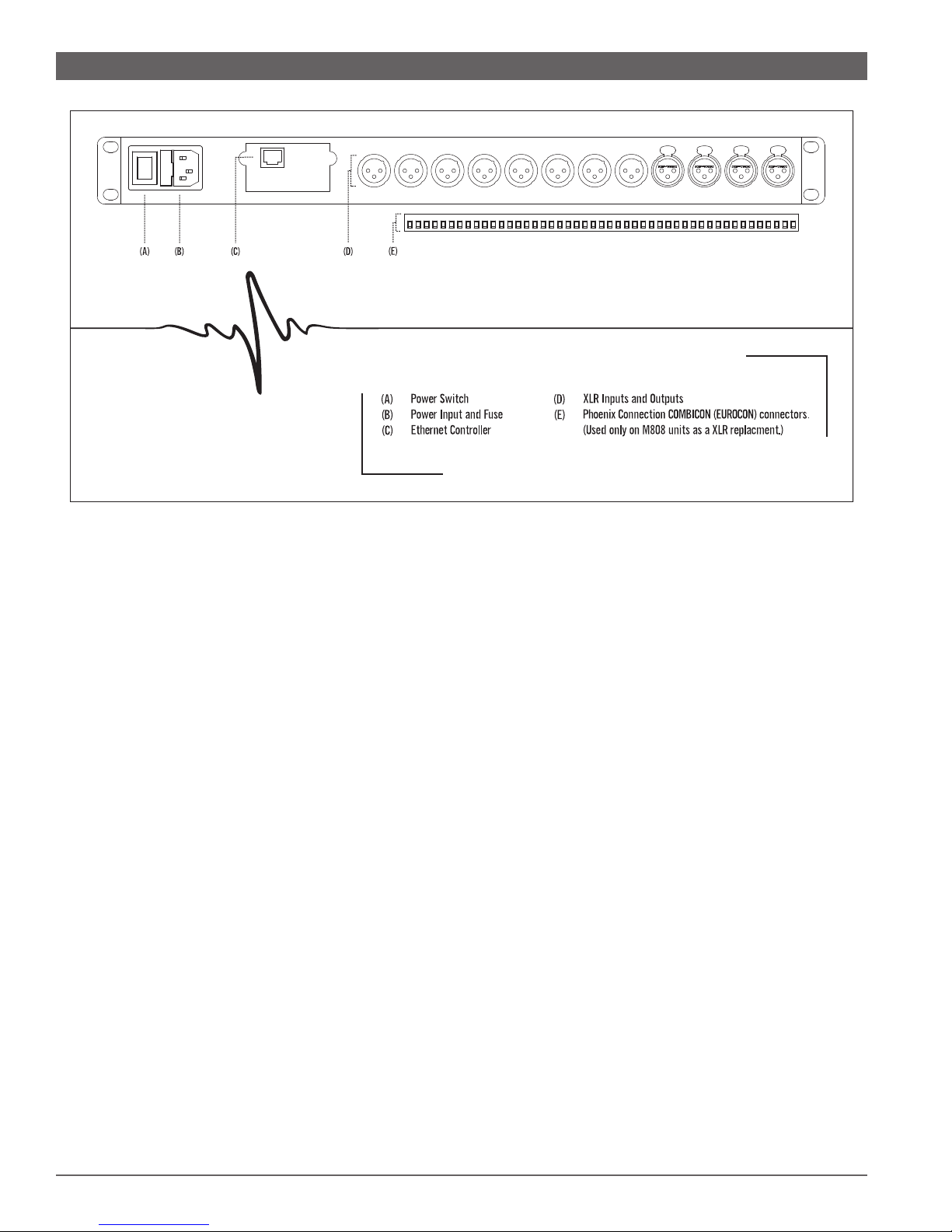
Main Power .............................................................................................................. 4
Main Fuse ................................................................................................................. 4
Power Switch ............................................................................................................ 4
Dierenal Input and Outputs ................................................................................. 4
A Note About Input Signal Levels ............................................................................. 4
Ethernet Control....................................................................................................... 5
Wireless Control ....................................................................................................... 5
Powering Up the Device ........................................................................................... 6
Signal – Signal Parameters ....................................................................................... 6
EQ – Parametric Equalizer Sengs .......................................................................... 7
GEQ – Graphic Equalizer Sengs ............................................................................. 7
XOver IIR – Crossover Parameters ........................................................................... 7
Comp – Compressor Parameters ............................................................................. 8
Name - Channel Name ............................................................................................. 9
Signal – Signal Parameters ....................................................................................... 9
EQ – Parametric EQ Sengs .................................................................................... 9
IIR – Crossover Parameters ...................................................................................... 10
FIR – Crossover Parameters ..................................................................................... 11
Limit – Limiter Parameters ....................................................................................... 11
Source – Input Mixer ............................................................................................... 11
Name – Channel Name ............................................................................................ 12
Recall - Preset Recall................................................................................................. 12
Store - Program Store ............................................................................................... 12

Cong - Device Conguraon ................................................................................... 12
Copy - Copy Channels............................................................................................... 13
General - General System Parameters ..................................................................... 13
Comm – Serial Communicaon Parameters............................................................. 14
FIR Taps – FIR Filter Taps Parameters........................................................................ 14
Ethernet – Ethernet Sengs ................................................................................... 15
Set PW – Set Password .......................................................................................... 15
Security - Security Locks ........................................................................................... 15
Appendix A - Screen Layout...................................................................................... 37
Appendix B - M808 Roung Matrix .......................................................................... 38
Appendix C - M408 Roung Matrix .......................................................................... 39
Appendix D - M306 Roung Matrix.......................................................................... 40
Appendix E - M204 Roung Matrix .......................................................................... 41
Appendix F - M808 Dimensions................................................................................ 42
Appendix G - M408 Dimensions ............................................................................... 43
Appendix H - M306 Dimensions ............................................................................... 44
Appendix I - M204 Dimensions ................................................................................ 45
Appendix J - XLR/Eurocon Diagram .......................................................................... 46

1
INTRODUCTION
The McCauley M Series line of Digital Processing Units have been engineered to meet the needs
and expectaons of the most demanding live sound and installaon environments. With a sleek
and space saving design, intuive front panel, and precise soware control, the M Series is well
equipped to provide the quality and performance you have come to expect from McCauley Sound.
400 MHz Analog Devices SHARC™ 21369 DSP
□
Extended 40-bit Arithmec for All Signal Operaons□
Up to 8 Inputs And 8 Outputs With Congurable Roung and Mixing Capability□
64-bit Internal Program and Data Memory Bus□
Dual Address Generators and Zero-Overhead DMA
□
96 kHz Sampling Rate□
24-bit Low Noise Analog to Digital and Digital to Analog Converters□
1 Hz Frequency Resoluon□
8 Parametric Equalizers on Each Input and Each Output□
31 Band Graphic Equalizer on Each Input□
Up to 48 dB/Octave IIR Crossover for Each Input and Output□
Up to 1200 Tap FIR Filters for Each Output□
Upgradable Firmware Through PC Connecon□
Storage for Up to 30 System Presets□
Each System Funcon Individually Lockable for Security□
XLR or EUROCON Analog Inputs and Outputs□
Serial, USB, and Ethernet for PC Control□
1 Sample 0.011ms Delay Capability Up to 650ms on Both Input and Output□
1 Digital Processing Unit□
1 IEC 60320 C13 Power Cord□
User Manual□

2
FRONT PANEL FEATURES
For serial communicaon, a standard male to female RS232 cable with
DB-9 connectors is required for connecng the DPU to a host PC.
The DPU features an internal USB to serial adapter that requires a USB cable
for connecon to the host PC. USB drivers are included with the McCauley DSP
console installaon: the drivers can be found under the installaon directory.
Input and output channels can be muted and un-muted by using the mute buon located beneath
each channel’s output level LED. When a channel is muted the buon will illuminate red.
Input and output channels can be selected by using the menu buon located beneath
each mute buon. When a channel is selected the buon will illuminate green. While
selected you are able to modify various parameters through the display window.
Linking mulple channels together is accomplished by pressing and holding the menu buon for
the rst channel. While sll holding down the rst buon, select the other channels. This eases
programming for the same parameters across mulple channels. Mulple inputs can be linked
together and mulple outputs can be linked together but inputs and outputs are linked separately.
PARAMETERPARAMETER

3
Each input and output has a ve segment LED for audio level display. The meter scale is factory
set so that 0 on the meter is 0dBu (0.775Vrms) and ranges from -20 through clipping.
A 4x26 character LCD shows all of the necessary informaon
for controlling the unit during operaon.
Parameter data values are changed by using the travel velocity sensing rotary thumb
wheel. The increment of adjustment varies in size based upon the speed and distance
of wheel rotaon. This aids in both small and large incremental data modicaons.
There are 6 menu keys:
Menu: ◄Previous menu.
Menu: ►Next menu.
Cursor: ◄ Previous cursor posion.
Cursor: ► Next cursor posion.
Enter: At the main menu enter can be used to open the system menu. Inside
the system menu, enter is used to proceed with selected acons.
Exit: Exit to the main menu.

4
REAR PANEL FEATURES
The DPU is powered by a low noise universal input power supply with an
operang range from 90VAC to 240VAC, 50-60Hz. Never defeat the grounding
on the DPU’s power supply; this could result in injury or death.
The power supply uses a slow blow type T2.5A-250V fuse. In the event of fuse failure,
always replace with the same type and rang fuse. If the fuse fails immediately aer
replacement, disconnue use of the DPU and contact McCauley Sound Support.
Controls power On/O.
The M204, M306, and M408 use AES14-1992 standard XLR connecons. The M808 uses Phoenix
Connecon 1754562 MSTB 2.5/ 8-ST COMBICON (EUROCON) connectors. Inputs and outputs
are electronically precision balanced to obtain maximum common mode rejecon. To prevent
signicant signal loss when an unbalanced signal is used, consult Appendix E for connecon
recommendaons. It is strongly recommended that balanced signals be used whenever possible.
There is no analog gain adjustment on the M Series DPU, all the processing (including
gain) is performed digitally. As a consequence of this, it is important to supply the
processor with the opmum signal level to achieve good signal to noise performance as

5
well as adequate headroom before clipping. The DPU is designed to clip at signal levels
above +20dBu (7.75Vrms) which places the noise oor below -90dBu. The opmum
input signal level to supply a M Series processor is 0dBu (.775Vrms). This input level will
allow 20dB of headroom while keeping the signal >90dB above the noise oor.
The DPU features a 10/100 auto switching controller connected to an industry standard
RJ-45 port. The controller will also auto detect crossover cables to simplify installaon.
The M Series DPU can be controlled wirelessly by connecng it to a wireless gateway and
then using the McCauley DSP Console on a computer aached to the same network.

6
DEVICE OPERATION
Aer powering up the unit, the following inializaon screen is displayed on the LCD:□
The inializaon process takes about 8 seconds. During □
that period the unit boots and displays the DPU rmware version.
Aer the inializaon process is nished the DPU displays its main screen:□
The screen shows the current program number and program name
□
assigned to the unit. The DPU always returns to the state it was in when power was
removed.
INPUT MENUS
LEVEL□Sets the signal gain from -40.00dB to +15.00dB in steps of 0.25dB.
POL□Polarity can be normal (+) or inverted (-).
DELAY□A maximum of 650ms (62400 steps) in 21us steps. Units
of delay can be changed in the system menu to milliseconds, feet, or meters.

7
EQ#□Selects one of the 8 available parametric equalizers.
TYP□ Type of equalizer: peak/notch (PEQ), Low-Shelf (LO-SHF),
High-Shelf (HI-SHF), or All Pass (AP-1, AP-2).
FRQ
□Equalizer center frequency ranges from 20Hz to 30,000Hz in either 1Hz or
1/36 octave steps. The frequency steps can be changed in the system menu.
BW□ Equalizer bandwidth ranges from 0.02 to 2.50 octaves in steps of 0.01. The
Q value automacally updates. Low-Shelf or High-Shelf can be either 6 or
12dB/Oct.
LVL□Equalizer gain ranges from -30.00dB to +15.00dB in steps of 0.25dB.
BYP□ Enable/Disable EQ secon.
GEQ□Selects one of the 31 available equalizer bands.
LEVEL□Equalizer gain ranges from -30.00dB to +15.00dB in steps of 0.25dB.
BYPASS□ Enable/Disable EQ Secon.
HPF□ High pass lter type: Buerworth (Buttwrth), Linkwitz-Riley (Link-Ri),
or Bessel.
FQHP□ High pass lter cut-o frequency ranges from 20Hz to 30,000Hz in either
1Hz steps or 1/36 octave steps. The frequency steps can be selected in the
system menu.
SLHP□ High pass lter slope ranges from 6dB/Oct. to 48dB/Oct. in 6dB steps for
Buerworth/Bessel and 12dB steps for Linkwitz-Riley.

8
LPF□ Low pass lter type: Buerworth (Buttwrth), Linkwitz Riley (Link-Ri),
or Bessel.
FQLP□ Low pass lter cut-o frequency ranges from 20Hz to 30,000Hz in either
1Hz steps or 1/36 octave steps. The frequency steps can be selected in the
system menu.
SLLP□ Low pass lter slope ranges from 6dB/Oct. to 48dB/Oct. in 6dB steps for
Buerworth/Bessel and 12dB steps for Linkwitz-Riley.
Filter Conguraon Low Crossover Point High Crossover
Point
None HPF O LPF O
Highpass HPF On LPF O
Lowpass HPF O LPF On
Bandpass HPF On LPF On
THRESH□Limit threshold ranges from -20 to +20dBu in steps of 0.5dB.
ATTACK□ Aack me ranges from 0.3 to 1ms in steps of 0.1ms, and from 1 to
100ms in steps of 1ms.
RELEASE□ Release me can be 2X, 4X, 8X, 16X or 32X the aack me.
RATIO□ Compression rao ranges from 1:40 to 1:1.

9
Name□Channel name can be up to 6 characters in length.
OUTPUT MENUS
LEVEL□Sets the signal gain from -40.00dB to +15.00dB in steps of 0.25dB.
POL□Polarity can be normal (+) or inverted (-).
DELAY□A maximum of 650ms (62400 steps) in 21us steps. Units
of delay can be changed in the system menu to milliseconds, feet, or meters.
EQ#□Selects one of the 8 available parametric equalizers.
TYP□ Type of equalizer: peak/notch (PEQ), Low-Shelf (LO-SHF),
High-Shelf (HI-SHF), or All Pass (AP-1, AP-2).
FRQ□Equalizer center frequency ranges from 20Hz to 30,000Hz in either 1Hz or
1/36 octave steps. The frequency steps can be changed in the system menu.
BW□ Equalizer bandwidth ranges from 0.02 to 2.50 octaves in steps of 0.01. The
Q value automacally updates. Low-Shelf or High-Shelf can be either 6 or
12dB/Oct.
LVL□Equalizer gain ranges from -30.00dB to +15.00dB in steps of 0.25dB.
BYP□ Enable/Disable EQ secon.

10
HPF□ High pass lter type: Buerworth (Buttwrth), Linkwitz-Riley (Link-Ri),
or Bessel.
FQHP□ High pass lter cut-o frequency ranges from 20Hz to 30,000Hz in either
1Hz steps or 1/36 octave steps. The frequency steps can be selected in the
system menu.
SLHP□ High pass lter slope ranges from 6dB/Oct. to 48dB/Oct. in 6dB steps for
Buerworth/Bessel and 12dB steps for Linkwitz-Riley.
LPF□ Low pass lter type: Buerworth (Buttwrth), Linkwitz Riley (Link-Ri),
or Bessel.
FQLP
□ Low pass lter cut-o frequency ranges from 20Hz to 30,000Hz in either
1Hz steps or 1/36 octave steps. The frequency steps can be selected in the
system menu.
SLLP□ Low pass lter slope ranges from 6dB/Oct. to 48dB/Oct. in 6dB steps for
Buerworth/Bessel and 12dB steps for Linkwitz-Riley.
Filter Conguraon Low Crossover Point High Crossover
Point
None HPF O LPF O
Highpass HPF On LPF O
Lowpass HPF O LPF On
Bandpass HPF On LPF On

11
ENHP□ Enable/Disable high pass.
ENLP□ Enable/Disable low pass.
FRHP□ High pass lter cut-o frequency ranges from 20Hz to 30,000Hz in either
1Hz steps or 1/36 octave steps. The frequency steps can be selected in the
system menu.
FRLP□ Low pass lter cut-o frequency ranges from 20Hz to 30,000Hz in either
1Hz steps or 1/36 octave steps. The frequency steps can be selected in the
system menu.
Note: The slope is set by the allocang lter taps in the system menu.
THRESH□Limiter threshold ranges from -20 to +20dBu in steps of 0.5dB.
ATTACK□ Aack me ranges from 0.3 to 1ms in steps of 0.1ms, and from 1 to
100ms in steps of 1ms.
RELEASE□ Release me can be 2X, 4X, 8X, 16X or 32X the aack me.
1,2,3,4□Input channel source for the current output channel. If more than one
input source is enabled, they are added together to form the output.

12
Name□Channel name can be up to 6 characters in length.
SYSTEM MENUS
The system menu allows the user to control and change parameters that are related to the
system’s behavior and general operaon. It can be accessed by pressing the enter key at the main
menu. All system menus require the enter key to be pressed to conrm the selected acon.
The DPU has memory to store up to 30 dierent program setups. A program
can be recalled using this menu, overwring any current conguraon.
PROG
□Program number to be recalled.
NAME□Program name.
A program can be stored using this menu, overwring any program already saved under the
selected number. Once the program is stored in ash memory, it can be recalled at a later me.
PROG□ Program number under which to store the current conguraon.
NAME□Program name up to 12 characters in length.
A pre-dened input/output conguraon can be selected using this menu.
Crossover point parameters such as lter type, cut-o frequency and slope
are not aected and have to be congured manually for each Output.
These conguraons are not saved in memory during shutdown.

13
MODE□ Changes the mode of operaon.
Mode: Out 1 Out 2 Out 3 Out 4 Out 5 Out 6
None Any Any Any Any Any Any
Stereo 2-Way In 1 In 1 In 2 In 2 Any Any
Stero 3-Way In 1 In 1 In 1 In 2 In 2 In 2
Copy channel parameters from a source channel to a target channel(s). When
the source and target(s) are either inputs or outputs, all audio parameters will
be copied. When either the source or the target is an input while the other is an
output, only the level, polarity, delay and parametric EQ sengs are copied.
SOURCE
□Channel to be copied from.
TARGET□Channel to be copied to.
FREQ MODE□ Selects the frequency increment for EQ and crossover sengs, 36
steps/octave or all frequencies (1 Hz resoluon).
DELAY UNIT□Milliseconds (ms), feet (ft), or meters (m).

14
BAUD RATE□ Select the baud rate for serial communicaon.
DEVICE #□ Assigns the device ID from 1 to 16, when used in single master
mulple slave (SMMS) serial conguraons.
FIR lter slope steepness is controlled by allocang space for coecients. The DPU contains
a total of 1600 memory locaons for all of the outputs. Use this page to allocate memory
based on your applicaon. Exceeding 1600 lter taps can lead to unexpected behavior.
□1 to 8 Select the order for output FIR lters in 50 tap steps. The sum of all
taps cannot exceed 1600.
Filter Order Minimum
Frequency(Hz)
50 4800
100 2400
150 1600
200 1300
250 1000
300 850
350 700
400 625
450 550
500 500
550 450
600 425
650 400
700 390
750 385
800 340
This manual suits for next models
4
Table of contents
Popular Recording Equipment manuals by other brands

OTARI
OTARI MX-5050 instruction manual

Philips
Philips VoiceTracer VTR8062 user manual

TourCraft
TourCraft MINI25 user manual

Comunello Automation
Comunello Automation GINDEXSTN0B00A Installation and user manual

Mitsubishi Electric
Mitsubishi Electric DX-TL4509E series user manual

Illumra
Illumra E3X-232FP installation guide