herdstar BinTrac HouseLINK HL-10PLV User manual

Installation and Operation Manual
HouseLink™ HL-10P(LV)
12/5/2022
Installation and Operation Manual
HouseLink HL-10P(LV)

Installation and Operation Manual
HL-10P(LV) Installation Manual Ver 1.0 2Part Number MAN-000024
Table of Contents
Description ..............................................................................................................................................................................3
Installation...............................................................................................................................................................................3
Setup & Configuration.............................................................................................................................................................3
Dip Switch Setup.................................................................................................................................................................3
BinTrac Indicator Setup.......................................................................................................................................................4
Operation.................................................................................................................................................................................4
Status LEDs ........................................................................................................................................................................4
Testing & Calibration...........................................................................................................................................................4
Output Specification................................................................................................................................................................5
Operational Specifications ......................................................................................................................................................6
Addendum A............................................................................................................................................................................7
Addendum A –Wiring Diagram...........................................................................................................................................8
is a registered trademark of HerdStar, LLC.
Copyright © 2022 HerdStar, LLC. All rights reserved.
Printed in the USA
1400 Madison Avenue Suite 504, Mankato, MN 56001
PH: 507-344-8005 FAX: 507-344-8009
www.herdstar.com

Installation and Operation Manual
HL-10P(LV) Installation Manual Ver 1.0 3Part Number MAN-000024
Description
The House Link HL-10P Low Voltage (LV) provides a 2mV/V or 3mV/V output proportional to the weight of the selected
bin. The device will connect to the BinTrac Indicator BINS port in parallel with the Smart Summing Box. The BinTrac
Indicator transmits digital weight data which is converted to a proportionate millivolt output.
Installation
The HouseLink HL-10P(LV) is designed to be used with the BinTrac Bin Weighing system. One HouseLink HL-10P(LV)
can be connected per displayed bin.
1. The HouseLink HL-10P(LV) should be mounted no more than 10
feet from the house control.
2. Using a two-conductor cable (ordered separately), connect the
green wire from the Smart Summing Box (or the BINS port on the
BinTrac Indicator) to the +COM (OUT) terminal in the HouseLink
HL-10P(LV) and the white wire from the Smart Summing Box (or
the BINS port on the BinTrac Indicator) to the -COM (OUT)
terminal in the HouseLink HL-10P(LV). See Figure 1.
3. Connect the HouseLink HL-10P(LV) to the house control by
connecting the +EXC (IN) to the + EXC terminal and the
–EXC (IN) to the –EXC terminal of the house control.
4. Finally, connect the +mV/V (OUT) from the HouseLink HL-10P(LV)
to the + SIG of the house control and the –mV/V from the HouseLink
HL-10P(LV) to the –SIG of the house control.
Setup & Configuration
Dip Switch Setup
The unit has four dip switches that need to be set up for configuration (circled in Figure 2).
Bin Selection (S1 and S2)
This setting allows you to control which bin the HL-10P(LV)
will send data from (see below). By default, S1 and S2 are
both in the OFF position (Bin A).
ZERO Tracking (S3)
This setting allows the ZERO to be tracked with the BinTrac
Indicator. Setting S3 to the ON position will allow the ZERO
to be tracked by the house controls. By default, dip switch S3
is in the OFF position.
Output Scale Selection (S4)
This setting provides a 3mV/V output at full scale. Setting S4 to the ON position will instead provide a 2mV/V at full scale.
By default, dip switch S4 is in the OFF position.
A B C D
Figure 1
Figure 2
Figure 1
Installation and Operation Manual
HL-10P(LV) Installation Manual Ver 1.0 4Part Number MAN-000024
BinTrac Indicator Setup
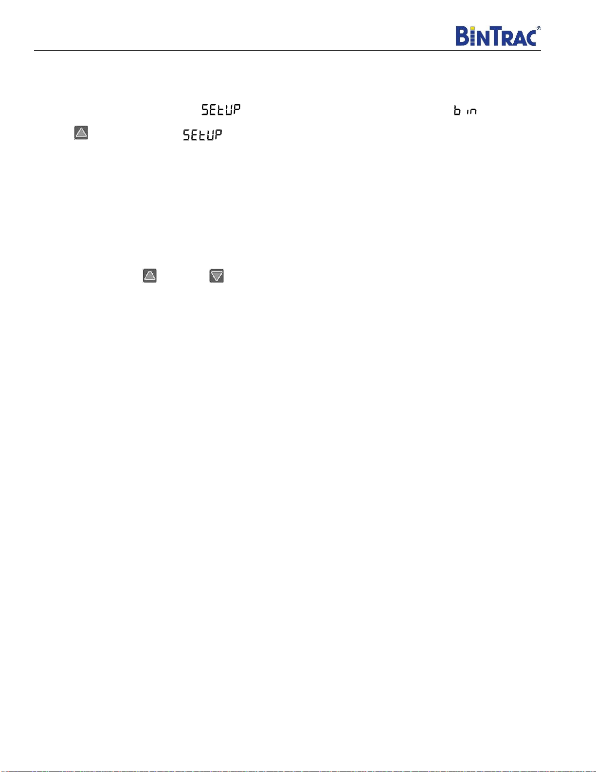
The BinTrac Indicator must be set up for peripheral devices. Access the SETUP menu on the BinTrac Indicator by
pressing and holding the BIN key until appears, then release. If the display changes to , press the
UPPER key once to return to .
The Bin LEDs indicate configuration options as being enabled (solid on) or disabled (flashing).
Bin A –Configures BinTrac Monitor as a Remote Display.
Bin B –Enable ASCII Serial Communications Command Set
Bin C –Enable Weight Broadcast.
Bin D –Enable communications to peripheral devices.
This must be enabled when BinTrac Indicator is connected to the HouseLink HL-10P(LV).
1. Press the BIN key to select the desired configuration option.
2. Use the UPPER or LOWER keys to enable or disable options.
Operation
Status LEDs
The LED will flash three different ways dependent upon how the unit is operating.
SLOW FLASH –This indicates the unit is communicating and operating normally.
FAST FLASH –This means the unit is in Test mode.
STEADY ON –This indicates the unit is not communicating but has power.
NO LIGHT –The unit doesn’t have an adequate power source.
Testing & Calibration
Once the unit is wired and the dip switches are set up correctly, the unit can be put into one of five test modes. These
modes are useful when setting up and testing with the house controls.
Please note: Due to increased filtering effects on house controllers, for best calibration results wait thirty
seconds after each button press on the HL-10P so weights can stabilize before proceeding further in the
calibration process.
Test 1 –Press the Test button on the board once and the unit will output -0.5 mV/V.
Test 2 –Press the Test button on the board twice and the unit will output 0 mV/V.
Test 3 –Press the Test button on the board three times and the unit will output 2 mV/V.
Test 4 –Press the Test button on the board four times and the unit will output 3 mV/V.
Test 5 –Press the Test button on the board five times and the unit will output 4.5 mV/V.
Pressing the test button a sixth time will return the unit to normal operations. If the unit is left in test mode, it will
automatically return to normal operation mode after five minutes.
*For calibrating the HouseLink HL-10P(LV) with a Maximus-Systems control, please refer to instructions in Addendum A.

Installation and Operation Manual
HL-10P(LV) Installation Manual Ver 1.0 5Part Number MAN-000024
Output Specification
The displayed weight is relative to the output voltage from the HouseLink HL-10P(LV). The charts below outline the
percentage of the total weight based on the output voltage.
mV/V
% of Total
Weight
-1.00
-75
-1.00
-50
0.00
0
1.00
50
2.00
100
3.00
150
4.00
200
4.50
225
4.50
250
mV/V
% of Total
Weight
-1.00
-75
-1.00
-33.3
0.00
0
1.00
33.3
2.00
66.6
3.00
100
4.00
133.33
4.50
150
4.50
175
-1.00
-1.00
0.00
1.00
2.00
3.00
4.00
4.50
4.50
-2.00
-1.00
0.00
1.00
2.00
3.00
4.00
5.00
-100 0100 200 300
mV/V Output
%of Total Weight
2mV/V Output
mV/V
-1.00
-1.00
0.00
1.00
2.00
3.00
4.00
4.50
4.50
-2.00
-1.00
0.00
1.00
2.00
3.00
4.00
5.00
-100 -50 050 100 150 200
mV/V Output
%of Total Weight
3mV/V Output
mV/V

Installation and Operation Manual
HL-10P(LV) Installation Manual Ver 1.0 6Part Number MAN-000024
Operational Specifications
Operating Temperature Range: -40°C to +60°C (-40°F to +140°F)
Humidity: 5% to 95% (non-condensing)
Environmental Air: No corrosive gasses permitted
Shock and Vibration: N/A
Enclosure Type: Unsealed
Agency Approvals: N/A
Wiring Type: Screw terminal block
Power Requirements: 2.25 VDC –2.75 VDC, 70 mA (max)
Output Signal Type: Simulates 3mV/V 360 ohm load cell.
Maximum Output Signal Range: -1.0 mV/V to +4.5 mV/V
Default Output Value: -1.0 mV/V
Maximum Load Capacitance: No limit
Zero Accuracy: +/- 35 mV/V
Span Accuracy: +/- 0.2% of reading
Linearity Error: +/- 0.02% of full-scale
Span Temperature Stability: +/- 35 ppm/°C
Output Signal Resolution: .092 mV/V
Output Signal Ripple: .046 mV/V
Serial Communication Interface Type: HerdStar optically isolated (proprietary)

Installation and Operation Manual
HL-10P(LV) Installation Manual Ver 1.0 7Part Number MAN-000024
Addendum A
Initial Setup of the Maximus Control using the HouseLink Proportional Interface HL-10P(LV)
The HouseLink Proportional Interface HL-10P(LV) emulates a bin scale allowing the user to connect a BinTrac bin scale
system to a Maximus control. An individual HouseLink HL-10P(LV) control is required for each bin that is being
connected to the Maximus. The HouseLink HL-10P(LV) is a highly accurate unit that simplifies the calibration with the
Maximus without the need of filling the bin with known weight amount or the bin being empty. Setup can be completed
with material in the bin.
1. Locate the HouseLink HL-10P(LV) in a dry location near the Maximus control.
2. The Maximus Bin brains unit is required for interfacing bin weights to the Maximus.
3. Wire the BinTrac indicator, Smart Summing Box, HouseLink HL-10P(LV), and the Maximus per the wiring
diagram.
4. Calibrate the Bintrac Indicator so it is accurately weighing the bin. See BinTrac manuals.
5. Set HouseLink HL-10P(LV) dipswitches S1 & S2 for the desired bin that it will emulate to the Maximus.
6. Set HouseLink HL-10P(LV) dipswitch S3 to OFF for weight readings on the Maximus to match the BinTrac
following zeroing.
7. The Maximus Brain is made to work with 2mv/v. Set the S4 dip switch in the HouseLink HL-10P(LV) to the
UP/ON position. This sets the output at 2mV/V which matches the Maximus Brain.
8. The BinTrac indicator needs to be set up for peripheral devices. Follow the procedure shown in the HouseLink
HL-10P(LV) “Installation and User Guide”.
9. Calibrate the Maximus control using the calibration method for empty and full weight and using the HouseLink HL-
10P(LV) test mode to output an empty and full weight simulated weight reading. *Please note: Due to increased
filtering effects on house controllers, for best calibration results wait thirty seconds after each button
press on the HL-10P so weights can stabilize before proceeding further in the calibration process.
a. Enter the calibration mode on the Maximus control.
b. Press the TEST button on the HouseLink HL-10P(LV) two times for the 0mV/V output setting which
represents an empty bin weight reading.
c. Calibrate Maximus to the empty bin weight reading and advance to known weight reading.
d. Press the HouseLink HL-10P(LV) TEST button 1 more time for the 2mV/V output setting which represents
a full capacity bin weight reading.
e. Enter the BinTrac Load Cell Capacity setting as the known weight value in the Maximus control. Ex: For
a BinTrac scale system with six 10k load cells this would be 60,000lbs load cell capacity.
f. Calibration of Maximus control to the BinTrac system should be completed.
g. Press HouseLink HL-10P(LV) TEST button three more times to exit test mode. HouseLink HL-10P(LV)
will now output the correct mV/V to the Maximus that will match the BinTrac Indicator’s displayed weight.
10. Verify the displayed weight of the BinTrac Indicator closely matches the displayed weight on the Maximus control.
Note: It may take a minute or more for the Maximus control to begin displaying the correct amount. If weight
values are not within 50lbs, repeat step 9.

Installation and Operation Manual
HL-10P(LV) Installation Manual Ver 1.0 8Part Number MAN-000024
Addendum A –Wiring Diagram
This manual suits for next models
1
Table of contents
Other herdstar Recording Equipment manuals


