McConnel Twose Series Application guide

Twose Series
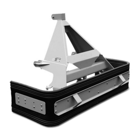
Front Mounted Furrow Press
Fixed & Folding Models
Operation & Parts Manual
Publication 722 (May 2016) Part No. 22675.22

IMPORTANT
VERIFICATION OF WARRANTY REGISTRATION
DEALER WARRANTY INFORMATION & REGISTRATION VERIFICATION
It is imperative that the selling dealer registers this machine with McConnel Limited before
delivery to the end user – failure to do so may affect the validity of the machine warranty.
To register machines go to the McConnel Limited web site at www.mcconnel.com, log
onto ‘Dealer Inside’ and select the ‘Machine Registration button’which can be found in
the Service Section of the site. Confirm to the customer that the machine has been
registered in the section below.
Should you experience any problems registering a machine in this manner please contact
the McConnel Service Department on 01584 875848.
Registration Verification
Dealer Name:
……………………..…………………………………………………………….
Dealer Address:
…….………………………………………………………………………….
Customer Name:
……………………..…………………………………………………………
Date of Warranty Registration:
……/……/...…… Dealer Signature: ………………..……
NOTE TO CUSTOMER / OWNER
Please ensure that the above section above has been completed and signed by the selling
dealer to verify that your machine has been registered with McConnel Limited.
IMPORTANT: During the initial ‘bedding in’ period of a new machine it is the customer’s responsibility
to regularly inspect all nuts, bolts and hose connections for tightness and re-tighten if required. New
hydraulic connections occasionally weep small amounts of oil as the seals and joints settle in – where
this occurs it can be cured by re-tightening the connection – refer to torque settings chart below.The
tasks stated above should be performed on an hourly basis during the first day of work and at least
daily thereafter as part of the machines generalmaintenance procedure.
CAUTION: DO NOT OVER TORQUE HYDRAULIC FITTINGS AND HOSES
TORQUE SETTINGS FOR HYDRAULIC FITTINGS
HYDRAULIC HOSE ENDS PORT ADAPTORS WITH BONDED SEALS
BSP
Setting
Metric
BSP
Setting
Metric
1/4” 18 Nm 19 mm 1/4” 34 Nm
19 mm
3/8” 31 Nm 22 mm 3/8” 47 Nm
22 mm
1/2” 49 Nm 27 mm 1/2” 102 Nm
27 mm
5/8” 60 Nm 30 mm 5/8” 122 Nm
30 mm
3/4” 80 Nm 32 mm 3/4” 149 Nm
32 mm
1” 125 Nm 41 mm 1” 203 Nm
41 mm
1.1/4”
190 Nm
50 mm
1.1/4”
305 Nm
50 mm
1.1/2” 250 Nm 55 mm 1.1/2” 305 Nm
55 mm
2” 420 Nm 70 mm 2” 400 Nm
70 mm


Warranty Policy (page 1 of 3)
WARRANTY POLICY
WARRANTY REGISTRATION
All machines must be registered, by the selling dealer with McConnel Ltd, before delivery to the end user.
On receipt of the goods it is the buyer’s responsibility to check that the Verification of Warranty
Registration in the Operator’s Manual has been completed by the selling dealer.
1. LIMITED WARRANTIES
1.01. All mounted machines supplied by McConnel Ltd are warranted to be free from defects in material
and workmanship from the date of sale to the original purchaser for a period of 12 months, unless a
different period is specified.
All Self Propelled Machines supplied by McConnel Ltd are warranted to be free from defects in
material and workmanship from the date of sale to the original purchaser for a period of 12 months
or 1500 hours. Engine warranty will be specific to the Manufacturer of that unit.
1.02. All spare parts supplied by McConnel Ltd and purchased by the end user are warranted to be free from
defects in material and workmanship from the date of sale to the original purchaser for a period of 6
months. All parts warranty claims must be supported by a copy of the failed part invoice to the end
user. We cannot consider claims for which sales invoices are not available.
1.03. The warranty offered by McConnel Ltd is limited to the making good by repair or replacement for the
purchaser any part or parts found, upon examination at its factory, to be defective under normal use
and service due to defects in material or workmanship. Returned parts must be complete and
unexamined. Pack the component(s) carefully so that any transit damage is avoided. All ports on
hydraulic items should be drained of oil and securely plugged to prevent seepage and foreign body
ingress. Certain other components, electrical items for example, may require particular care when
packing to avoid damage in transit.
1.04. This warranty does not extend to any product from which McConnel Ltd’s serial number plate has
been removed or altered.
1.05. The warranty policy is valid for machines registered in line with the terms and conditions detailed and
on the basis that the machines do not extend a period of 24 months or greater since their original
purchase date, that is the original invoice date from McConnel Limited.
Machines that are held in stock for more than 24 months cannot be registered for warranty.
1.06. This warranty does not apply to any part of the goods, which has been subjected to improper or
abnormal use, negligence, alteration, modification, fitment of non-genuine parts, accident damage,
or damage resulting from contact with overhead power lines, damage caused by foreign objects (e.g.
stones, iron, material other than vegetation), failure due to lack of maintenance, use of incorrect oil or
lubricants, contamination of the oil, or which has served its normal life. This warranty does not apply
to any expendable items such as blades, belts, clutch linings, filter elements, flails, flap kits, skids, soil
engaging parts, shields, guards, wear pads, pneumatic tyres or tracks.
1.07. Temporary repairs and consequential loss - i.e. oil, downtime and associated parts are specifically
excluded from the warranty.
1.08. Warranty on hoses is limited to 12 months and does not include hoses which have suffered external
damage. Only complete hoses may be returned under warranty, any which have been cut or repaired
will be rejected.
1.09. Machines must be repaired immediately a problem arises. Continued use of the machine after a
problem has occurred can result in further component failures, for which McConnel Ltd cannot be held
liable, and may have safety implications.
1.10. If in exceptional circumstances a non McConnel Ltd part is used to effect a repair, warranty
reimbursement will be at no more than McConnel Ltd’s standard dealer cost for the genuine part.

Warranty Policy (page 2 of 3)
1.11. Except as provided herein, no employee, agent, dealer or other person is authorised to give any
warranties of any nature on behalf of McConnel Ltd.
1.12. For machine warranty periods in excess of 12 months the following additional exclusions shall apply:
1.12.1. Hoses, exposed pipes and hydraulic tank breathers.
1.12.2. Filters.
1.12.3. Rubber mountings.
1.12.4. External electric wiring.
1.12.5. Bearings and seals
1.12.6. External Cables, Linkages
1.12.7. Loose/Corroded Connections, Light Units, LED’s
1.12.8. Comfort items such as Operator Seat, Ventilation, Audio Equipment
1.13. All service work, particularly filter changes, must be carried out in accordance with the manufacturer’s
service schedule. Failure to comply will invalidate the warranty. In the event of a claim, proof of the
service work being carried out may be required.
1.14. Repeat or additional repairs resulting from incorrect diagnosis or poor quality previous repair work
are excluded from warranty.
NB Warranty cover will be invalid if any non-genuine parts have been fitted or used. Use of non-genuine
parts may seriously affect the machine’s performance and safety. McConnel Ltd cannot be held
responsible for any failures or safety implications that arise due to the use of non-genuine parts.
2. REMEDIES AND PROCEDURES
2.01. The warranty is not effective unless the Selling Dealer registers the machine, via the McConnel web
site and confirms the registration to the purchaser by completing the confirmation form in the
operator’s manual.
2.02. Any fault must be reported to an authorised McConnel Ltd dealer as soon as it occurs. Continued use
of a machine, after a fault has occurred, can result in further component failure for which McConnel
Ltd cannot be held liable.
2.03. Repairs should be undertaken within two days of the failure. Claims submitted for repairs undertaken
more than 2 weeks after a failure has occurred, or 2 days after the parts were supplied will be
rejected, unless the delay has been authorised by McConnel Ltd. Please note that failure by the
customer to release the machine for repair will not be accepted as a reason for delay in repair or
submitting warranty claims.
2.04. All claims must be submitted, by an authorised McConnel Ltd Service Dealer, within 30 days of the
date of repair.
2.05. Following examination of the claim and parts, McConnel Ltd will pay, at their discretion, for any valid
claim the invoiced cost of any parts supplied by McConnel Ltd and appropriate labour and mileage
allowances if applicable.
2.06. The submission of a claim is not a guarantee of payment.
2.07. Any decision reached by McConnel Ltd. is final.
3. LIMITATION OF LIABILITY
3.01. McConnel Ltd disclaims any express (except as set forth herein) and implied warranties with respect to
the goods including, but not limited to, merchantability and fitness for a particular purpose.
3.02. McConnel Ltd makes no warranty as to the design, capability, capacity or suitability for use of the
goods.
3.03. Except as provided herein, McConnel Ltd shall have no liability or responsibility to the purchaser or
any other person or entity with respect to any liability, loss, or damage caused or alleged to be caused
directly or indirectly by the goods including, but not limited to, any indirect, special, consequential, or
incidental damages resulting from the use or operation of the goods or any breach of this warranty.
Notwithstanding the above limitations and warranties, the manufacturer’s liability hereunder for
damages incurred by the purchaser or others shall not exceed the price of the goods.
3.04. No action arising out of any claimed breach of this warranty or transactions under this warranty may
be brought more than one (1) year after the cause of the action has occurred.

Warranty Policy (page 3 of 3)
4. MISCELLANEOUS
4.01. McConnel Ltd may waive compliance with any of the terms of this limited warranty, but no waiver of
any terms shall be deemed to be a waiver of any other term.
4.02. If any provision of this limited warranty shall violate any applicable law and is held to be
unenforceable, then the invalidity of such provision shall not invalidate any other provisions herein.
4.03. Applicable law may provide rights and benefits to the purchaser in addition to those provided herein.
McConnel Limited

DECLARATION OF CONFORMITY
Conforming to EU Machinery Directive 2006/42/EC
We,
McCONNEL LIMITED, Temeside Works, Ludlow, Shropshire SY8 1JL, UK
Hereby declare that:
The Product; Tractor Mounted Front Presses
Product Code; TFMP
Serial No. & Date ………………………………… Type …………………………
Manufactured in; United Kingdom
Complies with the required provisions of the Machinery Directive 2006/42/EC
The machinery directive is supported by the following harmonized standards;
■BS EN ISO 12100 (2010) Safety of machinery –General principles for design –Risk
assessment and risk reduction.
■BS EN 349 (1993) + A1 (2008) Safety of machinery - Minimum distances to avoid the
entrapment with human body parts.
■BS EN ISO 14120 (2015) Safety of machinery - Guards general requirements for the
design and construction of fixed and movable guards.
■BS EN 4413 (2010) Hydraulic fluid power. Safety requirements for systems and their
components.
McCONNEL LIMITED operates an ISO 9001:2008 quality management system,
certificate number: FM25970.
This system is continually assessed by the;
British Standards Institution (BSI), Beech House, Milton Keynes, MK14 6ES, UK
BSI is accredited by UK Accreditation Service, accreditation number: UKAS 003.
The EC declaration only applies if the machine stated above is used in
accordance with the operating instructions.
Signed …………………................ Responsible Person
CHRISTIAN DAVIES on behalf of McCONNEL LIMITED
Status: General Manager Date: January 2018

LIST OF CONTENTS
Operator Section
General Information 1
Machine Description 2
Machine Identification 2
Specifications 3
Safety Information 4
General Instructions 7
Machine Attachment 8
Machine Removal 9
Parts Section
FP1530 Assembly 12
FP1545 Assembly 14
FP3030 Assembly 16
FP3045 Assembly 19
FPF3030 Assembly 20
FPF3045 Assembly 22
FP4030 Assembly 24
FP4045 Assembly 26
FPF4030 Assembly 28
FPF4045 Assembly 30
Hydraulic Rams 32
Hydraulic Installation Kit 33


1
GENERAL INFORMATION
Always read this manual before fitting or operating the machine – whenever any doubt
exists contact your dealer or the McConnel Service Department for advice and assistance.
Use only McConnel Genuine Service Parts on McConnel Equipment and Machines
DEFINITIONS –The following definitions apply throughout this manual:
WARNING
An operating procedure, technique etc., which –
can result in personal injury or loss of life if not observed carefully.
CAUTION
An operating procedure, technique etc., which –
can result in damage to either machine or equipment if not observed carefully.
NOTE
An operating procedure, technique etc., which –
is considered essential to emphasis.
LEFT AND RIGHT HAND
This term is applicable to the machine when attached to the tractor and is viewed
from the rear – this also applies to tractor references.
MACHINE & DEALER INFORMATION
Record the Serial Number of your machine on this page and always quote this number when
ordering parts. Whenever information concerning the machine is requested remember also to state
the make and model of tractor to which the machine is fitted.
Machine Serial Number: Installation Date:
Machine Model details:
Dealer Name:
Dealer Address:
Dealer Telephone No:
Dealer Email Address:

2
Machine Identification Plate
MACHINE DESCRIPTION & PURPOSE OF USE
The Furrow Press is a machine designed for fitting to the 'Front Mounted' tractor linkage
only. The purpose for which the machine is intended is to prepare ploughed land to seed
bed standards.
When used on land that has been ploughed ready for cultivation, the Furrow Press (fitted
to the front linkage of tractor) together with a Cultivator/Combination Seed Drill (fitted to
the rear linkage of tractor) can produce a total cultivating unit which will cultivate and seed
the land in a ‘one-pass’ operation.
The Front Furrow Press width for 'one pass' operation should be chosen to match the
width of the rear mounted Seed Drill.
The attachment of the Furrow Press to the front linkage of the tractor is the same system
as generally used for rear mounted three point linkage implements, namely; 2 lower link
arms plus an adjustable central top link arm.
The smaller (narrower) press machines are of a fixed width design, and the larger
machines (up to 4m) are of a design that uses three frame sections; main centre frame
plus 2 wings. Wings are operated by hydraulic rams allowing them to be raised and
lowered into position.
Press rings are available in a choice of either 30° or 45° angles, the angle chosen will be
determined by preferential choice and the specific land conditions - they have to give good
clod breaking action and produce a below surface preparation.
MACHINE IDENTIFICATION
Each machine is fitted with an identification plate with the following information:
1. Machine (Part Number)
2. Machine Serial No.
3. Machine Weight
When ordering spares or replacement parts from your
local dealer it is important to quote both Part Number
and Serial Number as stated on the identification plate
so the machine and model can be quickly and correctly
identified.

3
SPECIFICATIONS
Fixed Models
Model Working Width Length Height Ring Profile Weight
FP1530 1.5m (4'11") 1.3m (4'3") 1.37m (4'6") 30° 863kg
FP1545 1.5m (4'11") 1.3m (4'3") 1.37m (4'6") 45° 936kg
FP3030 3.0m (9'10") 1.3m (4'3") 1.37m (4'6") 30° 1430kg
FP3045 3.0m (9'10") 1.3m (4'3") 1.37m (4'6") 45° 1660kg
FP4030 4.0m (13'1") 1.3m (4'3") 1.37m (4'6") 30° 1760kg
FP4045 4.0m (13'1") 1.3m (4'3") 1.37m (4'6") 45° 2000kg
Folding Models
Model Working Width Length (*) Height (*) Ring Profile Weight
FPF3030 3.0m (9' 10") 1.3m (4'3") 1.37m (4'6") 30° 1480kg
FPF3045 3.0m (9' 10") 1.3m (4'3") 1.37m (4'6") 45° 1670kg
FPF4030 4.0m (13'1") 1.3m (4'3") 1.37m (4'6") 30° 1760kg
FPF4045 4.0m (13'1") 1.3m (4'3") 1.37m (4'6") 45° 2000kg
(*) unfolded

4
SAFETY INFORMATION
DANGER
Never attempt to assemble, couple up, or operate machinery until you
understand fully the functions, controls and safety precautions required, as
shown in the operator’s manual.
DANGER
Always follow and adhere to tractor safety operations and instructions
carefully. Never take risks and never leave tractor seat whilst the engine or
machine is running.
CAUTION
Be aware of all warning and instruction decals on machine as care must be
taken and instructions obeyed.
CAUTION
Contact your dealer should you need advice, assistance, or if you do not
understand the manual or machine. Never assume; if you are unsure...ask.
CAUTION
The machine must not be altered or modified in any way without permission.
No liability will be accepted in respect of a machine that has been modified
without the manufacturers’ permission.
DANGER
Never drive machinery at speeds that could cause danger to other persons or
properties, or in a manner that may cause accidents.
DANGER
Never attempt to service, adjust, or work on any machinery in an unsupported
state; ensure that all machinery is safely supported and propped using
suitable equipment.
DANGER
Always ensure that the wheels of a wheeled implement/machine are
'chocked' firmly to ensure there is no risk of the implement moving before
attempting any service or maintenance work on it.
CAUTION
Always ‘switch off’ the tractor engine and remove the starting key before
attempting to carry out inspections, repairs or service on the machine.

5
DANGER
Always be aware of your surroundings and operate machinery accordingly.
Beware of confined tight areas, low height restrictions, buildings and
overhangs etc. Also drive and operate bearing in mind weather conditions
such as sun, rain, ice, snow, and wind etc. - Make allowances in all situations.
CAUTION
Never operate machine in a reckless or uncaring manner. Respect other road
users and be patient.
CAUTION
Never carry passengers on machinery or tractor. Ensure bystanders/onlookers
are kept well away from operational area of the machinery.
CAUTION
Never climb underneath an unsupported or suitably propped machine for any
reason, especially if the unit is still operating. Never rely on tractor hydraulics
to raise and support a machine for service or maintenance. Always use
suitable equipment specifically designed for the task.
CAUTION
Always select a firm level site for parking, removal or storage of the machine.
Chock and prop the machine to ensure it is left in a safe and secure state.
Ensure that all stand legs on the machine are correctly locked into position.
CAUTION
Never allow children to play on or around parked or stored machinery.
CAUTION
Never wear loose fitting or ragged clothing which could get caught up in
machinery or on controls.
CAUTION
Ensure visibility is clear through cab-screens at all times.
CAUTION
Always dispose of discarded or worn out parts thoughtfully by disposing of
them in an approved and specified legal scrap site, bin or skip.
CAUTION
Worn out and spent waste oil, grease and other obnoxious substances must
always be disposed of in suitable and legally approved dumping containers
suitable for the waste in question.

6
Highway Use
When operating machinery on the Highways the ‘Local Highways Department’ should be
consulted for approval and notification as rules and regulations vary from local authority
area to area. Highways Department regulations must be followed.
Have respect for 'passing' traffic and keep 'passing' lane free from obstruction.
Allow time for walkers and cyclists to clear site.
When using on the Highway consult the 'Lighting Regulations' for correct procedures.
Transport Speed
The acceptable speed of transport will vary greatly depending upon the ground conditions.
In any conditions avoid driving at a speed which causes exaggerated bouncing as this will
put unnecessary strain on the tractors top hitch position.
When transporting the machine on the highway it is important that transport speed be kept
to a low sensible figure (12-15mph maximum).

7
GENERAL INSTRUCTIONS
1. Always select a firm level site for attachment and removal of the machine to the tractor.
2. Ensure bystanders are kept at a safe distance from all machinery during the
attachment procedure.
3. When manoeuvring the tractor ensure there are no persons in the close vicinity - make
known your intentions and keep a look out at all times when reversing and aligning up
to the machine for ‘coupling up’.
4. Always secure tractor into selected position by ensuring that brakes are applied
correctly.
5. Make sure that the lift arms and top link ball ends of the tractor are properly fitted to the
machine/implement by using correct adapter sleeves where necessary, and that
retaining pins of the correct type are used on all three point linkage points. Secure pins
with relevant pin and ring assembly.
6. Should it be necessary to make any adjustments or service on the machine whilst it is
raised on the tractor linkage, trestles or suitable supports must be positioned to support
machine to prevent accidental dropping of the lift arms or mechanical failure; the
machine must always be ‘propped and chocked’.
7. Never attempt to repair, adjust or service machinery of any kind whilst it is still running
or working. Always stop the machine and stop the tractor engine before any
service/repairs begin. Switch off tractor engine before leaving the tractor seat.
8. In transit always use transport stays or locking devices where provided.
9. If required, ensure the tractor is suitably ballasted in order to maintain stability of the
unit.
10.Always use machines in a sensible and reasonable manner and do not attempt to use
them in work for which they are not intended. Avoid overloading and abusing them as
this can cause damage to machine and tractor and can be very dangerous.
11.When unhitching/detaching a machine from a tractor three point linkage ensure that
any stands or legs are securely positioned and that the machine is parked where it will
not be a safety hazard or cause annoyance to others. Ensure that the chosen parking
site is firm and level.
12.Carry out regular periodic maintenance to ensure the machine continues to perform
correctly and safely. Ensure regular maintenance procedures are maintained for the
lifetime of the machine.
Health and Safety Rules and Regulations relating to Agricultural Machinery must
be respected at all time.

8
ATTACHING THE MACHINE
Ensure machine is parked on a firm and level site. Keep all bystanders at a safe distance.
1. Remove spring pins and lift pins (supplied with the machine) from lower link positions
of linkage frame.
NOTE: On applications using automatic quick ‘crook-on’ lower links, the lower link balls
and eyes will need to be assembled on the lift pins and re-attached to the lower
connection points on the machine’s frame.
2. Slowly and carefully drive the tractor forward towards the machines linkage frame.
Pin Type Connections only
3. Ensure that tractor lower link ball eyes fit between lower jaws of linkage frame and that
pin holes are aligned.
4. Fit linkage/lift pins through both sides of machine to couple the tractor lower link arms
to lift position and secure pins in position with lynch pins.
Crook-on Type Connections only
3. Ensure that tractor lower link crooks are positioned directly below the pin and ball
assemblies on the machines lift positions.
4. Slowly raise the tractor’s lift arms to a position where the balls engage correctly within
their housings on the lift arms.
All Connections Types
5. Connect top link assembly between the machine and the tractor’s top link position,
secure at both ends by fitting top link pins and secure with lynch pins.
6. Adjust top link by turning its central tube to give a length that allows the machine to be
level when lifted.
7. Raise machine on the linkage to a height that will permit removal of the stand legs;
remove legs and refit them upside-down in their stowed position, secure in place with
security pins provided.
Hydraulic Models only
8. Couple-up the machine’s hydraulic hoses for operation of the hydraulic rams to the
tractor’s auxiliary supply, use extension hoses if required. Operate the rams to ensure
they are functioning correctly.

9
REMOVING THE MACHINE
Ensure machine is parked on a firm and level site. Keep all bystanders at a safe distance.
1. Raise tractor front linkage to position the machine at a height that will allow the stand
legs to be fitted.
2. Remove the stand legs from their stowed locations and replace them in their support
positions, secure in place with pins provided.
3. Lower the machine slowly until the stand legs are resting on the ground.
It may be necessary to adjust the top link to ensure the machine is resting on all legs.
4. Remove the top link assembly and store in a safe location.
Hydraulic Models only
5. Disconnect hydraulic hoses from the tractor’s auxiliary system. Stow the hose neatly in
a location where they will not foul on components when parting the tractor from the
machine.
Pin Type Connections only
6. Remove lower link pins.
Crook-on Type Connections only
6. Release the catches on the tractor’s lower links and carefully lower the link arms to
separate the link arms from the pin and ball assemblies.
All Connections Types
7. Slowly and carefully reverse the tractor away from the machine.
8. Replace linkage pins into their relevant holes for safe keeping.
9. Carefully check to ensure that the machine is left in a safe, stable condition.
Machine Storage
For extended periods of storage it is advisable that the machine be kept in a clean dry
environment protected from the elements to avoid risk of corrosion.
The machine should be thoroughly cleaned and lubricated prior to storage. At this point it
is good practice to check the machine for worn or damaged components - any parts that
require replacing should be ordered and fitted at the earliest opportunity so the machine is
fully prepared for the next seasons work.

10

11
FRONT MOUNTED
FURROW PRESS
(Fixed & Folding Frame Models)
Generic Parts Manual
Generic parts manuals should be used as a general guide to the components used on the
machine; to ensure accurate parts information for a specific machine please refer to the
‘Interactive Parts Database’ on our website which identifies the exact components used on
the machine when it was manufactured based on the machine’s unique serial number.
Direct access can be gained using the web address or QR code below.
http://www.mcconnel.com/support/product-support/interactive-parts-database/
If an interactive search yields no results please contact the McConnel Parts Dept. for information.
Tel: +44 (0)1584 873131
Other manuals for Twose Series
3
This manual suits for next models
10
Table of contents
Other McConnel Power Tools manuals
