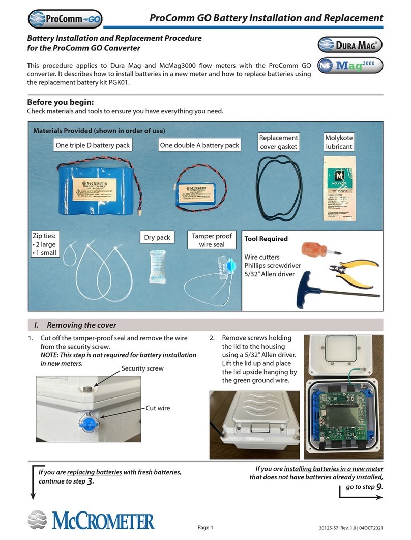
McCrometer ProComm HL User manual

ProComm
Electromagnetic
Flow Meter Converter
30124-60 Rev. 1.2
December 16, 2019
ProComm
Installation, Operation and
Maintenance Manual
www.mccrometer.com
Standard Model
For use in non-hazardous locations
HL Model
For use in hazardous locations:
• Class I, Division 2, Groups A-D, T5
• Class I, Zone 2 IIC T5

Table of Contents
SAFETY.....................................................................................1
Safety Symbols ................................................................................... 1
Safety Warnings .................................................................................. 1
1.0 CONVERTER DESCRIPTION .............................................................2
2.0 INSTALLING THE CONVERTER AND CABLES .............................................2
2.1 Verify Serial Numbers .................................................................... 2
2.2 Mounting the Converter .................................................................. 3
2.3 Installing Cables through Cable Glands and Conduit ....................................... 4
2.4 Cable Gland Assignment for Wiring Harnesses ............................................. 5
2.5 Pulling Sensor Cable Through Electrical Conduit ........................................... 6
3.0 CONNECTING WIRES TO TERMINALS . . . . . . . . . . . . . . . . . . . . . . . . . . . . . . . . . . . . . . . . . . . . . . . . . . . . 7
3.1 Terminal Block Diagram .................................................................. 7
3.2 Wiring Diagrams ......................................................................... 8
3.3 4-20mA Hook-Up ........................................................................ 9
3.4 Opto-Isolated Pulse Output Hook-Up ....................................................10
3.5 Opto-Isolated Input . . . . . . . . . . . . . . . . . . . . . . . . . . . . . . . . . . . . . . . . . . . . . . . . . . . . . . . . . . . . . . . . . . . . . 10
3.6 Optional Smart Output Hook Up .........................................................11
3.7 Converter Power Wiring Diagram ........................................................11
4.0 CONVERTER OPERATION..............................................................12
4.1 Starting up the Converter ...............................................................12
4.2 Menu Navigation .......................................................................12
4.3 Front Panel Display .....................................................................13
4.4 Menu Structure .........................................................................15
4.5 Factory Set Key Code ....................................................................16
4.6 Converter Access Code ..................................................................16
4.7 Changing Settings on the Quick Start Menu ..............................................17
4.8 Changing Main Menu Settings ...........................................................18
5.0 MENU DESCRIPTIONS ................................................................19
5.1 Menu 1 - Sensor ........................................................................19
5.2 Menu 2 - Units ..........................................................................21
5.3 Menu 3 - Scales .........................................................................22
5.4 Menu 4 - Measure .......................................................................24
5.5 Menu 5 - Alarms ........................................................................26
5.6 Menu 6 - Inputs .........................................................................27
5.7 Menu 7 - Outputs .......................................................................29
5.8 Menu 8 - Communication ................................................................31
5.9 Menu 9 - Display ........................................................................32
5.10 Menu 10 - Data Logger ..................................................................32
5.11 Menu 11 - Functions.....................................................................35
5.12 Menu 12 - Diagnostic....................................................................35
5.13 Menu 13 - System .......................................................................36
6.0 BIV (BUILT-IN VERIFICATION) ..........................................................37
6.1 Functioning ............................................................................37
6.2 Saving Reference Values (Characteristic Parameters) ......................................37
6.3 Criteria and Internal Limits Values........................................................37
6.4 General Notes for the Activation of BIV ...................................................37
6.5 ISOBIV Interface ........................................................................38
7.0 ERROR CODES........................................................................39
8.0 ALARM MESSAGES ...................................................................40
9.0 SPECIFICATIONS .....................................................................42
10.0 DIMENSIONS.........................................................................44
11.0 RETURNING A UNIT FOR REPAIR .......................................................46
12.0 TROUBLESHOOTING GUIDE ...........................................................47
WARRANTY STATEMENT ....................................................................48
30124-60 Rev. 1.2 | 16DEC2019
Page ii

When installing, operating, and maintaining McCrometer equipment where hazards may be present, you must protect
yourself by wearing Personal Protective Equipment (PPE) and be trained to enter conned spaces. Examples of conned
spaces are manholes, pumping stations, pipelines, pits, septic tanks, sewage digesters, vaults, degreasers, storage tanks,
boilers, and furnaces.
SAFETY
Safety Symbols
Throughout this manual are safety warning and caution information boxes. Each warning and caution box will be identied
by a large symbol indicating the type of information contained in the box. The symbols are explained below:
Safety Warnings
!
i
This symbol indicates important safety information. Failure to follow the instructions can
result in serious injury or death.
This symbol indicates important information. Failure to follow the instructions can result in
permanent damage to the meter or installation site.
WARNING!
Pressurized pipes should only be hot tapped, cut, or drilled by qualied personnel. If possible,
depressurize and drain the pipe before attempting any installation.
At the end of its lifetime, this product shall be disposed of in full compliance with the
environmental regulations of the state in which it is located.
!
!
!
!
!
!
WARNING!
Incorrect installation or removal of FPI Mag meters can result in serious injury or death. Read the
instructions in this manual on the proper procedures carefully.
WARNING!
Never enter a conned space without testing the air at the top, middle, and bottom of the space. The
air may be toxic, oxygen decient, or explosive. Do not trust your senses to determine if the air is safe. You
cannot see or smell many toxic gases.
WARNING!
Never enter a conned space without the proper safety equipment. You may need a respirator, gas de-
tector, tripod, lifeline, and other safety equipment.
WARNING!
Never enter a conned space without standby/rescue personnel within earshot. Standby/rescue
personnel must know what action to take in case of an emergency.
WARNING!
Carefully read all safety warning tags attached to the meter.
30124-60 Rev. 1.2 | 16DEC2019
Page 1
SAFETY
ProComm

1.0 CONVERTER DESCRIPTION
Read this entire manual prior to installation and/or changing any settings. Retain this manual in your records, DO NOT
DISCARD.
The signal converter is the reporting, input and output control device for the sensor. The converter allows the measurements,
functional programming, control of the sensor and data recording to be communicated through the display and inputs
& outputs. The microprocessor-based signal converter has a multi-point curve-tting algorithm to improve accuracy,
dual 4-20mA analog outputs, an RS485 communication port, an 8-line graphical backlit LCD display with six-key touch
programming, and a rugged enclosure that meets IP67. In addition to a menu-driven self-diagnostic test mode, the
microprocessor continually monitors the converter's functionality. The converter will output rate of ow and total volume.
The converter also comes standard with password protection and many more features.
2.0 INSTALLING THE CONVERTER AND CABLES
2.1 Verify Serial Numbers
The converter and sensor are supplied as a matched system. Verify the meter serial numbers on both the converter and
sensor match. This will ensure a properly calibrated system.
The tag on the side of the converter has the converter model Number, the converter serial number, the converter model
number and the sensor model number. An example is shown below as Figure 1.
Figure 1. Converter Serial Number Tag
IMPORTANT: Verify the meter serial numbers on both the converter and sensor match. This will ensure
a properly calibrated system. The meter serial number is located on the side of the sensor, and the
converter serial number and the meter serial number are located on a label on the side of the converter.
Ensure the meter serial number on the sensor and the converter tags match.
i
Meter mount converter Remote mount converter
30124-60 Rev. 1.2 | 16DEC2019
Page 2
CONVERTER DESCRIPTION
ProComm

2.2 Mounting the Converter
Note: This applies to the remote mount converter only.
If possible, mount the converter in an electronics shed or environmental enclosure. The sun shield should be oriented in a
direction to reduce sun damage and ensure readability.
Mount the converter to a solid surface using four bolts (Figure 2) or to a vertical or horizontal post using two clamps (Figure
3 and Figure 4). This electronic unit is rated IP67 for temporary ooding.
Figure 2. Mounting converter to solid surface
Figure 3. Mounting converter to vertical post
Figure 4. Mounting converter to horizontal post
Remove brackets, reverse them,
and reattach as shown.
If the brackets are not attached,
attach them with the four screws.
Mount the converter to a solid surface with four bolts through the
holes in the left and right brackets.
Remove brackets, reverse them,
and reattach as shown.
Open clamps and attach around post. Slide bracket tabs onto clamps
and tighten them.
Open clamps and attach around post. Slide bracket tabs onto clamps
and tighten them.
30124-60 Rev. 1.2 | 16DEC2019
Page 3
INSTALLING THE CONVERTER AND CABLES
ProComm

2.3 Installing Cables through Cable Glands and Conduit
All electrical cables enter the converter through compression ttings or optional customer-supplied conduit located on the
side or bottom of the converter (Figure 5, Figure 6, Figure 7) . Ensure that all compression glands are properly tightened and
all unused ttings are plugged so the case remains sealed.
The power cable and wiring harnesses are each assigned specic cable glands where they will pass through into the
converter. See section 2.4 for cable gland assignment for wiring harnesses and section 3.2 for wiring diagrams.
All cable compression glands must be properly tightened to prevent moisture intrusion and maintain the IP67 rating. To
insure IP67 rating, use only round cable 0.24" to 0.47" in diameter.
Figure 5. Remote mount
converter with ve cable
gland pass-throughs
Figure 6. Remote mount converter
with three conduit pass-throughs
The remote mount converter is shipped with ve 1/2" NPT cable glands.
Up to three cable glands may be removed and replaced with 1/2" conduits.
Figure 7. Meter mount
converter with three cable
gland pass-throughs
IMPORTANT: Do not cut or alter the cable
length on power or signal cables!
Connections to the sensor must be made with
cable supplied by McCrometer specically for
that purpose. Do not substitute the supplied cable with
other types of cable, even for short runs. For repairs or
added lengths of cable, the entire cable between the sensor
and the converter must be replaced. (Consult factory for
replacement cable.)
i
!Attaching conduit directly to the enclosure may
introduce dangerous gasses and moisture into
the enclosure creating a dangerous condition,
and will remove the enclosure's IP67 rating.
Damage caused by attaching conduit to the enclosure or
altering the enclosure in any way is not covered by the
warranty.
30124-60 Rev. 1.2 | 16DEC2019
Page 4
INSTALLING THE CONVERTER AND CABLES
ProComm

Figure 9. Remote mount converter cable assignments
Figure 8. Meter mount converter cable assignments
2.4 Cable Gland Assignment for Wiring Harnesses
To prevent signal interference and to keep the wiring organized, each cable gland is assigned for a specic wiring harness.
Refer to the assignment diagrams (Figure 8, Figure 9) below when you route your cable run.
Outputs Power
Outputs
Power
Electrodes
Outputs
Coils and ground
Power
ElectrodesChassis lug Outputs Coils and
ground Power
30124-60 Rev. 1.2 | 16DEC2019
Page 5
INSTALLING THE CONVERTER AND CABLES
ProComm

2.5 Pulling Sensor Cable Through Electrical Conduit
It is very important to protect the end of the sensor cable when pulling it through a conduit. Water can accumulate in low
portions of conduit. Always use the factory supplied cable cover, or similar method, to seal the end of the cable against
water when pulling the cable through conduit (see Figure 10). This will ensure proper operation of the meter.
1. Tie a rope or cable-snake securely around the middle of the cable cover.
2. Carefully pull the rope or snake until the sensor cable end clears the conduit.
3. Bring the cable end to the converter location. If necessary, secure the cable so that it does not fall back through the
conduit.
4. Remove the cable cover by pulling the rip wire. The cable cover will tear o (discard the cover).
CAUTION: Do not cut the cable cover o. Doing so may damage the sensor cable and adversely eect
the calibration of the meter.
i
Cable Cover
Sensor Cable
Rip Wire
Secure rope or snake to this
area of the cable cover
Figure 10. Cable Cover
30124-60 Rev. 1.2 | 16DEC2019
Page 6
INSTALLING THE CONVERTER AND CABLES
ProComm

Figure 11. Terminal Block Diagram
E1 E2 C B A VC AO2 AO1 AOC D2 D1 DC C1 C2 L(+) N(-)
RS485 4-20 OUTPUTS
DIGITAL OUTPUTS
DIGITAL INPUTS COILS POWER SUPPLYELECTRODES
AMI OUTPUT
DATA
CLOCK
GROUND
+24VVC IN1+ IN1 -
Meter mount viewRemote mount view
3.0 CONNECTING WIRES TO TERMINALS
3.1 Terminal Block Diagram
All connections are made on the terminal blocks. To access the terminal blocks, loosen the four screws on the front of
the converter and open the front panel. Refer to Figure 6 and Figure 7. The example shown below (Figure 11) does not
necessarily represent all converter models, however, it shows the placement for all terminal blocks used in all models.
NOTE: The terminal blocks unplug from the circuit board for easy connection.
!WARNING!
Ensure device is disconnected or circuit breaker is open per the requirements of IEC 60947-1 and IEC 60947-3
before opening the opening the converter.
30124-60 Rev. 1.2 | 16DEC2019
Page 7
CONNECTING WIRES TO TERMINALS
ProComm

Terminal Cable Wire Color
#1 (E1) A Blue
#2 (E2) A Pink
#3 (C) A Black
#4 (SH) A Green/Yellow
Chassis Lug B Black
#11 (SH) B Green/Yellow
#12 (C2) B Yellow
#13 (C1) B Red
3.2 Wiring Diagrams
!CAUTION - Always disconnect the power cord before attempting any electrical connections.
Harnesses pass
through cable glands
to interior of converter
CABLE GLAND ASSIGNMENTS
171819 161514
DIGITAL INPUTS &
DIGITAL OUTPUTS
272829 26
RS485 100-240V
POWER
WHITE
BLACK
GREEN
GREEN GREEN
4-20 OUTPUTS
232425 222120
Circuit board inside
converter cover
WIRING DIAGRAM
FOR REMOTE MOUNT
CONVERTERS
OUTPUTS
COILS AND
GROUND
POWER
ELECTRODES
GROUND
LUG
RED
YELLOW
BLACK
1312 11
COILS
RED
GREEN /
YELLOW
YELLOW
1312 11
COILS
BLACK
RED
GREEN /
YELLOW
YELLOW
1312 11
COILS
GREEN/
YELLOW
BLACK
PINK
BLUE
321 4
ELECTRODES
GREEN/
YELLOW
BLACK
PINK
BLUE
321 4
ELECTRODES
BLACK
PINK
BLUE
321 4
ELECTRODES
BLACK
WHITE
BLUE
321 4
ELECTRODES
AC POWER
NEUTRAL –
+
LEAD
100-240 V~
DC POWER
12-48 V
-+
Harnesses pass
through cable glands
to interior of converter
CABLE GLAND ASSIGNMENTS
171819 161514
DIGITAL INPUTS &
DIGITAL OUTPUTS
272829 26
RS485
100-240V
POWER
WHITE
BLACK
GREEN
GREEN GREEN
4-20 OUTPUTS
232425 222120
Circuit board inside
converter cover
WIRING DIAGRAM
FOR REMOTE MOUNT
CONVERTERS
OUTPUTS
COILS AND
GROUND
POWER
ELECTRODES
GROUND
LUG
RED
YELLOW
BLACK
1312 11
COILS
RED
GREEN /
YELLOW
YELLOW
1312 11
COILS
BLACK
RED
GREEN /
YELLOW
YELLOW
1312 11
COILS
GREEN/
YELLOW
BLACK
PINK
BLUE
321 4
ELECTRODES
GREEN/
YELLOW
BLACK
PINK
BLUE
321 4
ELECTRODES
BLACK
PINK
BLUE
321 4
ELECTRODES
BLACK
WHITE
BLUE
321 4
ELECTRODES
AC POWER
NEUTRAL –
+
LEAD
100-240 V~
DC POWER
12-48 V
-+
FPI Mag and Ultra Mag 4" through 12"
Ultra Mag 2", 3", And 14+"
Terminal Cable Wire Color
#1 (E1) A Blue
#2 (E2) A Pink
#3 (C) A Black
#4 (SH) A Green/Yellow
Chassis Lug B Black
#11 (SH) B Green/Yellow
#12 (C2) B Yellow
#13 (C1) B Red
SPI Mag
Terminal Cable Wire Color
#1 (E1) A Blue
#2 (E2) A Pink
#3 (C) A Black
#11 (SH) B Black
#12 (C2) B Yellow
#13 (C1) B Red
Terminal Block Assignments
All Mag sensors: Chassis Ground Connection
30124-60 Rev. 1.2 | 16DEC2019
Page 8
CONNECTING WIRES TO TERMINALS
ProComm

3.3 4-20mA Hook-Up
Isolated 4-20mA current loops are used to output ow data to external devices. Maximum load impedance is 1,000Ω, and
the maximum voltage without load is 27VDC. The converter has the capability to detect a loss of load on this output. To
disable this function set the value“mA Val. Fault”under the ALARMS menu to zero (see section 5.4). A graphical example of
the usage of the current loop with external device is shown below:
If the external device requires a voltage input, a precision resistor placed across the input terminals of the external device
will change the current to voltage. Calculate the required resistor using Ohm’s law (V = I x R). For example, a 250Ω resistor
will provide an input voltage of one to ve volts with the transmitter range being set from 4mA to 20mA. An additional 4
to 20mA loop output is available.
Figure 12. 4-20mA Hook-Up
IMPORTANT
The converter powers the 4-20mA loops. Do not use external power for the 4-20mA loop as it may cause
permanent damage to the converter.
+
-
+
-
4-20mA Devices
Terminal 24 FORWARD FLOW
OUT1 4-20mA
Terminal 25 REVERSE FLOW
OUT2 4-20mA
Terminal 23 COMMON
OUT 1 / OUT2 4-20mA
IMPORTANT - RESISTOR REMOVAL FOR 4-20mA OUTPUTS
It is required to remove the resistors from terminals 23 & 25 and/or 23 & 24 before attaching 4-20mA cables.
FORWARD FLOW: Remove the resistor from terminals 23 and 24.
REVERSE FLOW: Remove the resistor from terminals 23 and 25.
See Section 3.1, "Terminal Block Diagram", Figure 6.
i
i
30124-60 Rev. 1.2 | 16DEC2019
Page 9
CONNECTING WIRES TO TERMINALS
ProComm

3.4 Opto-Isolated Pulse Output Hook-Up
The outputs are open collector transistor outputs used to communicate with or activate external devices.
• Opto-isolated output with collector and emitter terminals oating and freely connectable
• Maximum switching voltage: 40 VDC
• Maximum switching current: 100mA
• Maximum saturation voltage between collector and emitter 1.2V@100mA
• Maximum switching frequency (load on the collector or emitter, RL=470Ω, VOUT=24VDC): 1250Hz
• Maximum reverse current bearable on the input during an accidental polarity reversion (VEC): 100mA
• Isolation from other secondary circuits: 500 V
IMPORTANT
Digital outputs are not isolated from each other. All digital outputs MUST use the same power source.
i
Figure 13. Opto-Isolated Pulse Output Diagram
OUT 1
OUT 2
COMMON
EMITTER
OPTO ISOLATED OUTPUTS
18
17
19
3.5 Opto-Isolated Input
• Opto-isolated input
• 500 V isolation
• 2-40 VDC on voltage
• Input programming per input menu, will perform functions set to ON.
Input example:
Figure 14. Opto-Isolated Input Diagram
10K 24V
+
-
Push button
switch
15
16
30124-60 Rev. 1.2 | 16DEC2019
Page 10
CONNECTING WIRES TO TERMINALS
ProComm

3.7 Converter Power Wiring Diagram
The power supply line must be equipped with external surge protection for current overload (fuse or circuit breaker with
limiting capacity not greater than 10A). It must be easily accessible for the operator and clearly identied.
Power connection is made using the power terminal block on the upper right side of the terminal board.
NOTE: The terminal block unplugs from the circuit board for easy connection. Connect earth ground to the protective
grounding terminal before making other connections. The power supply of a standard converter is 100-240VAC, 45-66Hz
at maximum 20W. DC converter is available as an option.
Figure 15. AC Power
Supply Terminal Block
Figure 16. Optional DC Power
Supply Terminal Block
WARNING!
Hazardous supply voltage can shock, burn, or cause death.
!
Neutral Wire
(typically a
white wire)
Power Supply
(typically a
white wire)
Ground Wire
(green or yellow/
green wire)
Ground Wire
(typically a
green wire)
Line Wire
(typically a black wire)
Power Supply +
(typically a red wire)
McCrometer AMR Interface Pinout
1
Power/Clock
2
Data
3
Ground
Badger Red Green Black
Elster Green Red Black
Itron Black Red Green
Neptune Black Red Green
Sensus Red Green Black
3.6 Optional Smart Output Hook Up
The convertor comes pre-wired with an interconnection
that should readily connect to most AMI transceivers. Where
interconnective devices are not mechanically compatible or
where non-standard wiring is encountered, the installer can
opt to remove the connector from the end of the converter’s
interface cable and make direct connection via the wiring table
shown at right.
• Signals and associated wire colors in the McCrometer
SmartOutput™ interface cable are identied together in
the top row of the table at right.
• Corresponding wire colors for transceivers from each
compatible AMI vendor are identied in the columns
under the top row.
30124-60 Rev. 1.2 | 16DEC2019
Page 11
CONNECTING WIRES TO TERMINALS
ProComm

4.0 CONVERTER OPERATION
4.1 Starting up the Converter
Before starting up the converter please verify the following:
• Power supply voltage must correspond to that specied on the data plate (located on the side of the converter)
• Electric connections must be wired as described in this manual
• Ground connections must be properly installed
When the converter is powered it initiates a verication cycle of the converter. During the verication cycle the converter
displays an incrementing diagnostic number. When the diagnostic is complete, if an error is found, an error number will
be displayed referencing the chart at the back of this manual. A text message will also be displayed on the alarm screen.
NOTE: To view alarms, press the RIGHT arrow key from the main display screen.
4.2 Menu Navigation
To navigate through the menus on the converter, the keys on the keypad use the following conventions:
Key Function
UP Key
Moves the cursor up to the previous subject on the menu
Increases the numeric gure of the parameter highlighted by the cursor
DOWN Key
Moves the cursor down to the next subject on the menu
Decreases the numeric gure of the parameter highlighted by the cursor
LEFT Key
Moves the cursor to the left on the input eld
Moves the cursor to the previous subject on the menu
RIGHT Key
Moves the cursor to the right on the input eld
Moves the cursor to the following subject of the menu
ENTER
ENTER Key
Opens the Quick Start menu for the instrument conguration
Enters the selected function
Conrms the selected function
ESC
ESC Key
Leaves the current menu
Cancels the selected function under progress
30124-60 Rev. 1.2 | 16DEC2019
Page 12
CONVERTER OPERATION
ProComm

4.3 Front Panel Display Push to change to the next screen display. Each button
press changes the screen and cycles through the nine
displays shown below.
Screen 1
Screen 2
Screen 3
Flow rate value
Totalizer partial +
Totalizer +
Screen 4
Flow rate value
Totalizer partial -
Totalizer -
Flag
Flow rate value
Fluid velocity
Direction vertical
marker
Unit of measure
Flow rate value
No. of alarms
Stabilization ow
measurement
* If negatives
are displayed
*
*
FLAG DESCRIPTION
Empty pipe
File upload
File download
Flow rate simulation (ashing)
Calibration (ashing)
Generic alarm (ashing)
!
General alarm only on display
physical (ashing)
Signal error
Excitation error
Min ow alarm
Max ow alarm
Flow rate overow
1
Pulse 1 overow
2
Pulse 2 overow
30124-60 Rev. 1.2 | 16DEC2019
Page 13
CONVERTER OPERATION
ProComm

Screen 6
Screen 9
Screen 7
Totalizer partial
Screen 8
Totalizer total
Screen 5
Totalizer total
Last key press returns
to screen 1
30124-60 Rev. 1.2 | 16DEC2019
Page 14
CONVERTER OPERATION
ProComm

MAIN MENU
1-Sensor
2-Units
3-Scales
4-Measure
5-Alarms
6-Inputs
7-Outputs
8-Communication
9-Display
10-Data logger
11-Functions
12-Diagnostic
13-System
4.4 Menu Structure
The following is the menu structure for the ProComm converter. NOTE: Some menus change as options are enabled.
1-SENSOR
1.1 S.model= 000
1.2 Lining= UNSPEC.
1.3 S.type= INSER.
1.4 U.type= METRIC
1.5 Diam.=mm
1.6 KA=
1.7 KZ=
1.8 KD=
1.9 Ins.position=
1.10 KP dynamic=
1.11 Ki=
1.12 Kp=
1.13 KC=
1.14 C.Curr.=mA
1.15 C.Reg.PB=
1.16 C.Reg.DK=
1.17 S.Freq.=Hz
1.18 E.P.Detect=
1.19 R max=kohm
1.20 El.cleaning
1.21 S.cable=ft
1.22 S.err.delay=
1.23 Sens.verify=
1.24 KL=00
2-UNITS
2.1 Diam.= mm
2.2 S.cable= m
2.3 FR.unit= METRIC
2.4 P11 unit= METRIC
2.5 P12 unit= METRIC
2.6 T+ unit= METRIC
2.7 T+ unit= dm3
2.8 T+ D.P.= x
2.9 Temp.unit= METRIC
2.10 Mass unit= ON
7-OUTPUTS
7.1 Out1=PULSES+
7.2 Out2=PULSES-
7.3 Out mA1=4_22+/-
7.4 Out mA2=4_22+/-
7.5 A1S=l/s 4.9087
7.6 A2S=l/s 4.9087
4-MEASURE
4.1 Damping=SMART
4.2 Cutoff=%00.1
4.3 Cal.verify=ON
4.4 Autorange=ON
4.5 H.imm.inp.=
5-ALARMS
5.1 Max+=dm3/s
5.2 Max-=dm3/s
5.3 Min+=dm3/s
5.4 Min-=dm3/s
5.5 Hysteresis=%03
5.6 mA v.alarm=%000
6-INPUTS
6.1 T+ reset=OFF
6.2 P+ reset=OFF
6.3 T- reset=OFF
6.4 P- reset=OFF
6.5 Count lock=OFF
6.6 Meas.lock=OFF
6.7 Calibration=OFF
6.8 Range change=OFF
9-DISPLAY
9.1 Language=EN
9.2 Contrast=5
9.3 Disp.time=s020
9.4 D.rate=Hz5
9.5 Disp.fn=1
9.6 Disp.lock=ON
9.7 Part.tot.=
9.8 Neg.tot.=ON
9.9 Quick start=ON
11-FUNCTIONS
11.1 T+ reset
11.2 P+ reset
11.3 T- reset
11.4 P- reset
11.5 Load Sens.f.def
11.6 Load Conv.f.def
12-DIAGNOSTIC
12.1 Self test=
12.2 Display data=
12.3 Sens.verify
12.4 Flow sim.=ON
12.5 Firmware info
12.6 S/N=999001
12.7 WT=0002:21:00:22
13-SYSTEM
13.1 L1 code= ********
13.2 L2 code= ********
13.3 L3 code= ********
13.4 L4 code= ********
13.5 010.011.012.013
13.6 010.011.012.014
13.7 255.255.255.000
13.8 FW update
3-SCALES
3.1 FS1=
3.2 Pls1=
3.3 Tpls1=
3.4 Pls2=
3.5 Tpls2=
8-COMMUNICATION
See section 5.8 for a full
description of this menu.
10-DATA LOGGER
10.1 D.logger en= OFF
10.2 Meas. units= ON
10.3 Field separ.= ;
10.4 Interv.=xx:xx:xx
10.5 Log T+=ON
10.6 Log P+=ON
10.7 Log T-=ON
10.8 Log P-=ON
10.9 Log TN=ON
10.10 Log PN=ON
10.11 Log Q(UM)=ON
10.12 Log Q(%)=ON
10.13 Log AL.EV=ON
10.14 Log STR=ON
10.15 Log BTS=ON
10.16 Log IBV=ON
10.17 Log EDC=ON
10.18 Log AEC=ON
10.19 Log EIZ=ON
10.20 Log SCV=ON
30124-60 Rev. 1.2 | 16DEC2019
Page 15
CONVERTER OPERATION
ProComm

4.6 Converter Access Code
The access for programming the instrument is regulated by four access levels logically grouped. Every level is protected by
a dierent code.
Access levels 1-2-3-4 are freely programmable by user.
The code can be set by keypad or MCP
interface. Depending on the level of access,
it will be in the visual display functions.
These access levels determine which menu
functions are available for use depending
on the selected access level. See section 5.0,
"MENU DESCRIPTIONS".
WARNING!
Take careful note of the customized code, since there is no way for the user to retrieve or reset it if lost.
!
Factory preset access codes:
L1 10000000
L2 20000000
L3 30000000
L4 40000000
L5 57291624
i
4.5 Factory Set Key Code
The converter is delivered with key code L1 = 10000000, and with the“Quick start menu”enabled. Press the Enter/Esc key.
The“Quick start" menu can be enabled or disabled.
ATTENTION!
It is very important to record any customized code as it CANNOT be retrieved
if it is lost!
13-SYSTEM
13.1 L1 code= ********
13.2 L2 code= ********
13.3 L3 code= ********
13.4 L4 code= ********
13.5 010.011.012.013
13.6 011.011.012.014
13.7 255.255.255.000
13.8 FW update
30124-60 Rev. 1.2 | 16DEC2019
Page 16
CONVERTER OPERATION
ProComm

4.7 Changing Settings on the Quick Start Menu
The steps below demonstrate how to modify the Full Scale value from the Quick Start Menu.
1. Beginning at one of the visualization screens, press the ENTER button to go to the Quick Start Menu.
2. Press the DOWN button to select the function
FS1 and press the ENTER button.
6. Press ESC to exit to the main page.
4. Press the up or down buttons to change the value.
ENTER
ENTER
ENTER
ESC
3. Press the RIGHT button to select the value.
5. Press ENTER to conrm the new value.
QUICK START
S.model= 000
FS1=dm3/s 04.000
FS2=dm3/s 04.000
Main menu
QUICK START
S.model= 000
FS1=dm3/s 04.000
FS2=dm3/s 04.000
Main menu
S.model= 000 QUICK START
S.model= 000
FS1=dm3/s 04.000
FS2=dm3/s 04.000
Main menu
4
QUICK START
S.model= 000
FS1=dm3/s 04.000
FS2=dm3/s 04.000
Main menu
5
QUICK START
S.model= 000
FS1=dm3/s 04.000
FS2=dm3/s 05.000
Main menu
FS1=dm3/s 05.000
30124-60 Rev. 1.2 | 16DEC2019
Page 17
CONVERTER OPERATION
ProComm

4.8 Changing Main Menu Settings
The steps below demonstrate how to modify the Full Scale value from the Main Menu.
ENTER
ENTER
ENTER
ENTER
ENTER
ENTER
1. Beginning at one of the visualization screens,
press the ENTER button.
3. Press the DOWN button to select Main Menu
and press ENTER.
4. Press the up or down buttons to select a menu and
press ENTER.
5. Press the DOWN button to select the function
FS1 and press the ENTER button.
6. Press the RIGHT button to select the value.
7. Press the up or down buttons to change the
value and then press ENTER to conrm it.
2. Use the UP and DOWN buttons to enter numbers. Use
the LEFT and RIGHT buttons to move to each position.
When nished, press ENTER.
ESC
ESC
9. Press ESC one more time to return to the visualization screen.
8. When the change is conrmed, press ESC to return to
the Main Menu.
Note: FS display
is dierent from
4-10 full scale.
ACCESS CODE
Code: *******1
QUICK START
S.model= 000
FS1=dm3/s 04.000
FS2=dm3/s 04.000
Main menu
SCALES
FS1=dm3/s 04.000
FS2=dm3/s 04.000
MAIN MENU
1-Sensor
2-Units
3-Scales
4-Measure
5-Alarms
6-Inputs
MAIN MENU
1-Sensor
2-Units
3-Scales
4-Measure
5-Alarms
6-Inputs
Main menu 3-Scales
1-Sensor
1
FS1=dm3/s 04.000 SCALES
FS1=dm3/s 04.000
FS2=dm3/s 04.000
4
SCALES
FS1=dm3/s 04.000
FS2=dm3/s 05.000
5SCALES
FS1=dm3/s 04.000
FS2=dm3/s 05.000
FS1=dm3/s 05.000
30124-60 Rev. 1.2 | 16DEC2019
Page 18
CONVERTER OPERATION
ProComm
This manual suits for next models
2
Table of contents
Other McCrometer Media Converter manuals